
Design and Application of Intelligent Networking Integration System with CANopen Protocol for Tool Machine Production Line
- DOI
- 10.2991/jrnal.k.200512.001How to use a DOI?
- Keywords
- Production line; CANopen protocol; networking integration system; tool machine
- Abstract
In this paper, the intelligent networking integration system is designed and constructed by applying the Controller Area Network (CAN)open profiles as communication protocol for tool machine production line. While the basic network management and data transmission is followed by the dictionary objects in CANopen CiA301 protocol, the axial motor of tool machine needs to implement with the motor motion control specification subjected to the CANopen CiA402 protocol. The monitoring supervisory control and data acquisition system communicates with each node with CANopen protocol through CAN Bus to complete the task of constructing and managing the entire network system.
- Copyright
- © 2020 The Authors. Published by Atlantis Press SARL.
- Open Access
- This is an open access article distributed under the CC BY-NC 4.0 license (http://creativecommons.org/licenses/by-nc/4.0/).
1. INTRODUCTION
In the industrial system, the numbers and categories of electric circuit and sensing element contained are becoming more and more complicated. The control network becomes the key technology in the industrial system [1]. Controller Area Network (CAN), this communication bus has the advantages of high noise immunity, fast transmission speed and easy installation. CAN in Automatic (CiA) organization released CANopen communication protocol for CAN application layer [2]. The basic CANopen device and communication profiles are given in the CiA301 specification released by CiA. The monitor system is mainly responsible for the controlling the nodes states and function in the network and displaying the data posted back from the nodes for the convenience of our testing whole set of network system platform. The tool machine operation control of production line is tested and realized to evaluate and verify the feasibility and performance of CANopen networking system [2].
2. COMMUNICATION PROTOCOL OF PRODUCTION LINE
2.1. CANopen
International Organization for Standardization series specifies the data link layer and physical of the CAN in open systems interconnection model shown in Figure 1. Many manufacturers define CAN frame by themselves for their products. However, when different manufacturers need to integrate the system, it often wastes time and costs more. Therefore, the biggest intention of CANopen is to unify the definition CAN application layer.

Network reference model.
2.1.1. Communication object
The CANopen standard frame divides the 11-bit CAN-frame id into a 4-bit function code and 7-bit CANopen node ID. In CANopen, the 11-bit ID of a CAN-frame is known as communication object identifier, or COB-ID. COB-ID is shown in Table 1 [3].
| Object | Function code | Resulting COB-ID |
|---|---|---|
| NMT | 0000 | 0 |
| SYNC | 0001 | 80h |
| Time stamp | 0010 | 100h |
| Emergency | 0001 | 81h-FFh |
| TPDO1 | 0011 | 181h-1FFh |
| RPDO1 | 0100 | 201h-27Fh |
| TPDO2 | 0101 | 281h-2FFh |
| RPDO2 | 0110 | 301h-37Fh |
| TPDO3 | 0111 | 381h-3FFh |
| RPDO3 | 1000 | 401h-47Fh |
| TPDO4 | 1001 | 481h-4FFh |
| RPDO4 | 1010 | 501h-57Fh |
| SDO(tx) | 1011 | 581h-5FFh |
| SDO(rx) | 1100 | 601h-67Fh |
| NMT error control | 1110 | 701h-77Fh |
Configurations of COB-ID [4]
According to communication features, CANopen divides communication objects into four categories as below:
- (i)
Special function objects
- •
Synchronization objects
- •
Emergency objects
- •
Time stamp objects
- •
- (ii)
Network Management Objects (NMT)
- (iii)
Process Data Objects (PDO)
- (iv)
Service Data Objects (SDO)
2.1.2. Object dictionary
CANopen devices must have an object dictionary which is used for configure device parameter and communication with the device. The complete Object Dictionary (OD) consists of the six columns shown below:
- (i)
Index: 16-bits object address.
- (ii)
Object name: Particular index within the OD.
- (iii)
Name: Simple textual description of the function of that particular object.
- (iv)
Type: Information as to type of the object.
- (v)
Attribute: Defines the access rights for a particular object.
- (vi)
M/O: Defines whether the object is mandatory or optional.
2.2. CANopen Communication Objects
2.2.1. Network management objects
In CANopen, the NMT mainly focuses the network states of monitoring nodes as well as the function similar to the control of node operation. Figure 2 depicts the network statement of device node.
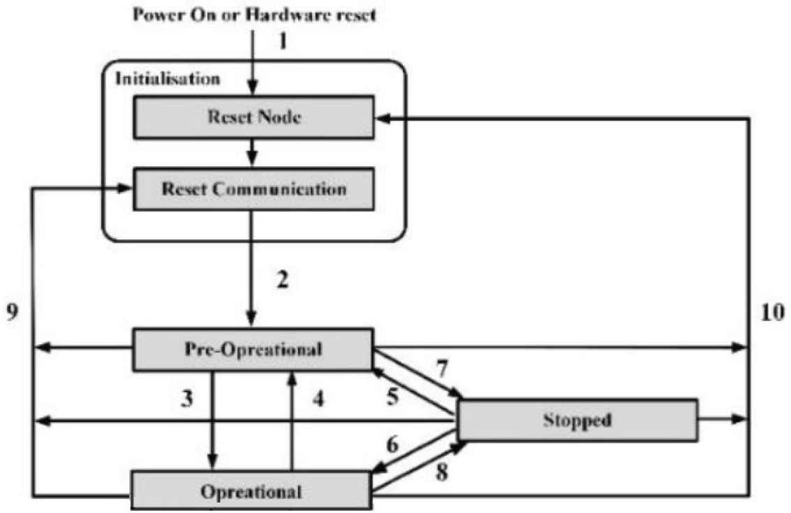
NMT state machine [4]. The numbers are represent the state transition and work flow of NMT state machine in CANopen protocol.
Communication objects may only be executed if the devices involved in the communication are in the appropriate communication states. Table 2 shows the communication objects and states.
| Initialization | Pre-operation | Operation | Stopped | |
|---|---|---|---|---|
| PDO | √ | |||
| SDO | √ | √ | ||
| SYNC | √ | √ | ||
| Time stamp | √ | √ | ||
| EMCY | √ | √ | ||
| Boot-up | √ | |||
| NMT | √ | √ | √ |
States and communication objects [4]
2.2.2. Service data objects
According to data transfer direction is divided into upload and download methods. Data frame of SDO consists of COB-ID, length and 2–8 Bytes data. Within 8 Bytes, Byte 0 is Command Specifier (CS) which is data length of the object, Bytes 1 and 2 are index of the object within OD, Byte 3 is sub-index of the object, and Bytes 4–7 are parameter of the object. SDO frame is shown in Figure 3.
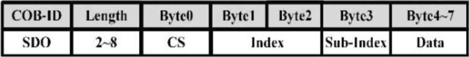
CANopen SDO frame.
2.2.3. Process data objects
Process data objects transmission priority is higher than SDO, so PDO is often used to transfer data in real time. PDO divided into Transmit PDO (TPDO) and Receive PDO (RPDO). TPDO is transmitted from the node to the master. In contrast, RPDO is the node to receive messages from the master. Before using PDO, set PDO Communication Parameter and PDO Mapping Parameter through SDO to complete mapping.
2.3. Device and Motion Control of CANopen
Controller area network in automatic released CiA402 protocol, and it is the standardized CANopen device profile for digital controlled motion products. Establishing device states machine for manage device. The state machine describes the device status and the possible control sequence of the drive shown in Figure 4. Within OD, Controlword (index: 6040h) could switch device status. Statusword (index: 6041h) could store device current status.
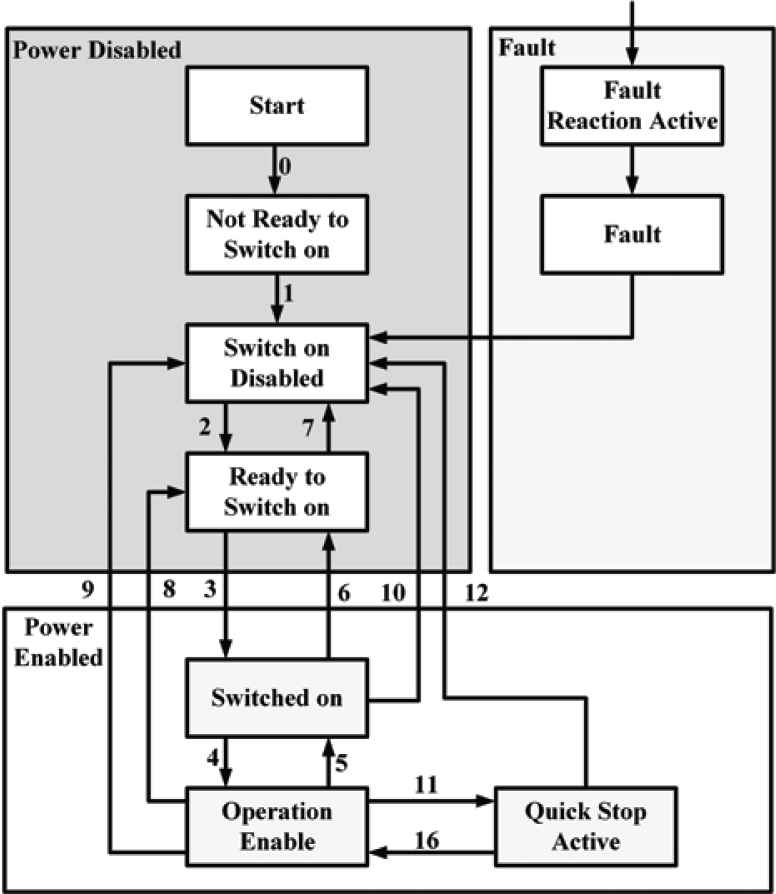
Device state machine [5]. The numbers are represent the state transition and control sequence of the device state machine in CiA402 protocol.
3. SYSTEM DEVELOPMENT AND DESIGN
3.1. System Networking Structure
The designed CANopen network structure is shown in Figure 5. The main network has one monitoring mode and two tool machine (six motor nodes). The main function of monitoring node is to monitor the whole CANopen network states. All equipment nodes possess CANopen protocol to establish the whole set of CANopen network system.
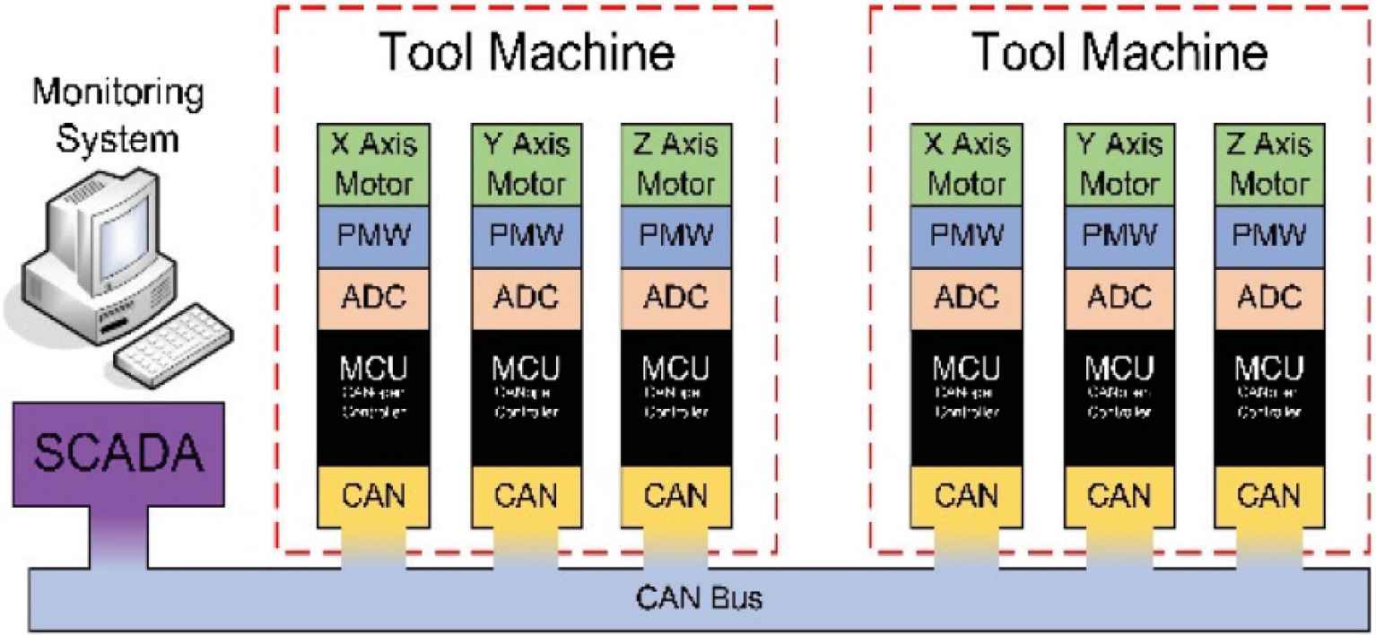
Architecture of network system.
3.2. CANopen Controller Design
The controller firmware is designed to meet the specifications of CANopen standard agreement. CANopen communication applications are mainly based on CiA301 specification which describes NMT, SDO and PDO. This proposed controller needs to implement with the motor motion control specification subjected to the CiA402 protocol. It is also additionally equipped with a motor-specific incremental encoder to receive the motor feedback signal, so as to realize the motor speed control and high-precision positioning control [6].
3.3. PDO Mapping Schedules
In order to implement the real-time monitoring of the production line on Supervisory Control and Data Acquisition (SCADA) system, the PDO mapping is planned for each axis controller of machine devices. The PDO mapping scheduling table is shown in Table 3. Since each axial operation of tool machine is controlled by the corresponding motor, all the mapping and communication parameters of CANopen TPDO and RPDO are set in accordance with the CiA402 profiles. The Controlword (6040h) and Mode of Operation (6060h) of RPDO mapping can set for the device status and device operating mode at the same time, while Target Position (607Ah) and Profile Velocity (6081h) can simultaneously deliver the commands of target position and motor speed. In addition, TPDO is used to receive the current equipment status, operating mode, actual motor position and digital inputs on SCADA system.
| PDO name | Mapped object #1 | Mapped object #2 | Index | Data length |
|---|---|---|---|---|
| RPDO1 | Controlword | Mode of operation | 6040h, 6060h | 3 Bytes |
| RPDO2 | Target position | Profile velocity | 607Ah, 6081h | 8 Bytes |
| TPDO1 | Statusword | Modes of operation display | 6041h, 6061h | 3 Bytes |
| TPDO2 | Position actual value | 6064h | 4 Bytes | |
| TPDO3 | Digital inputs | 60FDh | 4 Bytes | |
| TPDO4 | RFID UID | C000h | 4 Bytes |
PDO mapping scheduling table
3.4. Monitoring System Design
The SCADA system is the main monitoring of the Bus, which monitors the entire CANopen and the network status of each node, and displays the real-time CAN data below the SCADA system interface. Its function can be divided into four tabs, Initialize, NMT, Line. The interface of SCADA system is shown in Figure 6.
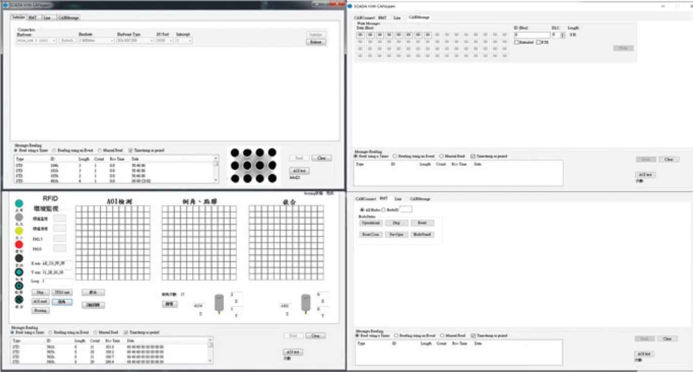
Monitoring interface: SCADA system.
4. SYSTEM INTEGRATION AND APPLICATION
4.1. Application Field of Production Line
In this study, the heterogeneous infixed chopsticks are selected as the product of production line. The infixed chopsticks are mainly made of stainless steel in the front section, and plastic or acrylic in the rear section, as shown in Figure 7. The production process of infixed chopsticks is mainly completed by three major steps: (1) chamfering: reaming, (2) gluing: fixing, and (3) infixing: molding.
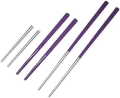
Infixed chopsticks and parts.
4.2. Design and Construction of Production Line
The production line system consists of the incoming inspection platform, two machine tools and a set of handling robot. The system architecture of the production line is depicted in Figure 8. The controllers of the two tool machines are operated in accordance with the CiA protocol. The handling robot is controlled by I/O ports on host controller.
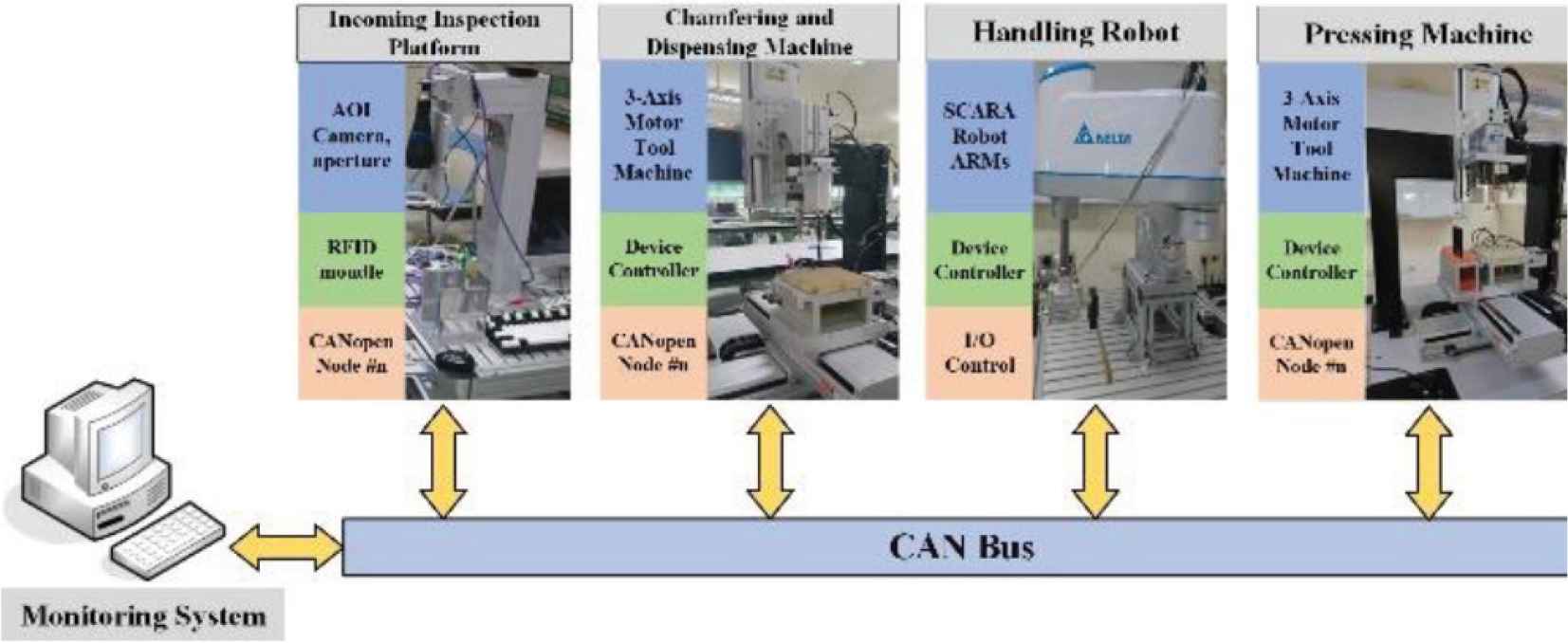
System architecture of production line.
The field planning of infixed chopsticks production line is shown in Figure 9. It presents that each machine of the working platform is quite close, and the location of each machine is mainly determined by the arm working range of Selective Compliance Assembly Robot Arm (SCARA) handling robot. The production line layout is planned according to the environmental space.
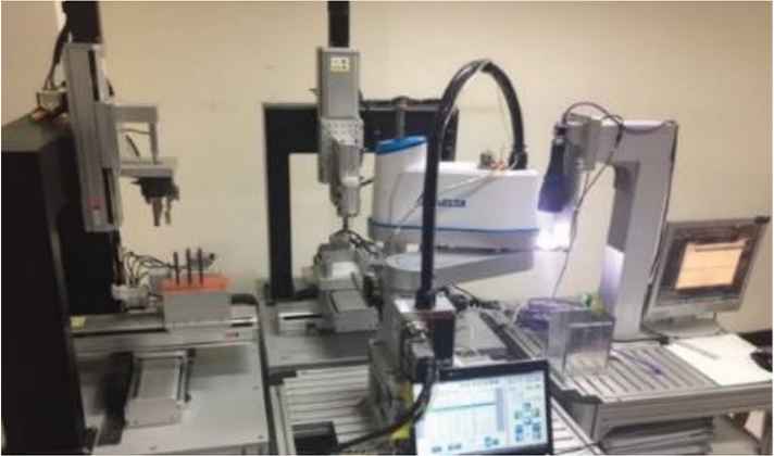
Application field of production line.
4.3. SCADA Monitoring System
The SCADA system of production line is mainly used to display the real-time situation and screen on the monitoring interface, as shown in Figure 10. In order to clearly indicate the conditions of each hole on the fixture, 144 holes on the fixture are simulated and displayed. Different icons are illustrated according to the current processing status of the infixed chopsticks at the workstation. The programming Graphical User Interface (GUI) is designed with function buttons of various situations to give commands to each workstation.
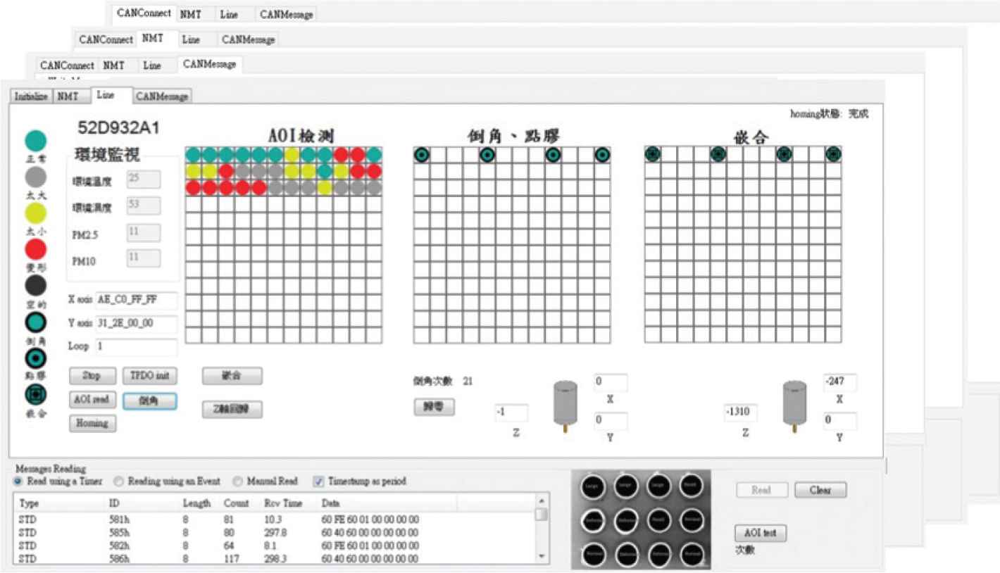
GUI interface of SCADA system.
4.4. Incoming Inspection Platform
The incoming inspection platform is the starting station of production line and responsible for managing whether the fixture enters the station and detecting whether the incoming is suitable for processing. The incoming inspection platform includes an Radio Frequency IDentification (RFID) sensing module and an automated optical inspection system. The RFID sensing module is used to determine whether the fixture has entered the station, as shown in Figure 11. The automatic optical inspection system is introduced to inspect the processing materials, eliminate the bad incoming materials, and reduce the wear of the drilling cutter, as shown in Figure 12.
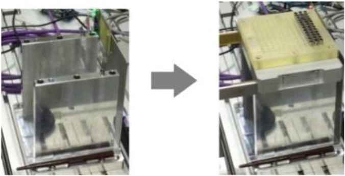
RFID sensing module and operations.
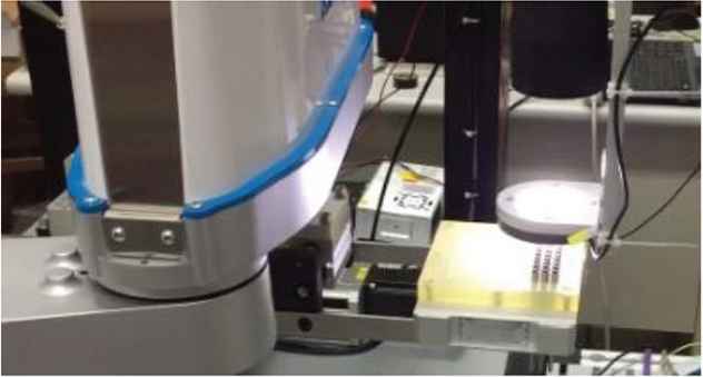
Automated optical inspection system.
4.5. Chamfering and Gluing Machine
The chamfering and gluing machine is a kind of flexible manufacturing equipment with the chamfering and gluing functions in the production processes of infixed chopsticks. First, the machine completes the setting of Controlword and Mode of Operation via RPDO1 to switch the device status and operation mode. The real-time status of the machine can be viewed and checked through TPDO1. Next, the machine is switched to Homing Mode operation mode to set the homing speed, homing acceleration and homing method, as shown in Table 4. The machine tool must complete the homing action to ensure that the starting position of each axis is correct.
| Index | Object | Name | Type |
|---|---|---|---|
| 607Ch | VAR | Home offset | INTEGER32 |
| 6098h | VAR | Homing method | INTEGER8 |
| 6099h | ARRAY | Homing speeds | UNSIGNED32 |
| 609Ah | VAR | Homing acceleration | UNSIGNED32 |
Related objects of Homing Mode
Then Profile Position Mode is selected to rotate the machine to the specified position according to the setting speed of user. SDO is used to set the acceleration and deceleration, while RPDO2 is used to set the target speed and target position, as shown in Table 5. TPDO1 and TPDO2 is used to confirm whether the machine has been turned to the set target position. Through RPDO2, new target positions can be set continuously to move the three rotation axes of the chamfering and gluing machine, and cooperate with the action of the pneumatic valve to complete the chamfering or gluing process, as shown in Figures 13 and 14.
| Index | Object | Name | Type |
|---|---|---|---|
| 6064h | VAR | Position actual value | INTEGER32 |
| 607Ah | VAR | Target position | INTEGER32 |
| 6081h | VAR | Profile velocity | UNSIGNED32 |
| 6083h | VAR | Profile acceleration | UNSIGNED32 |
| 6084h | VAR | Profile deceleration | UNSIGNED32 |
Related objects of Profile Position Mode
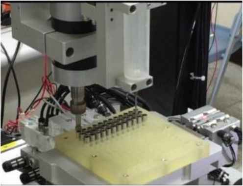
Chamfering process.

Gluing process.
4.6. Infixing and Molding Machine
The infixing machine implements the infixing process of infixed chopsticks. Same as the chamfering machine, SDO and RPDO1 are used to complete the homing position return. Then the machine is switched to Profile Position Mode. The SDO, RPDO1 and RPDO2 are used to set continuously the movement target position, so that the motor of each axes is rotated to the correct position to achieve the infixing and molding process shown in Figure 15.

Infixing and molding process.
5. CONCLUSION
In this paper, the CANopen node controller and the integration of intelligent production line is studied and developed by applying the CANopen protocol. The CAN bus is used to serve as the communication backbone by using CANopen as the high application-layer protocol. Moreover, the SCADA system communicates with each node through CAN Bus to complete the task of constructing and managing the entire network. Further, the control commands are released and the effective data transmission and reception processing is performed on all the nodes, so that the operator can immediately monitor the condition of the production line. In summary, the functional testing of application field is performed to evaluate the system performance of the entire system network monitoring and management.
CONFLICTS OF INTEREST
The authors declare they have no conflicts of interest.
ACKNOWLEDGMENTS
This research was supported by the Ministry of Science and Technology, Taiwan, R.O.C. under Grant: MOST 107-2218-E-150-001 and 107-2218-E-150-007.
AUTHORS INTRODUCTION
Prof. Chau-Chung Song
 He received the M.S. degree in Control Engineering in 1994 and the PhD degree in Electrical and Control Engineering from National Chiao Tung University in 2001 at Taiwan. He is currently a distinguished professor in Department of Aeronautical Engineering, National Formosa University. His research interests include the analysis and control of nonlinear systems the integration application of networking information system, the UAV technology, and the cloud network and Cyber-Physical system (CPS).
Mr. Yu-Wei Ho
 He received his Bachelor’s degree from the Department of Aeronautical Engineering, National Formosa University, Taiwan in 2017. He is currently a Master course student in National Formosa University, Taiwan.
Dr. Yu-Kai Chen
 He received the PhD degree in Electrical Engineering from National Chung Cheng University, Chiayi, in 1999. In 2015 and 2019, he received the outstanding industry collaboration awards from National Formosa University. His research interests include modeling and control of power converters, design of solar panel-supplied inverters for grid connection, and MCU-based application systems with fuzzy and robust controls.
Dr. Chung-Wen Hung
 He received the PhD degree in Electrical Engineering from National Taiwan University in 2006. Currently, he is an associate professor in National Yunlin University of Science & Technology. His research interests include IoT, IIoT, Power Electronics, Motor Control, and AI Application.
REFERENCES
Cite this article
TY  - JOUR
AU  - Chau-Chung Song
AU  - Yu-Wei Ho
AU  - Yu-Kai Chen
AU  - Chung-Wen Hung
PY  - 2020
DA  - 2020/05/14
TI  - Design and Application of Intelligent Networking Integration System with CANopen Protocol for Tool Machine Production Line
JO  - Journal of Robotics, Networking and Artificial Life
SP  - 1
EP  - 6
VL  - 7
IS  - 1
SN  - 2352-6386
UR  - https://doi.org/10.2991/jrnal.k.200512.001
DO  - 10.2991/jrnal.k.200512.001
ID  - Song2020
ER  -