
Par4 Parallel Robot Trajectory Tracking Control Based on DMR-GWO2 and Fuzzy Predictive
 , Zhengfeng Ming2
- DOI
- 10.2991/ijcis.d.210514.001How to use a DOI?
- Keywords
- Parallel robot; Trajectory tracking control; Type-2 fuzzy predictive compensation controller; Grey wolf optimizer
- Abstract
A dynamic Grey Wolf Optimizer (GWO) is proposed, noted as DGWO2, and a novel dynamic improved GWO algorithm is obtained after transferring the mutation operator and the eliminating–reconstructing mechanism to the DGWO2, noted as DMR-GWO2. A Type-2 fuzzy predictive compensation PID trajectory tracking controller based on the DMR-GWO2 is proposed to attain the tracking targets for the trajectory control of Par4 parallel robot. In the trajectory tracking controller, the DMR-GWO2 is designed for optimizing the Type-2 fuzzy logic controller which is in parallel with the PID controller to speed up the response of the parallel robot and to get the high adaptive capacity of the whole system. One input of the Type-2 fuzzy logic controller is the tracking error, while the other input is the sum of the derivative of the tracking error and the change rate of the expected angle. Finally, the experiments verify the effectiveness of the designed trajectory tracking controller and the tracking errors are small.
- Copyright
- © 2021 The Authors. Published by Atlantis Press B.V.
- Open Access
- This is an open access article distributed under the CC BY-NC 4.0 license (http://creativecommons.org/licenses/by-nc/4.0/).
1. INTRODUCTION
Robot, as a powerful substitute for human labor, is serving many industries. The control of robot will directly affect its performance [1,2]. The control of the robot is generally divided into two steps, namely the path planning and the trajectory tracking control. The path planning includes the path shape planning and the motion planning [3]. And the trajectory tracking control [4] is to make the robot run on the planned trajectory by designing the trajectory tracking controller, which is an important aspect of the robot control and is also a hot topic in the robot research. At present, there are already a lot of researches on the robot trajectory tracking [5]. In the literature [6], a simplified dynamic model is taken as the consideration and it is verified that the control scheme designed for the trajectory tracking based on the robot reduced model could improve the trajectory tracking accuracy. In the literature [7], a five degree of freedom hybrid robot model predictive trajectory tracking controller for milling is designed, and the control law of calculating torque is planned to improve the performance of trajectory tracking. In the literature [8], a novel hybrid humanoid robot arm is the controlled object, an sliding mode controller based on the adaptive backstepping approach is introduced under considering the parameter uncertainties and disturbances, and finally the superiority of the trajectory tracking controller is verified by experiments. In the literature [9], the adaptive controller based on the output is proposed for a Delta robot, which is applied to implement the trajectory tracking and is helpful to gain the fast tracking of the reference trajectory. In the literatures [10–13], the trajectory tracking controllers have taken the advantages of easy implementation and parameter convenient adjustment with PID controller, and most of the improvements are embodied in the PID parameters, meaning that a variety of online real-time adjusting strategies of PID parameters are introduced to enhance the adaptive ability of the controller. Thus the adaptive ability of such controller is greatly influenced by the designed parameter control law, which to some extent depends on the designer's experience, being not conducive to the widespread usage.
The tracking error is an important index to measure the effect of trajectory tracking for the robot. The smaller the tracking error is, the better the control effect will be. Thus, the robot tracking control often needs to be combined with the optimal control. The key of the optimal control lies in the design of the optimization algorithm. Considering the higher requirements on the accuracy of the robot control and the strong coupling complex nonlinear of the robot system, it would be difficult to solve the optimization problem with the traditional optimization algorithm for the robot. However, the computational intelligence technology has the characteristics of the strong adaptive ability and the robustness [14,15], providing an effective way for the robot to solve such complex optimization problem. In the literature [16], a navigation method for a three-wheeled omnidirectional mobile robot (TWOMR) based on the fuzzy behavior has been proposed. In the literature [17], the autonomous bicycle robot is as the object of study. The trajectory planning and the tracking control have been carried out for it, the polynomial curve is obtained through minimizing the maximum of the desired roll angles equilibrium determined, and the PSO is taken to solve the optimization problem. In the literature [18] the combination of the neural network control and the genetic algorithm (GA) is studied for the cooperative robot. To implement the good trajectory tracking control of the robot, the GA and an improved GA are applied to optimize the structure of the neural network.
The parallel robot, as an important branch of the robot, has been favored by many scientific researches for its excellent dynamic performance. In view of the above mentioned facts, for Par4 parallel robot, a Type-2 fuzzy predictive compensation PID controller based on DMR-GWO2 is proposed to make its trajectory tracking control system simple and its system highly adaptive. The DMR-GWO2 is a novel improved dynamic Grey Wolf Optimizer (GWO) based on the mutation operator and the eliminating–reconstructing mechanism [19]. The inputs of the Type2-fuzzy logic controller have been specially designed which will be explained in a later section. The PID controller and the Type-2 fuzzy logic controller are connected in parallel, which can reduce the dependence on the Par4 parallel robot model and improve the adaptive ability of the system without the need of designing the parameter control law. To further improve system performance, the DMR-GWO2 is applied for some optimization training of Type2-fuzzy logic controller.
2. TYPE-2 FUZZY CONTROLLER
The structure of the Type-2 fuzzy logic system is shown in Figure 1 [20]. When the Type-2 fuzzy logic system theory is applied in the control field, the controller will be called as the Type-2 fuzzy logic controller correspondingly.
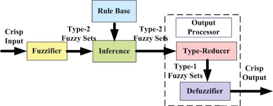
The structure of Type-2 fuzzy logic system.
3. GWO AND DMR-GWO2
3.1. Grey Wolf Optimizer
The GWO [21] mainly simulates the hierarchy and the hunting behavior of the grey wolves. The hierarchical structure is demonstrated in Figure 2, where Wolf α, β and δ are the top three leading wolves, who represents the optimal solution, the suboptimal solution and the triple optimal solution of the optimization problem respectively. Wolf ω is the lowest level grey wolf, the primary actor of the searching behavior. The hunting mechanism in the GWO could be described as (1)–(7).
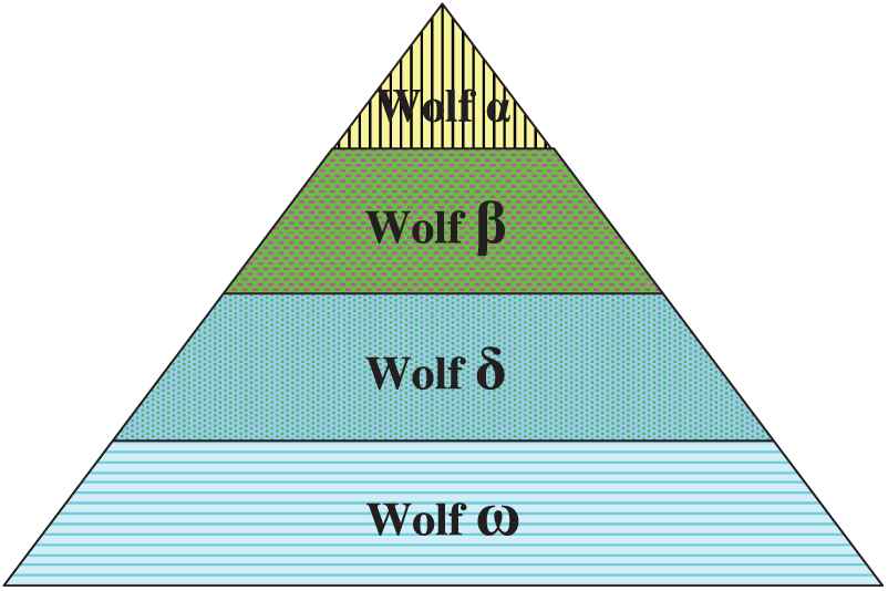
The hierarchy diagram of the grey wolf.
In (8) and (9), the elements of
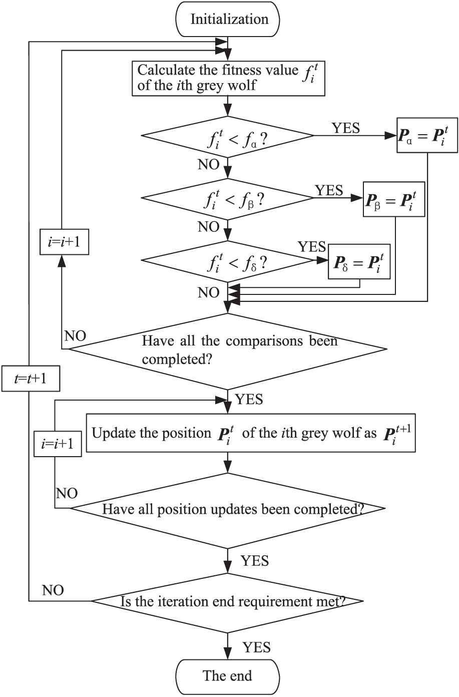
The flow chart of GWO.
In the GWO flow chart, the
From the flow chart of the GWO, it can be seen that the position update of the current grey wolf can only be carried out after completing the comparisons between all the grey wolves and the three leading wolves, which is not conducive to the fast convergence of the algorithm. That is to say, the current grey wolf updates its position needing to wait the comparisons of other wolves. For this kind of waiting, the standard GWO is known as a “static” algorithm. To speed the convergence of the GWO up, the dynamic GWO is proposed.
3.2. The Dynamic GWO
To get rid of the “waiting,” the dynamic GWO is proposed and its flow chart is shown in Figure 4. Seen from Figure 4, compared with the standard GWO, the current grey wolf can directly update its position without waiting for the comparisons between other grey wolves and the three leading wolves, thus, it is thought as the “dynamic” GWO, noted as DGWO. In Figure 4, the position update of the current grey wolf is performed before the calculation of its fitness value, and also before the comparison between the grey wolf and the three leading wolves. The sequence of procedures is different from the standard GWO, to highlight the differences, the number “2” is added to the abbreviations, DGWO, namely denoted as DGWO2.
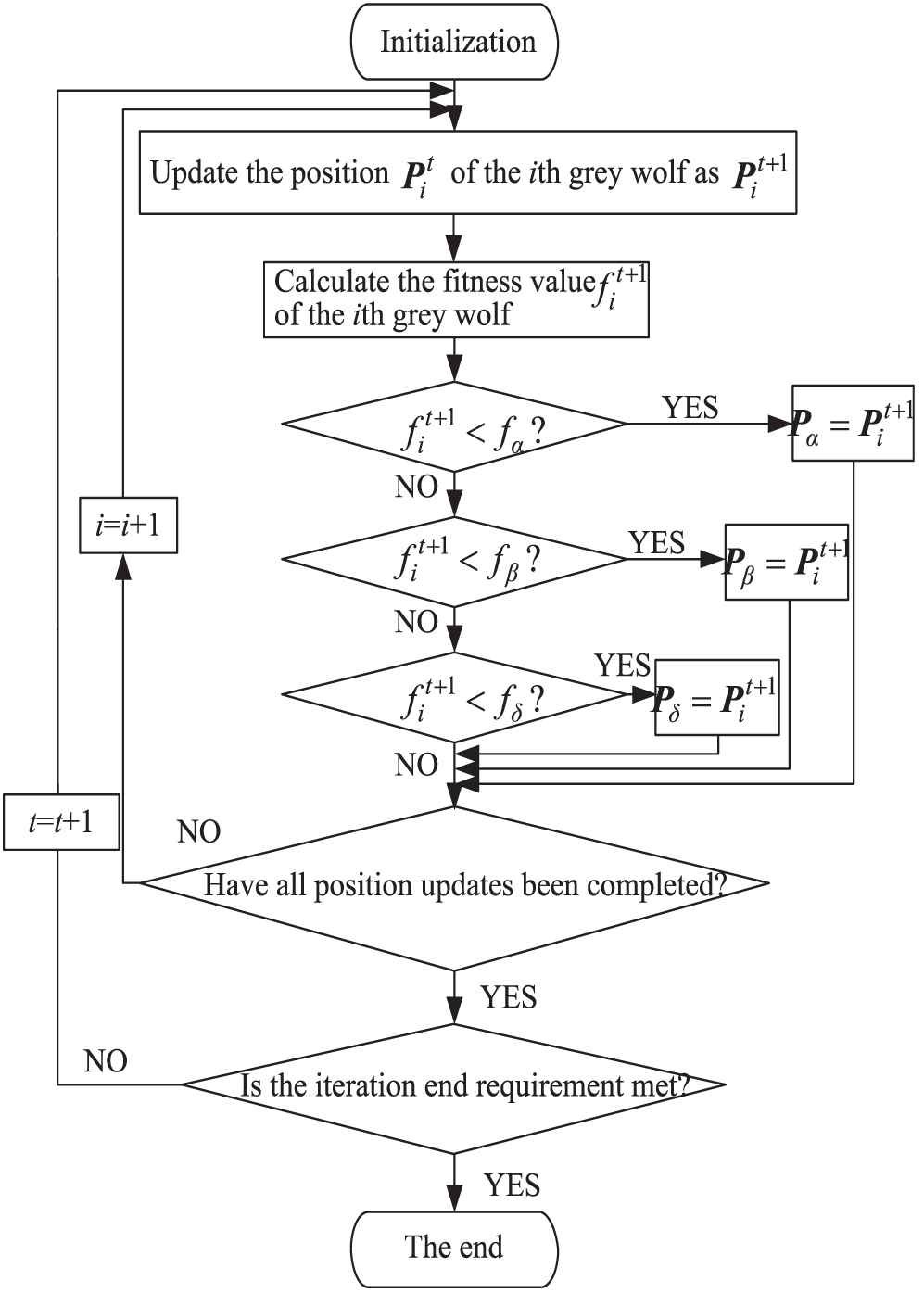
The flow chart of the dynamic GWO (DGWO2).
In the DGWO2, the embodiment of the “dynamic” is just to perform the position update in a timely manner, and the newfound
3.3. The Improved Dynamic GWO
The GWO algorithm is excellent, but it is not perfect, and many other improved GWO algorithms have been known so far. The DGWO2 retains all program statements in the GWO, but only adjusts their order of execution. Therefore, it could be considered to transfer the previous improvements based on the GWO to the DGWO2. Such improvements may have better performance. Some discussions have been made in the literature [22] where it is found that the effect of transferring the mutation operator and the eliminating–reconstructing mechanism (MR-GWO) [19] to the DGWO2 is very good. And the improved DGWO2 based on the mutation operator and the eliminating–reconstructing mechanism is noted as DMR-GWO2. The DMR-GWO2 could be described as follows:
Algorithm 1 The DMR-GWO2
Initialize the search wolves
Initialize Parameters a, A, λ, η, F and Pm
Initialize the leading wolves
Calculate the fitness of the leading wolves
While (t < Maximum number of iterations)
for each search wolf
Update the search wolf
Calculate the fitness of the updated search wolf
Update the leading wolves
end for
Sort the fitness of search wolves;
Perform the mutation operation for the excellent search wolves;
Eliminate the poor search wolves and reconstruct them;
end while
Return
The detailed comparison and experimental verification of the GWO, DGWO2 and DMR-GWO2 have been carried out with the CEC2014 test functions as the optimized objects [22]. Moreover, among many other comparison algorithms, the DMR-GWO2 is also the best, either from the statistical number of the optimal values or from the perspective of the “rank value,” that is why it is selected to optimize the tracking controller of the Par4 robot. In view of space, the experiments would not be described in detail here.
4. PAR4 TRACKING CONTROLLER
4.1. Expected Trajectory
The structure diagram of Par4 parallel robot is shown in Figure 5, which mainly includes the fixed platform, the moving platform and the branch chain consisting of the big arm and the small arm. The moving platform is the execution end of the Par4 parallel robot. The fixed platform mainly includes an installing frame and four servo motors [23].
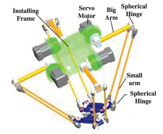
The structure diagram of Par4 parallel robot.
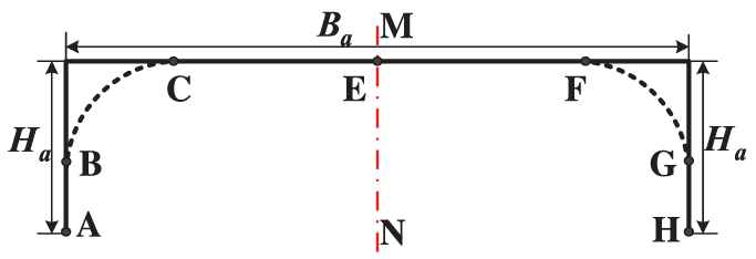
For Par4 parallel robot, the high-speed pickup is one of the main operations. The gate-shape pick-and-place trajectory is shown in Figure 6, in which the right-angle transition could be rounded with some smooth curve. The planned angle curves of the Par4 parallel robot are shown in Figure 7 [23], which are obtained by the trajectory planning and optimization with the lowest mechanical energy consumption, the lamé curve as the smooth transition curve and the asymmetric quintic polynomial as the motion law. To control the Par4 parallel robot with high precision, it is necessary to study the trajectory tracking control.
The structure diagram of Par4 parallel robot.

The planned angle trajectory of Par4 parallel robot.
4.2. The Structure of Tracking Control System
The trajectory tracking control will be studied on the joint level. Taking the joint drive motors of the Par4 parallel robot end-effector as the controlled objects, the structure of the whole trajectory tracking control system is illustrated in Figure 8.
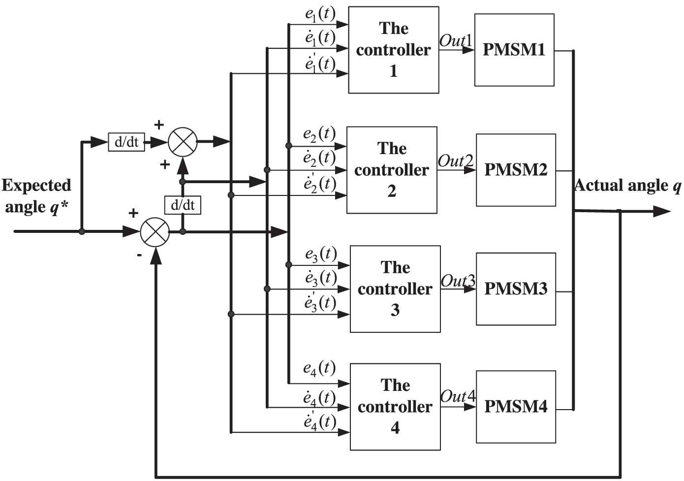
The trajectory tracking control structure of the whole system.
In Figure 8,
The expected angle vector
4.3. The Tracking Controller of Par4 Robot
The tracking controller is shown in Figure 9, where a Type-2 fuzzy predictive compensation PID controller based on the DMR-GWO2 is seen. The Type-2 fuzzy predictive compensation controller optimized by the DMR-GWO2 is parallel to the PID controller. As above, the
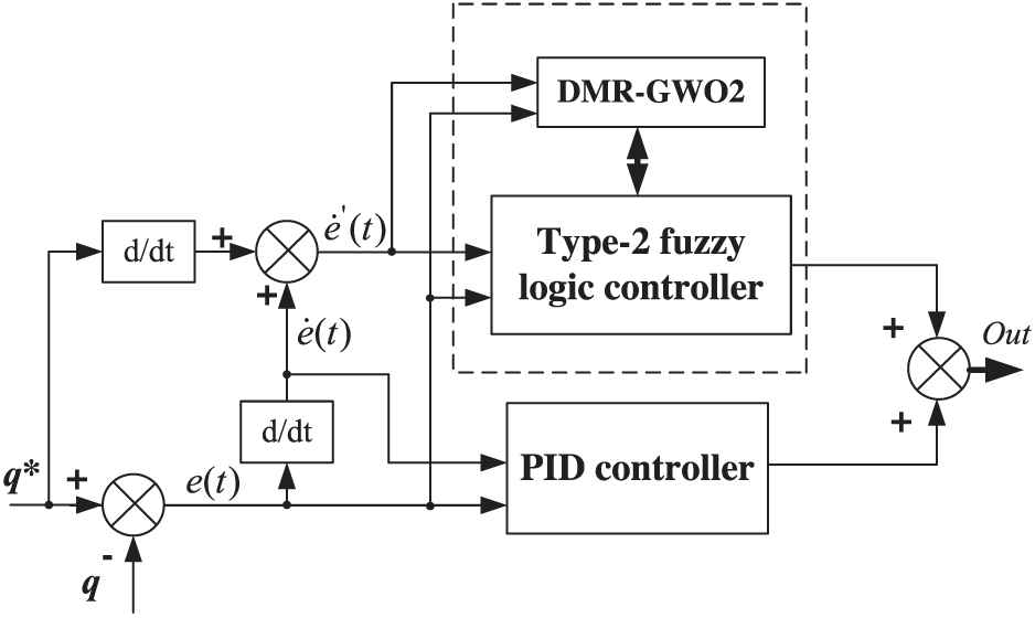
The structure of Type-2 fuzzy predictive compensation PID controller.
The initial range of the tracking error
The main membership function
The footprint of uncertainty (FOU) of Type-2 fuzzy set are shown as follows:
The initial range of the
The interval Type-2 fuzzy set is involved in the output of fuzzy inference and the normalized output scope is limited in [−1, 1], and seven fuzzy variables are designed, which represent negative big (NB), negative medium (NM), negative small (NS), zero (ZE), positive small (PS), positive median (PM) and positive big (PB), respectively. The fuzzy rules are shown in Table 1.
| NB | NM | NS | ZE | PS | PM | PB | |
|---|---|---|---|---|---|---|---|
| N | NS | NM | ZE | ZE | ZE | PS | PM |
| Z | NM | NS | ZE | ZE | ZE | PS | PM |
| P | NB | NM | NS | ZE | PS | PM | PB |
The fuzzy inference rules.
4.4. The Optimization Based on DMR-GWO2
The DMR-GWO2 is mainly applied to optimize the input range, the output weighting factor, several parameters of
In order to reduce the complexity of the optimization, only integer optimization is carried out for the input range and the output weight factor, which will also reduce the search time. After experimental verification, the optimization range of the tracking error
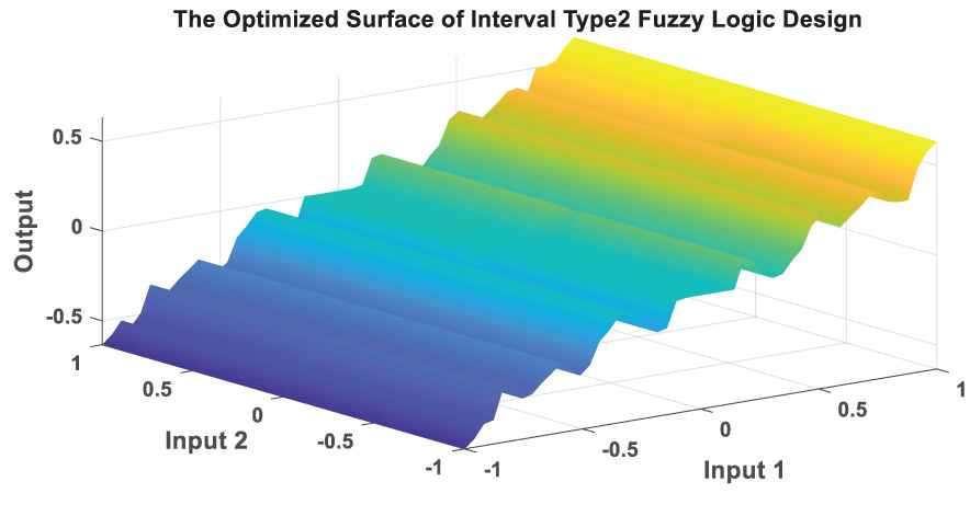
Optimized fuzzy model.
5. TRAJECTORY TRACKING EXPERIMENT
5.1. The Experiment Platform
The experimental platform of the Par4 parallel robot is shown in Figure 11. It includes the robot bracket, the fixed platform, the moving platform, the servo drives, servo motors, the terminal board, the computer with motion control card and so on.
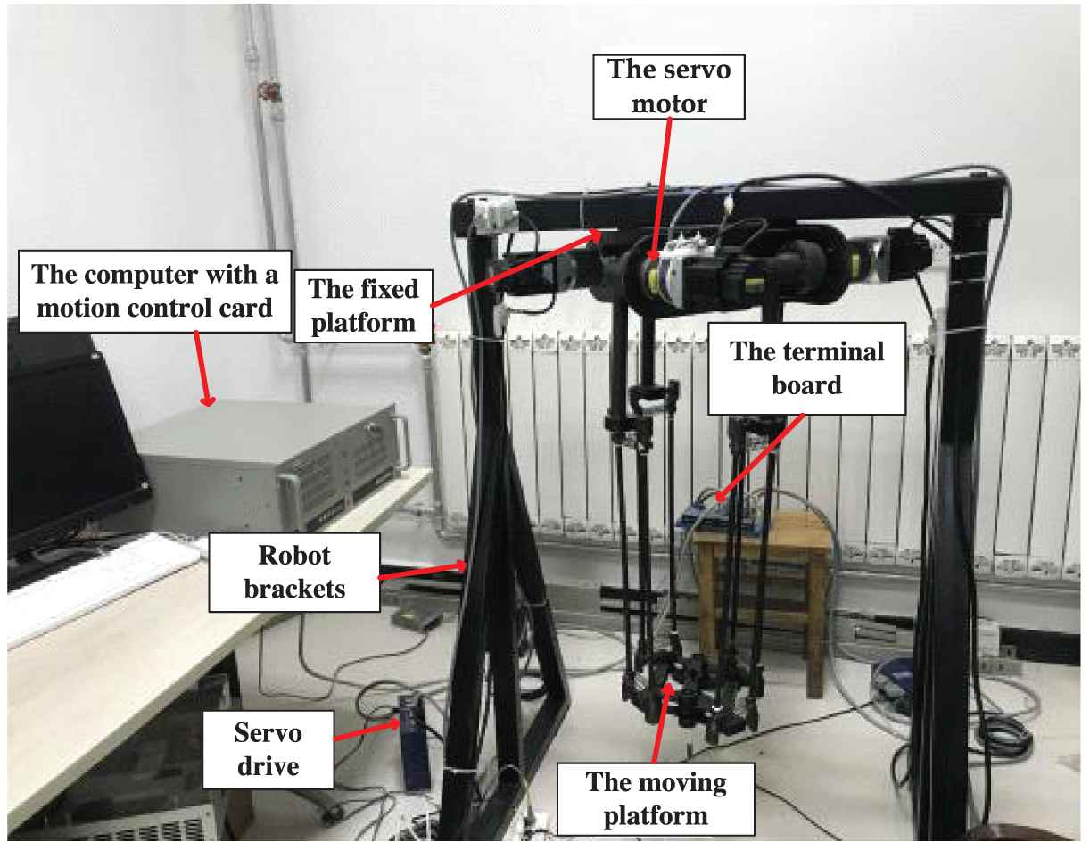
The experimental platform of Par4 parallel robot.
5.2. The Experiment Results
The angle tracking results of the Par4 parallel robot are shown in Figure 12. The coordinates of the starting and ending points of the pickup of the Par4 robot are
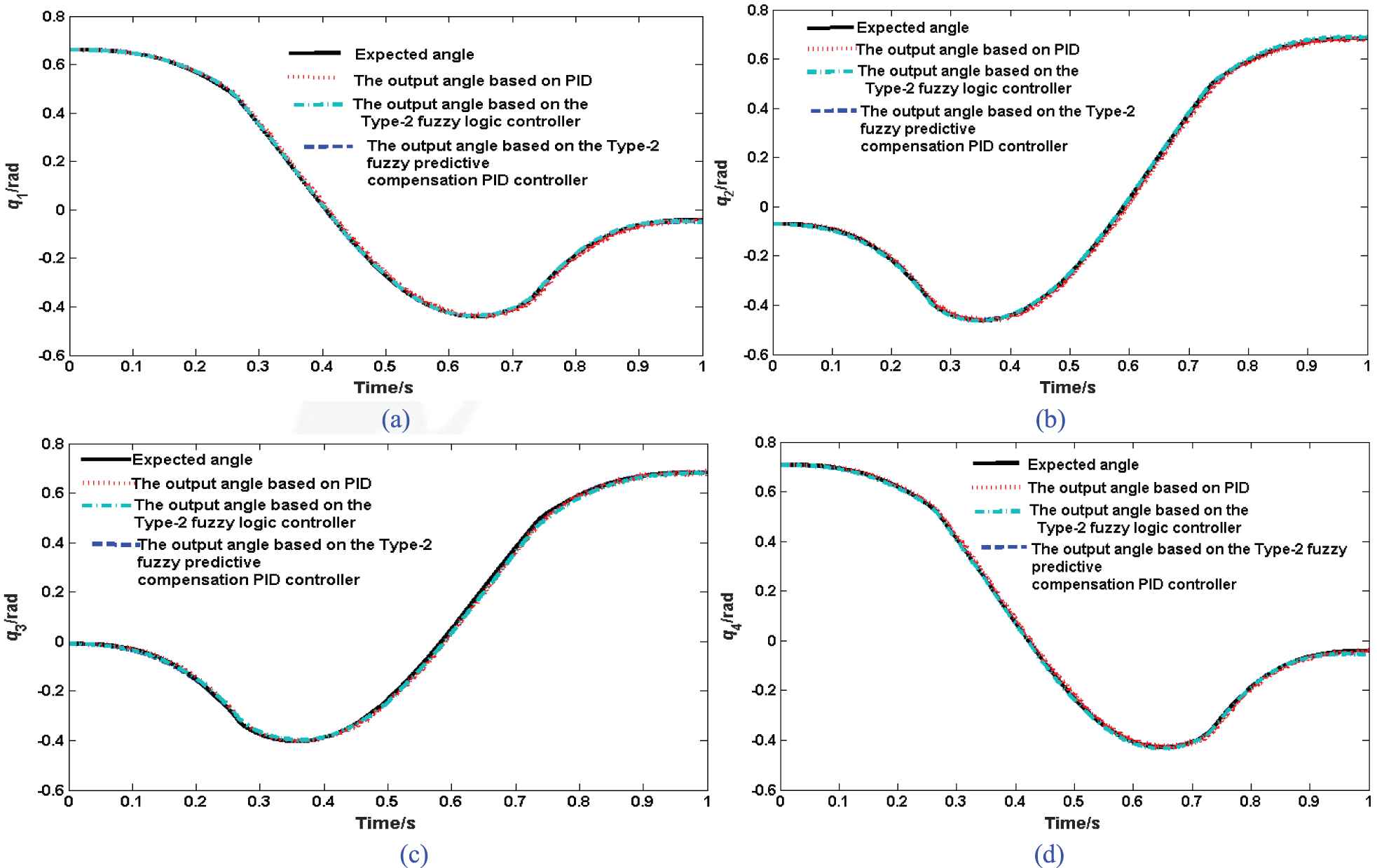
The output angle results of Par4 parallel robot. (a) is the angle results of Motor 1, (b) is the angle results of Motor 2, (c) is the angle results of Motor 3 and (d) is the angle results of Motor 4.
5.3. Discussion and Analysis
The discussion about the three controller
The angle tracking error curves are shown in Figure 13 where the angle tracking error of the controller designed in this paper is significantly smaller than that of the PID controller and that of the Type-2 fuzzy logic controller, which further illustrates the good tracking effect. The Type-2 fuzzy logic control and the PID controller in parallel connection can complement each other in function. The maximum absolute error of the Type-2 fuzzy predictive compensation PID controller is less than 0.01 rad, meaning that the error can be controlled at the thousandth level. In a word, it has clearly shown that there is good effect on the control of the angle tracking with the Type-2 fuzzy predictive compensation PID controller.
The comparative analysis of the angle errors before and after the optimization
The comparison results are obtained in Figure 14 about the angle tracking errors of the robot before and after the optimization of the Type-2 fuzzy logic controller. Before the optimization, it means that the parameters of the designed controller are the initial values, and after the optimization, it means that the parameters of the Type-2 fuzzy logic controller are the optimized values by the DMR-GWO2. It can be seen from Figure 14 that, after optimizing, the angle tracking errors are significantly decreased, and the maximum absolute error of the tracking angle can be reduced by more than 50%, which fully demonstrates the effectiveness of optimization based on the DMR-GWO2.
The discussion of input variables
According to the analysis, it is known that the difficulty of the angle tracking control for the robot lies in that the expected motor angle is not a constant value and varies with time, meaning the higher tracking speed need to satisfy the dynamic requirements. The adjusting time of the PID control is long, easily causing the hysteresis to some extent in the tracking process, and the tracking error is relatively large. When the Type-2 fuzzy logic controller is involved in parallel with the PID controller, the output of the Type-2 fuzzy logic controller is equivalent to the one with only proportional control, accelerating the response speed of the system to a certain extent. In the experiment, it is found that if the inputs of the Type-2 fuzzy logic controller only include the two variables, the angle error
The following is an experimental comparative analysis of the inputs designed above. When the angle tracking controller has the same structure and all parameters in the controller have the same values, only the two different sets of inputs of the Type-2 fuzzy predictive compensation controller are discussed. The one set of inputs are thought as the conventional ones, meaning that the inputs of the Type-2 fuzzy predictive compensation controller are the angle tracking error
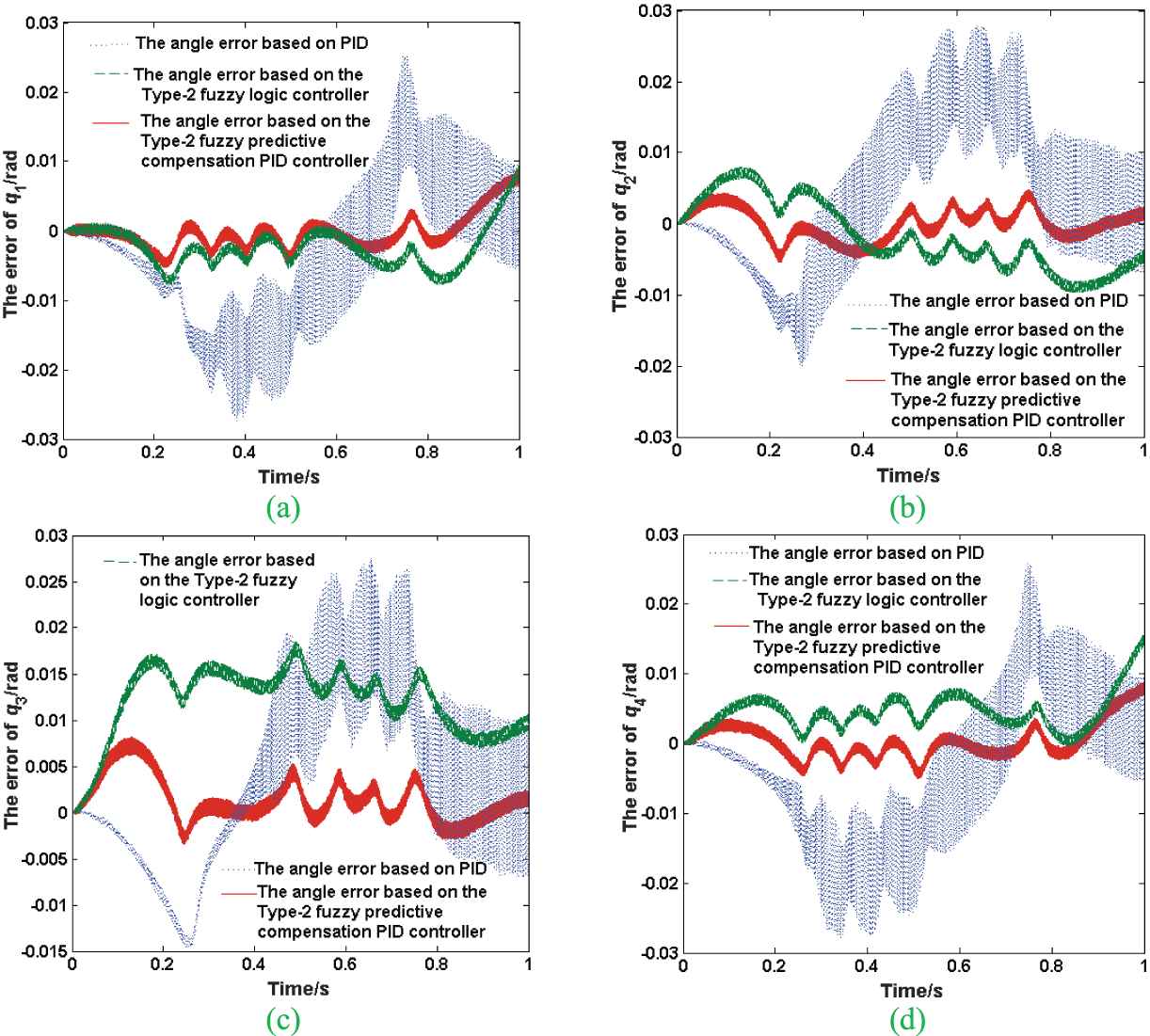
The angle errors of Par4 parallel robot. (a) is the angle errors of Motor 1, (b) is the angle errors of Motor 2, (c) is the angle errors of Motor 3 and (d) is the angle errors of Motor 4.
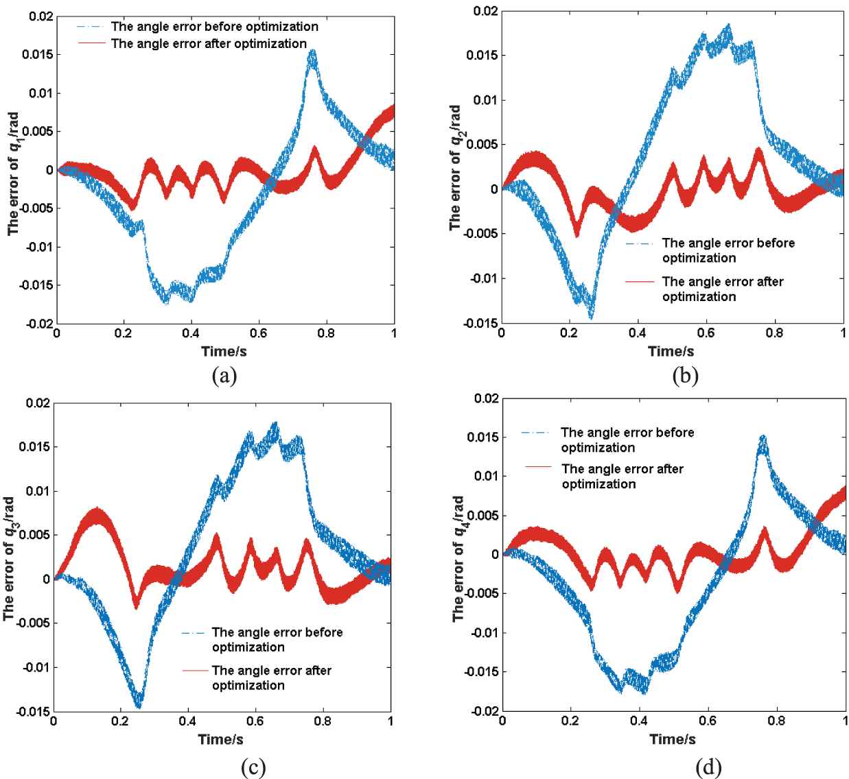
The comparison results of the angle errors before and after the optimization. (a) is the angle errors of Motor 1, (b) is the angle errors of Motor 2, (c) is the angle errors of Motor 3, and (d) is the angle errors of Motor 4.
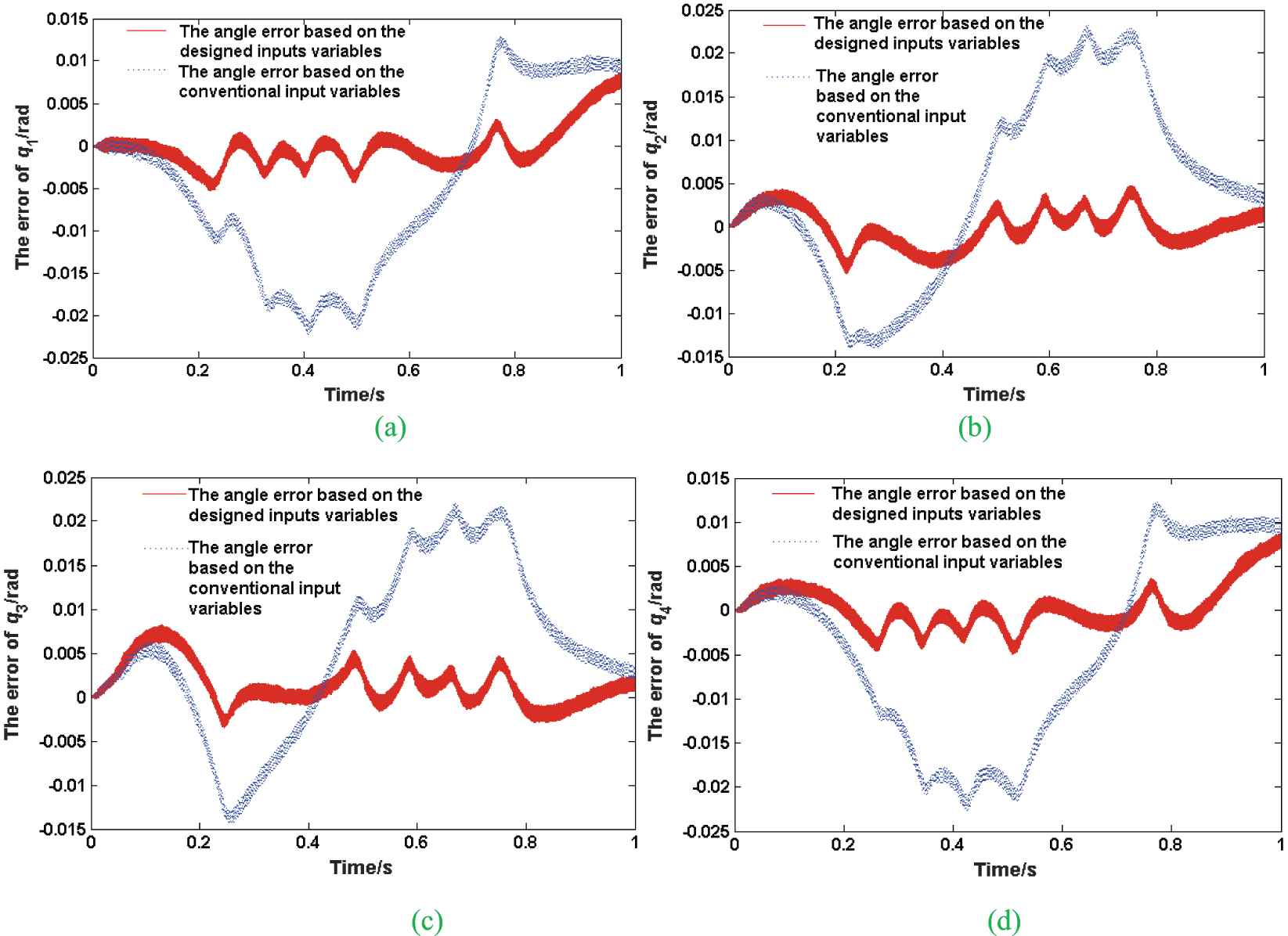
The comparison results of the angle errors with different inputs. (a) is the angle errors of Motor 1, (b) is the angle errors of Motor 2, (c) is the angle errors of Motor 3 and (d) is the angle errors of Motor 4.
6. CONCLUSION
A Type-2 fuzzy predictive compensation PID controller based on the DMR-GWO2 is proposed to track the planned trajectory for the Par4 parallel robot to carry out the gate-shaped pick-and-place operation. The Type-2 fuzzy predictive compensation controller is paralleled with the PID controller to speed up the response of the system, and the DMR-GWO2 is applied for the optimization of the Type-2 fuzzy logic controller. Finally, the correctness of the design is verified by experiments, and the tracking errors are all small. The selection about the change rate of the input angle being considered for one of the inputs of Type-2 fuzzy predictive compensation controller, greatly improves the system dynamic tracking effect, the tracking error of the system being reduced and the adaptive capacity of the controller being increased. The proposed intelligent PID trajectory tracking controller can effectively control the Par4 parallel robot, which lays a solid foundation for its subsequent industrial application.
CONFLICTS OF INTEREST
The authors declare no conflicts of interest.
AUTHORS' CONTRIBUTIONS
Methodology, Zhengfeng Ming; experimental verification, Xiaoqing Zhang; writing—original draft preparation, Xiaoqing Zhang; writing—review and editing, Xiaoqing Zhang; supervision, Zhengfeng Ming; project administration, Zhengfeng Ming.
Funding Statement
This research was funded by the Scientific Research Plan Projects (No. 20JK0972) of Shannxi Education Department and the National High Technology Research and Development Program (863) (No. 2015AA7041003) of China.
REFERENCES
Cite this article
TY  - JOUR
AU  - Xiaoqing Zhang
AU  - Zhengfeng Ming
PY  - 2021
DA  - 2021/05/19
TI  - Par4 Parallel Robot Trajectory Tracking Control Based on DMR-GWO2 and Fuzzy Predictive
JO  - International Journal of Computational Intelligence Systems
SP  - 1597
EP  - 1606
VL  - 14
IS  - 1
SN  - 1875-6883
UR  - https://doi.org/10.2991/ijcis.d.210514.001
DO  - 10.2991/ijcis.d.210514.001
ID  - Zhang2021
ER  -