
Artificial Neural Network Based Droop-Control Technique for Accurate Power Sharing in an Islanded Microgrid
- DOI
- 10.1080/18756891.2016.1237183How to use a DOI?
- Keywords
- Artificial neural network (ANN); Microgrid; Photovoltaic (PV); Battery energy storage system (BESS); Solid oxide fuel cell (SOFC); Droop control
- Abstract
In an islanded microgrid, while considering the complex nature of line impedance, the generalized droop control fails to share the actual real/reactive power between the distributed generation (DG) units. To overcome this power sharing issue, in this paper a new approach based on feed forward neural network (FFNN) is proposed. Also, the proposed FFNN based droop control method simultaneously controls the microgrid voltage and frequency within the limits. The proposed microgrid consists of combination of photovoltaic (PV) system and battery energy storage system (BESS) as the first DG unit and solid oxide fuel cell (SOFC) as the second DG unit. The simulation of the proposed microgrid is carried out in Matlab/Simulink environment and necessary results are compared to show the effectiveness of the proposed method.
- Copyright
- © 2016. the authors. Co-published by Atlantis Press and Taylor & Francis
- Open Access
- This is an open access article under the CC BY-NC license (http://creativecommons.org/licences/by-nc/4.0/).
1. Introduction
Since the beginning of 20th century, fossil fuels such as coal, oil and natural gas has been the main source of energy to meet out the ever increasing energy demand. As a result of extensive fossil fuel consumption, millions of tons of pollutant gases (particularly CO2 gas) are released in to the atmosphere and it is considered to be the main cause of global warming1. Due to the exhausting nature of the fossil fuels and ever increasing power demand, production of electrical energy from renewable energy sources (RESs) has attracted growing research interest during the past few decades. Furthermore, the environment could be protected from further worsening if the RESs are used more intensively for energy production.
Distributed generation (DG) technology plays a significant role to overcome the aforesaid problem. DG units can be powered by both conventional power sources (fuel cells, diesel generators etc.) and RESs (solar, wind turbine, small hydro etc.)2. DG systems are decentralized and use more flexible and modular technologies to meet out the energy demand and to provide various ancillary services3. DG systems are beneficial to consumers as well as to the utilities. DG units are interfaced with the utility grid through power electronic converters4. The connection of small DG units to a low/medium voltage network potentially increases the reliability to the end users and utilities. In this context, a microgrid can be defined as a low/medium voltage network consisting of various DG’s, energy storage systems (ESS) and loads that are normally connected to the utility grid through point of common coupling (PCC). If any fault occurs on the utility grid, microgrid disconnects from the utility grid and operates in islanded (autonomous) mode and continues to supply the critical loads5.
With the presence of various conventional/RES-based DG units, the power control complexity of a microgrid system is increased significantly. Also, to ensure the “plug and play” feature of the DG units, proper control strategies have to be used. The “plug and play” feature can be realized using communication/noncommunication based control techniques. Among them, a popular non-communication based technique is the frequency and voltage droop control6. In Refs. 7–12, the line impedance of microgrid system is either considered as resistive or inductive in nature and accordingly the droop control technique is modified. In a medium voltage microgrid, the lines are considered to be inductive in nature and hence there exists a strong linkage between active power & frequency (P-f) and reactive power & voltage (Q-V). Therefore P-f and Q-V droop relations and its variants (improved droop methods) are used to control the microgrid frequency and voltage7, 8. In a low voltage microgrid, the lines are considered to be resistive in nature and hence there exists a strong linkage between active power & voltage (P-V) and reactive power & frequency (Q-f). Therefore P-V and Q-f droop relations and its variants are used to control the microgrid voltage and frequency2, 11. However in general case, the effect of both the resistance and the inductance has to be considered13, 14.
In Ref. 13, generalized droop control technique by considering the effect of complex line impedance is proposed. This technique performs well when the microgrid is operating in grid connected mode. But, it fails to share the actual real and reactive power when the microgrid is operating in islanded mode. It is because the generalized droop control is highly dependent on the output impedance of inverter and line impedances between DG units and load14, 15. In Refs. 8–10, to resolve the power sharing issues, certain modifications in droop control technique is made by adding virtual output impedance loop, derivative term or an integral term in the droop relation. However, in these literatures the complex nature of line impedance is not considered. Another drawback in generalized droop control is, when the number of DG units increases in a microgrid, it becomes tedious to calculate the value of exact line impedance between the DG units and the load. To remove its dependency on line parameters, several intelligent techniques are used in literatures15, 16.
In this paper, to address the real and reactive power sharing issues for a generalized droop control and to regulate the islanded microgrid voltage and frequency, a new intelligent approach based on artificial neural network (ANN) is proposed. The proposed ANN is realized using a feed forward neural network (FFNN) trained by levenberg-marquardt (LM) algorithm. The training data sets are collected from a simple microgrid system consisting only one DG unit under different loading conditions. These data sets are used to train the FFNN. To test and validate the performance of the proposed method, the trained FFNN is applied to the islanded microgrid consisting of two DG units. In this work, instead of using ideal sources as DG units, the actual models are developed to realize the DG units. The first DG unit comprises a parallel combination of photovoltaic (PV) power generation system and a battery energy storage system (BESS). Solid oxide fuel cell (SOFC) system is used as the second DG unit. The proposed ANN based droop control technique performs well in controlling the microgrid voltage and frequency under all conditions (during load change as well as during varying irradiance). Also, it performs well by sharing the actual real and reactive power demanded by the load. The whole system is simulated using Matlab/Simulink and the necessary results are presented to show the effectiveness of the proposed FFNN based droop control technique.
The rest of the paper is organized as follows. Section 2 describes the configuration and modeling of the proposed microgrid system. Section 3 describes about the control of parallel connected VSC’s. Section 4 describes about the generalized droop control method and its drawbacks. In Section 5, proposed ANN based droop control method is explained. In Section 6, simulation results are provided to validate the effectiveness of the proposed method. Finally in Section 7, conclusion is provided.
2. Microgrid Configuration and Modeling
Fig. 1 shows the configuration of the proposed microgrid system operating in islanded mode. It consists of two DG units. DG1 comprises a parallel combination of PV system and a BESS. DG2 comprises a SOFC system. The PV system is connected to the dc side of voltage source converter 1 (VSC1) through a dc-dc boost converter. The PV boost converter is used to extract the maximum available power from the PV array with the help of maximum power point tracking (MPPT) algorithm. Battery is connected to the dc side of VSC1 through a bidirectional dc-dc converter. The bidirectional converter facilitates proper charging and discharging control of the battery. Another important function of the BESS is to keep the dc-link voltage of VSC1 constant with the help of bidirectional dc-dc converter, irrespective of changes in PV output power. Similarly, SOFC is connected to the dc side of VSC2 through a dc-dc boost converter. VSC1 and VSC2 are connected to the PCC through an LC filter and a coupling inductor as shown in Fig. 1. Various loads are connected at the PCC. As the microgrid is operating in islanded mode, it is not connected to the utility grid.
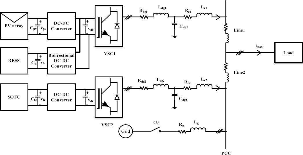
Configuration of the proposed microgrid system
2.1. Modeling and control of PV system
PV power generation system has various advantages such as no incurring fuel cost, pollution free power generation with less maintenance cost. Thus even though the PV system is posed to high fabrication cost and low conversion efficiency, it is a good alternative when compared to rapidly decreasing reserves of fossil fuels. In this work, a single diode model of a solar cell is considered to design the PV system. The modeling equations are given in Ref. 17 and it is used here to model a 4.5kW PV system. The parameters required to model the PV system are given in Ref. 18. The control diagram for the PV system is shown in Fig. 2. The input and output equations required to design boost converter are given in Ref. 19 and 20. To extract maximum power from the PV array, perturb and observe (P&O) MPPT algorithm is implemented here. The algorithm generates a reference voltage (Vpv_ref) and it is compared with the actual PV voltage (Vpv). The error signal thus generated is given to the voltage and current controllers to generate gating signals. The voltage and current controllers are realized using proportional-integral (PI) controller. The controllers gain and the component parameters are given in Table 1.
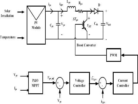
Control diagram for PV system
| System parameters | Values |
|---|---|
| Nominal ac voltage | 380 V(L-L) |
| Frequency | 50 Hz |
| DC-link voltage | Vdcref = 700 V |
| Nominal battery voltage | Vb = 500V |
| Battery capacity | 250 Ah |
| DC-link capacitor | Cdc = 7500 μF |
| DG1/VSC1 | DC-DC converter parameters |
| Cpv =100 μF, Lpv = 5 mH, | |
| Rpv = 0.005 Ω | |
| Cb = 250 μF, Lb = 0.35 mH | |
| PV voltage controller: | |
| Kp = 0.01, Ki =50 | |
| PV current controller: | |
| Kp = 0.125, Ki = 100 | |
| BESS voltage controller: | |
| Kp = 0.01, Ki = 50 | |
| BESS current controller: | |
| Kp = 0.9, Ki = 65 | |
| Rdg1 = 0.2 Ω, Ldg1 = 3 mH, | |
| Cdg1 = 15 μF, | |
| Rc1 = 0.02 Ω, Lc1 = 0.3 mH | |
| Kpv1 = 0.2, Kiv1 = 280 | |
| Kpi1 = 20, Kii1 = 1500 | |
| DG2/VSC2 | DC-DC converter parameters |
| Cfc = 1000 μF, Lfc = 0.5 mH | |
| Voltage controller: | |
| Kp = 0.01, Ki =50 | |
| Current controller: | |
| Kp = 0.05, Ki =100 | |
| Droop Gains for single | kpf = 0.003 rad/s/W, |
| DG system | kqv= 4*10−5 V/VAr |
System parameters.
2.2. Modeling and control of BESS
BESS is connected in parallel with PV system through a bidirectional dc-dc converter to facilitate charging and discharging of the battery. The bidirectional dc-dc converter used to connect the BESS to the dc-link of VSC1 is shown in Fig. 3. The battery is modeled based on controlled voltage source connected in series with the internal resistance as in Ref. 21. The equations representing the battery characteristics are given in Ref. 21 and are used here to develop the BESS.

Bidirectional Converter for BESS
The necessary design equations required to control the bidirectional dc-dc converter is given in Refs. 19, 20 and they are used here. PI controllers are used to regulate the voltage and current. The tuned controller values and bidirectional converter component values are given in Table 1.
2.3. Modeling and control of SOFC
SOFC is having many advantages such as higher efficiency, low maintenance cost with almost zero emission and are best suited for DG application. Furthermore, heat generated from the fuel cells can be used for cogeneration purpose and it further improves the efficiency of fuel cells. Fuel cells are identified to capture significant part of the market in the near future22. In this paper, SOFC is used as the second DG unit and it is connected to the dc terminal of the VSC2 through a unidirectional dc-dc boost converter. The modeling equations and the system parameters to design SOFC are given in Ref. 23 and it is used here to develop a 5kW SOFC system. The control of dc-dc boost converter is similar to that of PV boost converter as discussed in section 2.1. The controller parameters are given in Table 1.
3. Control of Parallel Connected VSC’s
The control structure for parallel operation of VSC’s is shown in the Fig. 4. The power circuit is formed by three phase VSC with LC filter and an interfacing inductor at its output. The VSC is controlled using an outer power control loop, a voltage control loop and a current control loop as shown in Fig. 4. First, the active and reactive power output of VSC1 is calculated from the measured voltage and current signals. The instantaneous active and reactive power is given by Eq. (1) and Eq. (2)10.
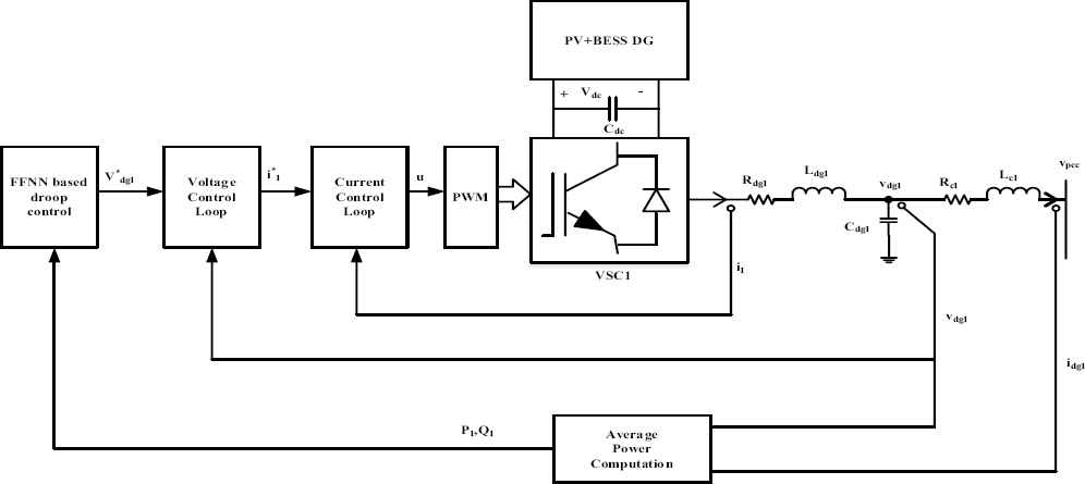
Control structure of VSC1
The outer power control loop is used to set the magnitude and frequency of the fundamental component of VSC’s output voltage. Here, the FFNN based droop control is used to perform this control and it is briefly explained in section 5. The output reference voltage generated by the power control loop acts as an input to the voltage control loop. The voltage control loop is used to generate the reference current signals for the innermost current control loop. The current control loop process these reference current signals to generate switching pulses for the VSC switches. The equations representing the current and voltage dynamics of the VSC1 power circuit are given in Ref. 24 and it is used here to design the control circuit. Similarly voltage control loop and current loop equations are adopted here. The tuned controller values and filter component values are given in Table 1.
4. Generalized Droop Control
In islanded microgrid, droop control is generally used to achieve proper power sharing between DG units6. With this control method, the DG’s can meet the load requirements in a manner pre-determined by its voltage and frequency droop relations. Consider a simple system as shown in Fig. 5. It shows the equivalent circuit of a DG unit connected to a load at PCC through line impedance ZL∠θ. The real and reactive power flow at point A is given by25,
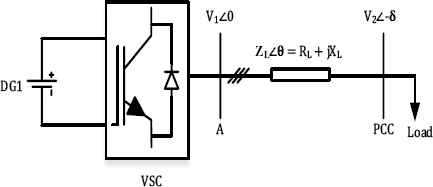
Structure of single DG system
In Refs. 7–12, as discussed earlier either RL or XL is neglected in Eq. (5) and Eq. (6) to develop P-f/Q-V or P-V/Q-f droop relations. However, in general case, both RL and XL have to be considered. For this purpose, droop control based on frame transformation is proposed in Ref. 13, in which a transformation matrix with angle θ which is dependent on the RL/XL ratio of the line, is used to calculate the virtual real and reactive power (Pvir & Qvir). It is given by,
5. ANN Based Droop Control Approach
Recently, intelligent techniques like ANN, fuzzy logic and various evolutionary algorithms are widely used to solve various real world and industrial problems like functional prediction, optimization, price forecasting, system modeling etc. as in Ref. 24 and Refs. 27–30. Among various intelligent approaches, ANN plays a significant role in microgrid operation and control31, 32.
In this paper, to overcome the real and reactive power sharing issues of the generalized droop control and to regulate the islanded microgrid voltage and frequency, a new intelligent droop control approach based on ANN is proposed. The FFNN is selected as the network type. The performance of the neural network depends on number of neurons in hidden layer, activation function used by the hidden layer and also on the training algorithm29. The FFNN with an input layer, one hidden layer and an output layer is shown in Fig. 6. The given input signal passes through the network layer by layer. The links between each node are weighted. Here, Wih represents the weight between input and hidden layer, Who represents the weight between hidden and output layer. These weights are adjusted during the training process. The hidden layer neurons uses nonlinear tangent-sigmoid activation function and the output layer neuron uses pure linear activation function. The output of the hidden layer neurons are mathematically represented as30,
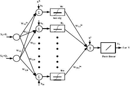
Structure of FFNN
To train the FFNN based droop controller, a simple single DG microgrid system as in Fig. 5 is considered. The line parameters are given in Table 1 and the load change scenario for FFNN training is given in Table 2. For simulating the single DG system, generalized droop control equations given by Eq. (13) and Eq. (14) is used to generate the reference voltage and frequency. The input and output data sets are collected by considering different loading conditions. These data sets are used to train the FFNN. The FFNN has input layer consists of two neurons (one for Pi and one for Qi), hidden layer consists of 10 neurons and an output layer (for f or V). Hence, two FFNN are used (one for generating the voltage reference and the other for generating frequency reference). The FFNN is trained using LM algorithm. The training process is carried out using Matlab/Neural network toolbox. Totally, 12000 sets of input and output data sets are collected from the single DG system and used here to train the network. The FFNN training process comprises three stages namely:
- (i)
Training process: 70% of training data are used for training purpose.
- (ii)
Validation process: 15% of training data are used for validation purpose.
- (iii)
Testing process: Remaining 15% data are used for testing the network.
| Time (in seconds) | P demand (kW) | Q demand (kVAr) |
|---|---|---|
| 0 – 0.15 | 5 | 1.25 |
| 0.15 – 0.35 | 9 | 2.25 |
| 0.35 – 0.55 | 6 | 1.75 |
| 0.55 – 0.75 | 8 | 2.25 |
| 0.75 – 0.95 | 4 | 1.25 |
| 0.95 – 1.2 | 2 | 0.75 |
Load change scenario for FFNN training.
Fig. 7 – 8 shows performance plot and regression plot of the training process. Fig. 7 shows that, there is a gradual reduction in the mean square error for each epoch and finally the mean square error reaches the minimum value of 0.000442 at 652nd epoch. In other words, we can say that, the network starts to learn from the training data sets and finally it completes its learning process to map the input and output values at epoch 652. From the regression plot shown in Fig. 8, with the help of correlation coefficient value (R), it can be seen that FFNN is trained effectively for the given training data sets. The validation, testing and overall performance of the network is also found to be satisfactory (If R=1, it implies perfect correlation). After effective training process, the performance of the proposed FFNN controller is validated by implementing the trained network to an islanded microgrid system under consideration.
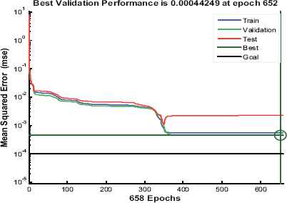
Performance plot of FFNN
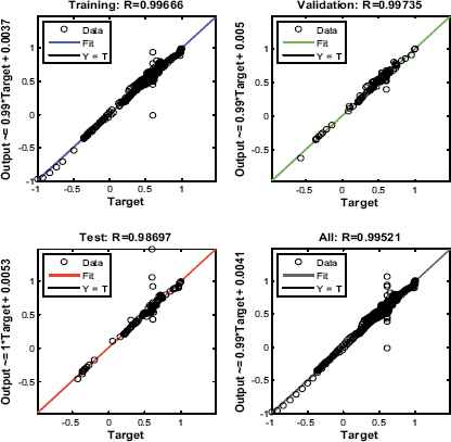
Regression plot of FFNN
6. Results and Discussion
The simulation of the proposed islanded microgrid system as shown in Fig. 1 is carried out using Simpower system toolbox of Matlab. The system is simulated under varying irradiation level and under different loading scenarios. The various system parameters and the controller parameters are given in Table 1.
The load change scenario for the microgrid system is given in Table 3. To show the performance of the proposed ANN based droop control technique over the generalized droop control, necessary results are compared.
| Time (in sec) | P demand (kW) | Q demand (kVAr) |
|---|---|---|
| 0 – 0.15 | 9.5 | 2.4 |
| 0.15 – 0.35 | 15.5 | 3.1 |
| 0.35 – 0.55 | 11.5 | 2.4 |
| 0.55 – 0.75 | 14.5 | 3.1 |
| 0.75 – 0.95 | 8 | 2.4 |
| 0.95 – 1.15 | 4 | 1.5 |
| 1.15 – 1.35 | 13 | 1.9 |
| 1.35 – 1.5 | 9.5 | 1.7 |
Load change scenario for the microgrid system.
The irradiance level is considered to be varying as shown in Fig. 9. Fig. 10 shows the output power of PV, BESS and SOFC system. It can be seen that the output power of PV system is varying according to change in irradiance level. The output of PV system generates its rated power when the irradiance level is at 1000W/m2. Also it can be seen that, when there is excessive power from the PV unit or during lower load demand (during t =0.95s − 1.15s), the excessive power is stored in the BESS. During this period, the BESS power is negative. Similarly, when the output power from PV is low or during higher load demand, the deficit power is supplied by the BESS. During this time period, the output power of BESS is positive. Thus, even though the output power of PV system is intermittent in nature, the power balance in the hybrid unit (DG1) is achieved with the help of BESS.
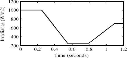
Solar irradiation level
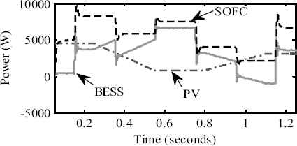
Power output of DG units
The corresponding battery output voltage and current waveforms are shown in Fig. 11. It can be seen that, while BESS is in charging mode the current magnitude is negative while the current magnitude is positive in discharging mode.
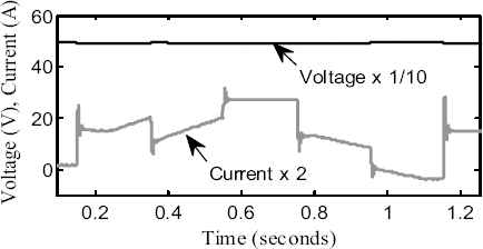
Battery output voltage and current
The dc-link voltage of VSC1 and VSC2 are shown in Fig. 12. It is seen that the dc-link voltage is maintained constant at its reference value (700V) under all conditions.
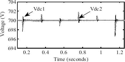
DC-link voltage of VSC’s
The real power output of VSC1 and VSC2 obtained using generalized droop control and FFNN based droop control is shown in Fig. 13. Fig. 13 (a) shows that, initially the generalized droop controller shares equal amount of real power between DG1 and DG2. After the load change (at t=0.15s), there is small sharing error in the real power. From fig. 13 (b), it can be seen that the proposed intelligent droop control method performs better than the generalized droop control by accurately sharing equal amount of real power between the DG units during this time period. Though the real power sharing accuracy of FFNN based droop control is more over similar to that of generalized droop control method, the performance of the proposed method can be clearly seen from the reactive power sharing graphs as shown in Fig. 14. It can be clearly seen that, generalized droop control fails to share the actual reactive power demand among the DG units as shown in Fig. 14 (a).
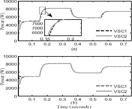
Real power output of VSC’s: (a) Generalized droop control (b) FFNN
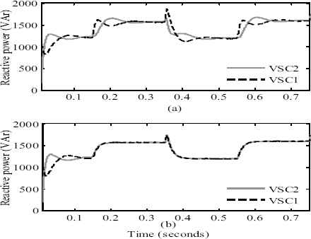
Reactive power output of VSC’s: (a) generalized droop control, (b) FFNN
It is because, the output impedance seen by the VSC1 and VSC2 during load change is slightly different and it leads of voltage difference between the two VSC’s and hence the reactive power sharing accuracy deteriorates. But, the proposed intelligent approach overcomes this drawback by sharing the actual reactive power demand equally among the DG units as shown in Fig. 14 (b). Hence it can be concluded that, by effective training of FFNN, the sharing issues in the generalized droop control can be solved. The total real and reactive power output at PCC is shown in Fig. 15.
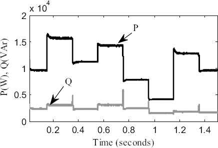
Total real and reactive power output at PCC
Besides achieving proper power sharing, the proposed FFNN based droop control method simultaneously controls the islanded microgrid voltage and frequency within the limits (0.95 p.u to 1.05 p.u for voltage; 49.5Hz to 50.5Hz for frequency) even during disturbances. The output voltage magnitude (phase to ground) and the actual three phase voltage waveforms of VSC1 and VSC2 are shown in Fig. 16.
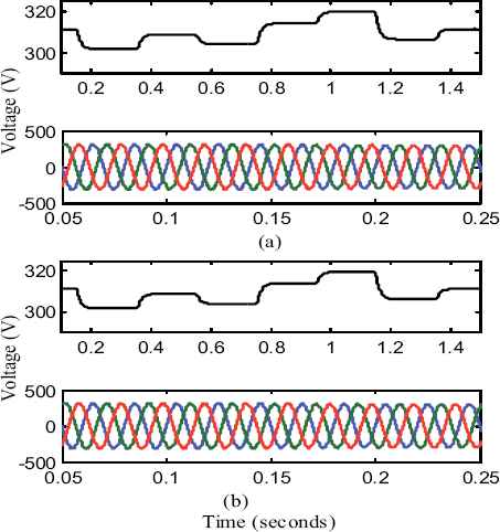
Voltage magnitude and three phase voltage of: (a) VSC1, (b) VSC2
Similarly, the output frequency of VSC1 and VSC2 are shown in Fig. 17. It can be seen that, the voltage and frequency are maintained within the acceptable limit. From this, it can be concluded that the islanded microgrid voltage and frequency are controlled effectively by the proposed method and it performs well under all scenarios (i.e., during sudden load changes and during change in irradiance level).
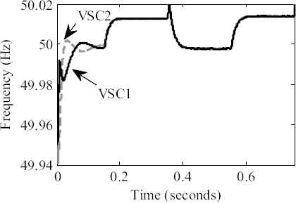
Output frequency of VSC1 and VSC2
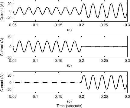
Output current: (a) VSC1, (b) VSC2, (c) current sharing error
To validate the performance of the proposed ANN based droop control method, the results are compared with the existing literature14. For this purpose, the line and load data available in Ref. 14 is considered. The steady-state current sharing error between the two VSC’s is taken as the performance index to show the power sharing accuracy of the proposed method. The output current of VSC’s and the current sharing error between the two VSC’s are shown in Fig. 18. It can be noted that the steady state current sharing error is around 0.3A when both VSC’s are supplying the load demand (until t=0.2s). The results are shown in Table 4. From the results it can be noted that, while considering the complex nature of line impedance, the proposed ANN based droop control method provides better power sharing with reduced current sharing error between the VSC’s than the existing methods.
7. Conclusion
The operation and control of the islanded microgrid system using FFNN based droop control is studied and simulated. In this work, instead of assuming ideal sources as DG units, the actual mathematical models of PV system, BESS and SOFC system are developed and controlled to realize the microgrid system. To overcome the drawback of power sharing issues in generalized droop control technique, a new approach based on FFNN is proposed. The FFNN is trained using data sets collected from a simple single DG system. To test and validate the performance of the trained FFNN controller, it is applied to the proposed two DG microgrid system. From the power sharing graphs, it can be concluded that the proposed method overcomes the drawback of generalized droop control by properly sharing the actual amount of real and reactive power between the DG units while considering the complex nature of the line impedance. Also, it effectively controls the microgrid voltage and frequency under all the conditions. In future, this work can be extended further by applying the ANN based droop control technique to a network of microgrids with large number of DG units. Also, secondary control techniques can be implemented in addition to the primary control to provide frequency and voltage restoration.
Acknowledgements
The authors would like to thank the authorities of Annamalai University for carrying out this research work in their laboratories.
References
Cite this article
TY  - JOUR
AU  - T. Vigneysh
AU  - N. Kumarappan
PY  - 2016
DA  - 2016/09/01
TI  - Artificial Neural Network Based Droop-Control Technique for Accurate Power Sharing in an Islanded Microgrid
JO  - International Journal of Computational Intelligence Systems
SP  - 827
EP  - 838
VL  - 9
IS  - 5
SN  - 1875-6883
UR  - https://doi.org/10.1080/18756891.2016.1237183
DO  - 10.1080/18756891.2016.1237183
ID  - Vigneysh2016
ER  -