
Solving MTU Mismatch and Broadcast Overhead of NDN over Link-layer Networks
- DOI
- 10.2991/ijndc.k.200213.001How to use a DOI?
- Keywords
- Named data networking; NDN link-layer; information centric networks; broadcast overhead; MTU mismatch
- Abstract
Named Data Networking (NDN) has been considered as a promising Internet architecture for the future data-centric communication. In particular, NDN over link-layer networks would cut off the overheads of Transmission Control Protocol/Internet Protocol (TCP/IP), and enhance the efficiency of data distribution. However, there are two main unsolved issues for the NDN link-layer, namely broadcast overhead and Maximum Transmission Unit (MTU) mismatch. In this paper, we have therefore designed and implemented an NDN Neighborhood Discovery Protocol, named NDN-NDP, to enable a unicast data transmission over the link-layer. Furthermore, our NDN-NDP has included a negotiation mechanism to fix the MTU mismatch issue. In comparison to previously proposed NDN link-layer technologies, we can fix both MTU mismatch and broadcast overhead problems. Through emulation and experiments on a test-bed, we have also compared our NDN-NDP with the Link-layer Protocol for NDN (NDNLP), which is the most widely deployed NDNLP. From our experiments, NDN-NDP can efficiently fix MTU mismatch and broadcast overhead issue.
- Copyright
- © 2020 The Authors. Published by Atlantis Press SARL.
- Open Access
- This is an open access article distributed under the CC BY-NC 4.0 license (http://creativecommons.org/licenses/by-nc/4.0/).
1. INTRODUCTION
Named Data Networking (NDN) [1,2] is one of the future internet architectures using the data centric network model. It is a proposal of the Information Centric Network (ICN) architecture, defined by the Internet Research Task Force (IRTF) [3]. NDN is expected to be more efficient for data distribution. For NDN deployment, it can be implemented on top of the current Transmission Control Protocol/Internet Protocol (TCP/IP) stack, or deployed directly over a link-layer network without the TCP/IP protocol stack. NDN over the TCP/IP stack would make NDN possible while the old internet is still running. However, NDN over the link-layer will cut off TCP/IP overhead.
Several protocols for NDN or ICN over the link-layer have been proposed, such as Link-layer Protocol for NDN (NDNLP) [4], Fragmentation with Integrity Guarantees and Optional Authentication (FIGOA) [5], ICN “Begin–End” Hop-by-Hop Fragmentation (BEF) [6], and On-broadcast Self-learning (OBSL) [7]. However, they still face two major challenges, namely broadcast overhead and Maximum Transmission Unit (MTU) mismatch. First, the previously proposed NDNLPs have mainly relied on a broadcast scheme that could drastically increase network overhead. Although a mechanism to create unicast faces over an NDN link layer has been recently proposed [7], it still needs a manual configuration. There has been so far no proper mechanism to manage unicast faces. Second, NDN over link-layer networks should also support a heterogeneous network environment. In such an environment, MTU mismatch is a serious problem, causing transmission failure.
In this paper, a Neighborhood Discovery Protocol for NDN, named NDN-NDP, has been proposed to solve the previously described problems. The NDN-NDP focuses on creating and managing unicast link-layer faces to reduce the number of broadcast packets. In addition, an Adaptive MTU (aMTU) has also been designed into NDN-NDP to solve the MTU mismatch problem. Our NDN-NDP has been implemented by extending Named Forwarding Daemon (NFD) modules [8]. Performance evaluation has been done using a Common Open Research Emulator (CORE) [9] and a test-bed. Experimental results have demonstrated that NDN-NDP can solve the MTU mismatch issue. It also reduces delay and the number of unsatisfied interest packets. Furthermore, NDN-NDP can increase network throughput. So, NDN-NDP effectively enhances the NDN over link-layer networks.
The rest of this paper is structured as follows. Section 2 summarizes NDN concepts and mechanisms. Problems and motivations are discussed in Section 3. Section 4 explains the design and implementation of our NDN-NDP. In Section 5, the experiments on MTU mismatch problems are presented. The experiments on broadcast overhead problem are discussed in Section 6. In Section 7, we discuss and compare our NDN-NDP with related work. In the last section, the conclusions of this work are given.
2. NDN CONCEPTS AND MECHANISMS
In this section, we briefly introduce an overview of NDN architecture [1,2], including NDN model, NFD, face system, and NDN over link-layer networks.
2.1. Named Data Networking Model
Named data networking is a future internet model using an information centric paradigm. It is actually a variant or a proposal of ICN architecture, defined by the IRTF. There are also other proposals of ICN architecture, such as Content Centric Network (CCN) [1], Data-Oriented Network Architecture (DONA) [10], Network of Information (NetInf) [11] and so on. Comparing with the current internet model, NDN and other ICN proposals would provide more efficiency for information distribution. Two types of packets, namely interest and data, have been used in this model. The interest packet is sent by a consumer (aka., receiver), to request a specific content from a content producer. This requested content is referred by a unique name. It is called a named prefix. To fetch the content, the interest packet follows name-routing paths toward the producer. The data packets, carrying the requested content, are then delivered to the consumer. These data packets are originated from the producer, and then may be cached in any intermediate NDN forwarders (i.e., routers) in a reverse path of the interest packet.
2.2. Named Forwarding Daemon
Named Forwarding Daemon [8] is the process of an NDN forwarder, acting as an intermediate node between consumers and producers. It plays a key role to forward interest and data packets in NDN networks. NFD has been implemented with three main components, namely Content Store (CS), Forwarding Information Base (FIB) and Pending Interest Table (PIT). When an incoming interest packet arrives, CS is searched for the desired content. If the content exists, NFD then immediately forward data packets of the desired content from CS to the consumer. Otherwise, NFD searches PIT to check whether the interest packet of the desired content has already been forwarded toward a content producer. If so, the NFD aggregates the interest packet into the transient PIT. In case that CS and PIT have been missed, FIB will be used to select routing paths to fetch the desired content. The content producer generates data packets, and returns them in a reverse path to the consumer. On the reverse path back to the consumer, the data packets may also be cached in the CS of the intermediate nodes. In addition, these data packets have been digitally signed to ensure data integrity.
2.3. Face System
To forward NDN packets, NFD abstracts lower-level network mechanism as faces. So, NDN Face System (FS) [8] is a crucial element to identify a communication link. The NDN community uses the term face instead of interface since NDN packets are not only forwarded over hardware network interfaces, but also exchanged directly with application processes within a machine [1]. An NDN face is identified by its face ID (FID). It is represented as a map of remote Uniform Resource Identifier (URI) to a local URI with some parameters, as shown in Figure 1.
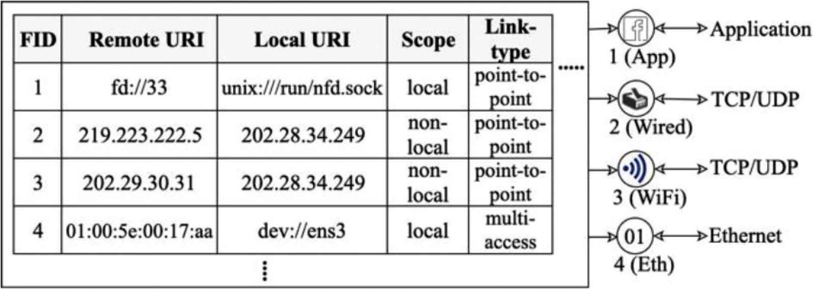
A sampled face table.
Figure 1 represents a sampled face table, maintained at each node. The FID of 1 is an example of application process faces. The FID of 2 is a sampled face of NDN over the TCP/IP stack. This face uses the User Datagram Protocol (UDP) as a communication link. It represents a map of remote URI, locating over an IP address of 219.223.222.5, to a local URI, locating over an IP address of 202.28.34.249. This face is then mapped to remote named-prefixes by FIB (as shown in Figure 2) to specify routes to fetch some specific contents.
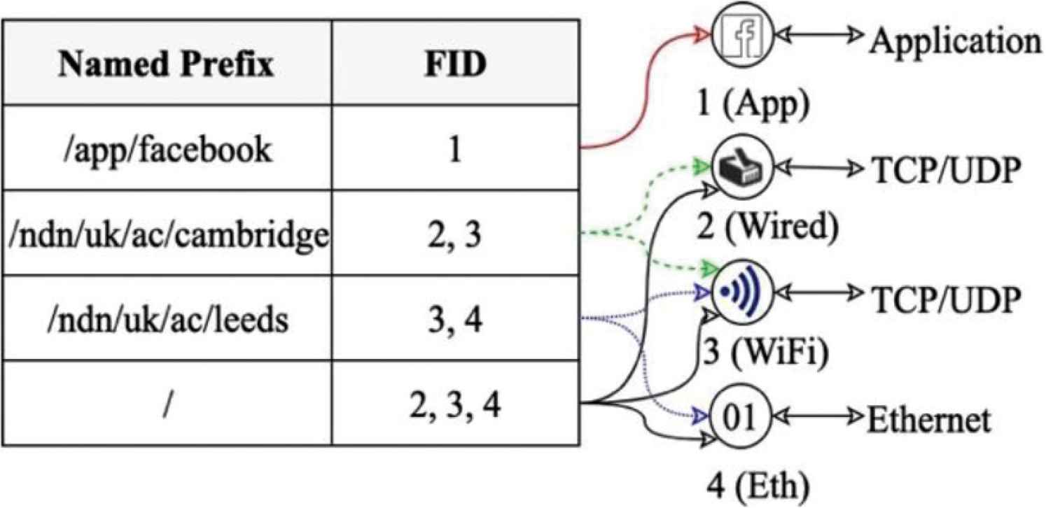
An example of FIB.
The FID of 4 is a face for NDN over link-layer networks. It maps a remote URI, “ether://[01:00:5e:00:17:aa]”, to a local URI, “dev://ens3”, which is an Ethernet local face. To send and receive interest and data packets in NDN over an Ethernet link-layer network, a multicast address of 01:00:5e:00:17:aa is generally used, as shown from the last sampled face (FID = 4). This address is known as “the default ICN Multicast Address (ICN-MCAST)”. All NDN-enabled devices on the Ethernet link-layer network must join to this multicast address. So, this technique is actually broadcasting to all NDN-enabled devices on the link-layer network. This paper calls this face as “NDN Link-layer Broadcast Face (NLBF)”. Deploying the NLBF can flood the link-layer network, causing broadcast overhead (further discussed in Section 3.2). To avoid the overhead, it is very necessary to design new link-layer unicast faces for NDN over link-layer networks. During finishing our experiments and on the process of writing this paper, we have found that the NDN community has initially proposed mechanism to manually create unicast faces. However, there is still no mechanism to automatically manage the NDN unicast faces.
2.4. NDN over Link-layer Networks
To deploy NDN directly over link-layer networks, a Hop-By-Hop Fragmentation and Reassembly (HBH-FR) [4] technique is used. HBH-FR generates frame-packets according to the MTU of the local Network Interface Card (NIC), and broadcast them over the link-layer networks.
To avoid NDN broadcast scheme, a link-layer unicast face must be created and inserted into a face table. This process requires a target Media Access Control (MAC) address, and is still an unsolved issue in NDN over link-layer networks.
Deploying NDN directly over link-layer networks without the TCP/IP protocol stack would reduce huge overheads. This overhead cut-off provides an efficiency for data distribution and would help many modern network applications evolve rapidly. However, the design of NDN over link-layer networks is still at its infant-phase. NDNLP [4], FIGOA [5] and BEF [6] are among the initially proposed NDN link-layer protocols. These protocols still suffer some problems, discussed in the next section.
3. PROBLEMS AND MOTIVATIONS
Previous proposals of NDN link-layer protocols still face two main problems, namely MTU mismatch and broadcast overhead, as explained in the following sections.
3.1. MTU Mismatch
Maximum Transmission Unit is the largest possible payload of frame-packets that can be sent in a particular link-layer network. In general, the current Internet uses a standard Ethernet’s MTU size of 1500 bytes, almost universally across networks. However, Ken and Monkul [12] have pointed out that various network devices on the Internet have different MTU sizes, varying from 127 bytes for an Internet of Thing (IoT) [13] to 65820 bytes for a fibre [14]. For example, constrained low-energy links in IoT networks have very small MTUs [13,15]. The MTU size is only 127 bytes for IEEE 802.15.4-2006 [16]. In such a heterogeneous MTU environment, if a sender tries to transmit a packet too big for the receiver to cope with, the transmission could fail. This problem is called “MTU mismatch”.
To solve MTU mismatch problem for the current Internet, there have been several proposals. For example, IPv6 Path MTU discovery [17] has been proposed to find the minimum MTU on the transmission path. Kushalnagar et al. [18], have also proposed an adaptation layer between a link-layer and a network layer to mitigate the problem. For NDN, several studies have also pointed out that the MTU mismatch would cause a serious problem [5,19].
3.2. Broadcast Overhead
To send and receive interest and data packets in NDN over a link-layer network, the broadcast face or NLBF (as mentioned in Section 2.3) is deployed. Broadcasting on the link-layer helps simplify content distribution. This technique is also useful for reducing the management of remote destination MAC addresses. However, broadcasting could severely flood NDN local devices, causing network overheads. So, to avoid the broadcast overhead, a unicast scheme for NDN over link-layer networks should be designed and implemented.
To create a unicast face in NDN, a remote destination MAC address must be learned and mapped. Recently, Shi et al. [7], has proposed OBSL mechanism to learn and create a unicast face. Their mechanism floods the first interest packet to observe where a returned data comes from, and adds the unicast face over IP. However, this solution cannot work in a native link-layer network. The NLBF is still used in such a case. So, the broadcast overhead is still occurred in the NDN link-layer networks even with the OBSL mechanism.
4. DESIGN AND IMPLEMENTATION
To solve the MTU mismatch and broadcast overhead, we propose a novel NDN-NDP for NDN link-layer, and name it “NDN-NDP”. Our NDN-NDP includes the following mechanisms, namely NDN Link-layer Unicast Face (NLUF), NDN-NDP operations, and aMTU. The details of our design and implementation are explained in the following sub-sections.
4.1. NDN Link-layer Unicast Face
In NDNLP [4], NDN Link-layer Broadcast Face (NLBF) is commonly used for communicating over NDN link-layer networks. So, we propose a new NLUF, that supports unicast transmission over link-layer networks. This NLUF provides the unicast face for OBSL [7] in link-layer networks. In addition, not only NLUF can reduce the broadcast overhead, but it can also fix the MTU mismatch problem. The details of creating and deploying NLUF are discussed as follows.
- (i)
First of all, an aMTU table is created and maintained at each node, to record an aMTU size of each face (in the face table), as shown in Figures 3 and 4. After that, the face MTU of each NLUF is set to aMTU to avoid the MTU mismatch. The details of an adaptive MTU selection is further discussed in Section 4.3.
- (ii)
In order to support unicast communication over link-layer networks, we have to map a destination named prefix to a destination unicast MAC address. To do so, we use NLUFs and FIB as follows. At each NDN node, an NLUF is created after learning the destination MAC addresses. This NLUF maps a destination unicast MAC address with a link-layer local face in the face table (as shown in Figure 3). After that, NLUF may be mapped further to named prefixes in FIB (as shown in Figure 5).
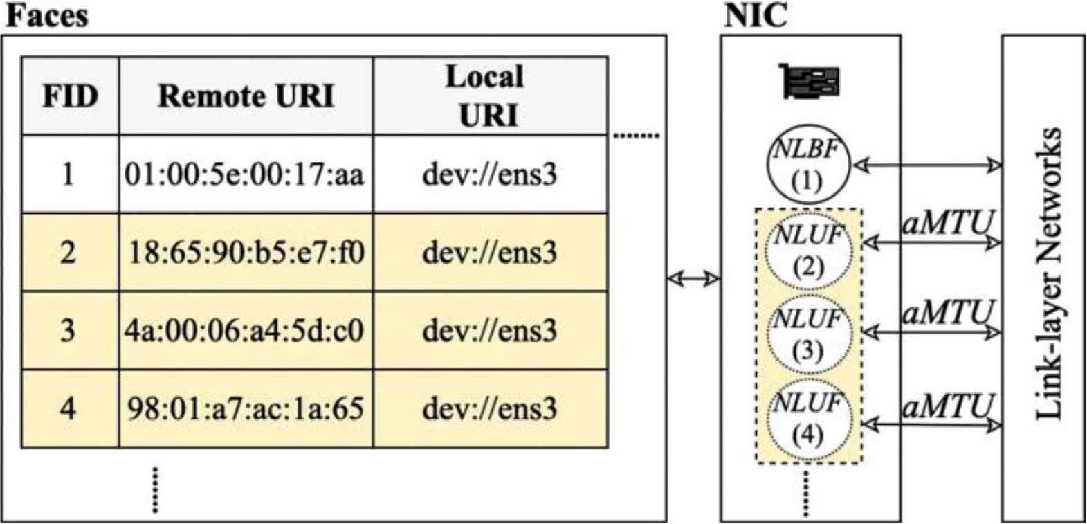
A face table.
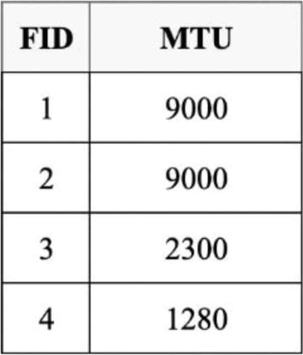
An adaptive MTU table.
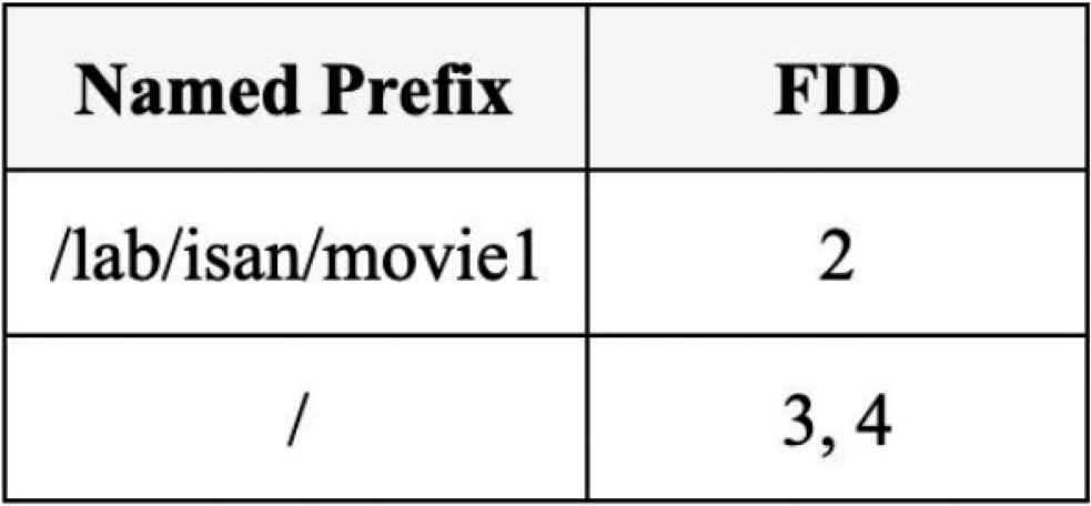
Forwarding information base.
Examples are shown in Figures 3–5. The face, of FID = 2, is an NLUF. It maps a destination MAC address of 18:65:90:b5:e7:f0 to an Ethernet local face (dev://ens3), as shown in the face table (in Figure 3). This face uses a very big aMTU size of 9000 bytes (as shown in the adaptive MTU table, in Figure 4) to transfer a movie. In FIB (shown in Figure 5), this NLUF is further mapped to a destination named-prefix of “/lab/isan/movie1”.
The NLUF, with FID = 4, is mapped from an Ethernet local face (dev://ens3) to a destination MAC address of 98:01:a7:ac:1a:65, which is the MAC address of a forwarder (router). The MTU for this NLUF is 1280 bytes. In FIB, this NLUF is further mapped to a destination named prefix of “/”, which is the default named prefix. For any desired named-prefixes with no route (in FIB) to data packets, this NLUF (FID = 4) will be chosen to forward an interest packet to the forwarder. The forwarder then forward the interest packet further to fetch the contents from outside Local Area Network (LAN).
4.2. NDN-NDP Operations
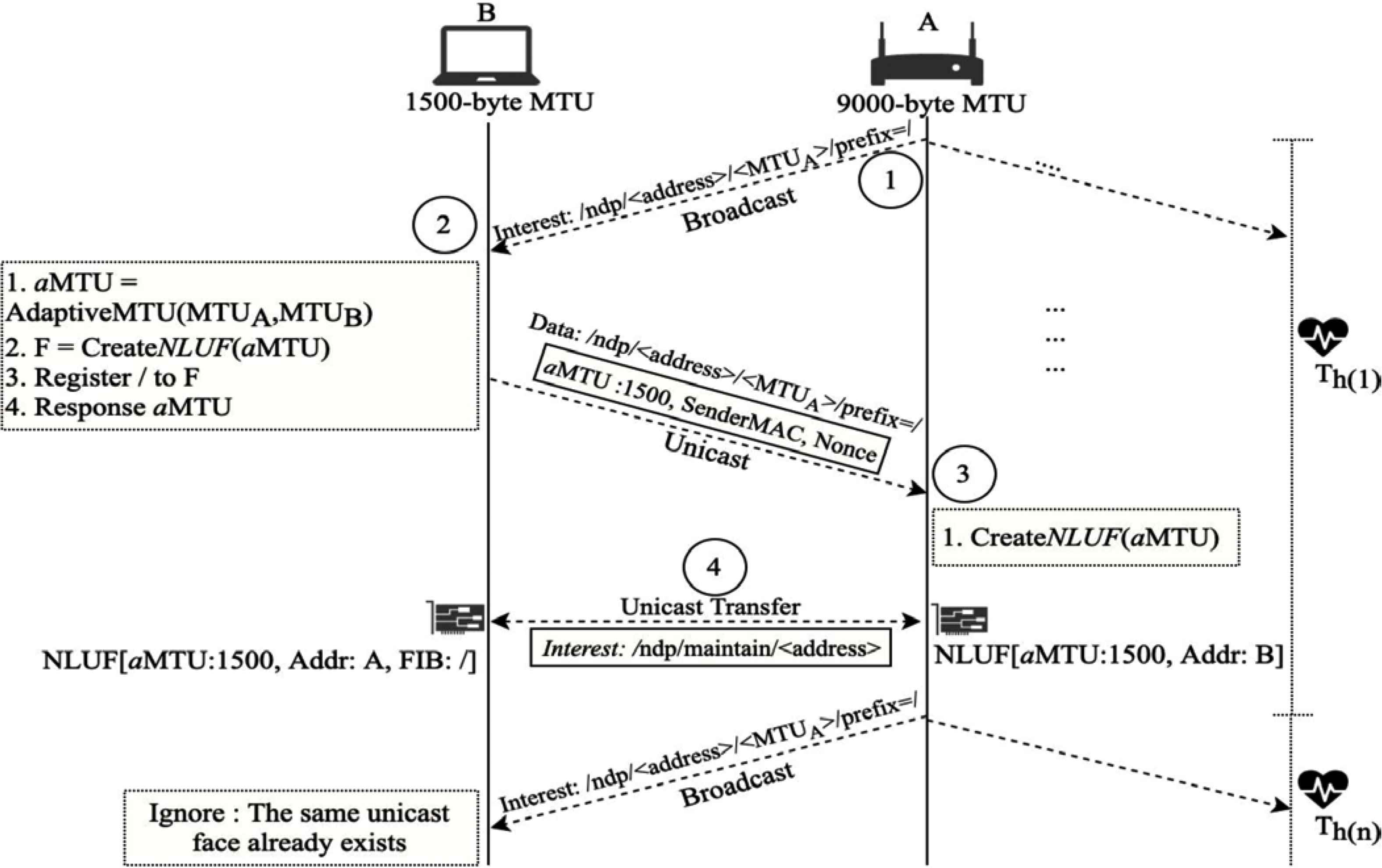
NDN-NDP is deployed to learn the destination MAC addresses, and map a destination named prefix to destination MAC addresses. The overall operations of NDN-NDP are illustrated in Figure 6. From the figure, there are several end-user devices on a link-layer network, including node A and node B. Node A and B have 9000 and 1500 bytes of MTUs respectively. Node A is an NDN forwarder. The NDN-NDP operations can be explained as the following steps:
- (i)
Each node, for example node A, periodically broadcasts a special interest packet, named Neighbor Discovery Interest (NDI), to all NDN local devices on the same link-layer network at every heartbeat interval (Th). The “name” field of this NDI consists of an NDN-NDP identifier, a device’s MAC address, an interface MTU, and an optional named prefix (as shown in the step-1 of Figure 6). For example, an NDI name is “/ndp/c0:c1:c0:13:fb:64/9000/prefix=/ndp” is an NDN-NDP identifier. c0:c1:c0:13:fb:64 presents the MAC address of node A. It is followed by the MTU of node A, which is 9000 bytes. At the end, “prefix=/” is the default named prefix, showing that node A can act as a forwarder to fetch the internet contents by forwarding interest packets further. If node A is a producer, the prefix will show the named prefix of node A, for example “prefix=/ndn/uk/ac/leeds/ node/A”. However, if node A is a consumer, this prefix part will not exist.
- (ii)
Neighbor Discovery Interest from node A will arrive at all other NDN nodes in its link-layer network. Each node that received NDI from node A then responds as follows. For instance, node B, after receiving NDI from node A, will choose an aMTU from the minimum between its MTU and node A’s MTU. From this example, aMTU is 1500 bytes. Node B can then create an NLUF to node A with the MTU size equal to aMTU. After creating the NLUF corresponding to the NDI of node A, node B will ignore all incoming NDIs from node A. Yet, it will deploy and maintain the created NLUF for communicating with node A.
- (iii)
If a named prefix (in this example, “/”) is attached in NDI, node B will map the NLUF to the named prefix in FIB. For receiving NDI without a prefix part, neighbor nodes will create NLUF without adding any named prefix to FIB.
- (iv)
Furthermore, node B responds by sending a Neighbor Reply Data (NRD) packet back to node A via the NLUF. The name field of NRD is the same as the received NDI. This NRD contains two important information for node A: aMTU and the MAC address of node B. NRD must also be digitally signed in order to be validated in the next step.
- (v)
After receiving NRD from node B and validating its legitimacy, node A creates a new NLUF to node B, as shown in step-3 in Figure 6. This NLUF has its MTU size equal to aMTU.
- (vi)
After NLUFs between node A and B have been successfully created, the NDN communication between these two nodes over the link-layer network can be done in the unicast mode. An idle NLUF for a period of time will be destroyed, assuming that the link has been disconnected.
- (vii)
To keep NLUFs alive, both A and B maintain their NLUFs by sending a special interest message (called “NLUF maintenance message”) to each other for every Th. Without receiving the NLUF maintenance message for a certain period of time (t), the NLUF record will be deleted.
NDN-NDP operations.
4.3. Adaptive MTU
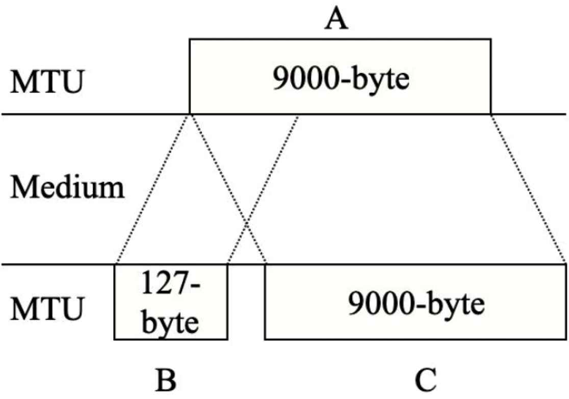
To solve the MTU mismatch, this work proposes to use the minimal hop-by-hop MTU between two nodes as an aMTU of their faces. By exchanging NDI and NRD between two nodes in the NDN-NDP operations (as described in Section 4.2), the minimum MTU between them is selected as aMTU for HBH-FR. Figure 7 illustrates an example of aMTU. According to the figure, there are three nodes, including A, B and C. Node A and C supports jumbo-frame [20] MTU of 9000 bytes. Node B is an IoT device, merely supporting MTU of 127 bytes. According to NDN-NDP operations, node A propagates an NDI packet, carrying a device’s MTU. Node B then compares the received MTU with its local NIC’s MTU, and creates an NLUF to node A with an aMTU of 127 bytes. Node B then responses the aMTU value back to inform node A via an NRD. Node A finally creates a new NLUF with the aMTU of 127 bytes to node B. For node A and node C operations, NLUFs will be created by using the same operations as node A and node B, and vice versa.
An example of adaptive MTUs.
4.4. NLUF Security
To avoid a similar Address Resolution Protocol (ARP)-spoof attack in NDN over link-layer networks, a security vulnerability in a classical Ethernet has been explored. From the literature [21,22], ARP-spoof can deviate a communication path to capture and manipulate sensitive information. It finally leads to denied of service attack, replay attack and man-in-the-middle attack. To protect against the similar problem, NDN over link-layer networks needs a verification of interest and data packets before making a unicast as the followings:
- (i)
Signature: The digital signature in an NRD packet must be verified before taking any actions.
- (ii)
Verification: The incoming NRD packet must be corresponded to the outgoing NDI packet. This is done by using a nonce.
- (iii)
Capturing attacks: Unsolicited NRD packets have been analyzed to quarantine a risky behavior of neighbor nodes.
- (iv)
Dropping attacks: By capturing and analyzing unsolicited NRD packets, we use a threshold (T), which is adjustable according to network environment, to recognize undesired behaviors, and drop all NRD packets received from attackers.
Even with the above security procedures, other in-depth security issues would be further studied. It is not in the scope of this paper, but should be done as future work.
4.5. Implementation
We have built our NDN-NDP protocol by extending NFD-0.6.5 [8]. The implementation has been done to handle NDN-NDP operations, aMTU selection and NLUF management. For NDN-NDP packet processing, our extended NFD is compatible with common interest and data packets. An identification of NDN link-layer is defined as 0x8624. The NLUF management is implemented in the NFD Ethernet factory. It connects with the NFD Ethernet transport for multiplexing frame-packets. Finally, validation tests on our implementation have been done extensively.
5. EXPERIMENTS ON MTU MISMATCH PROBLEM
5.1. Experiment Setup
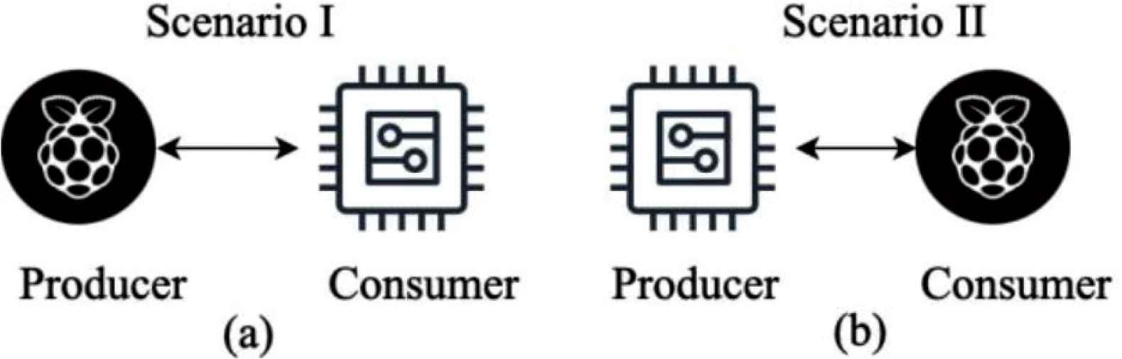
To experiment on the MTU mismatch issue, we have setup a test-bed as shown in Figure 8. An ESP8266 IoT board [23] and a Raspberry PI-3 model B (installed with Ubuntu mate 16.04) are deployed as a producer and a consumer, and vice versa. In Figure 8a, the Raspberry PI-3 acts as the producer, while the ESP8266 acts as the producer in Figure 8b. A micro NFD has been implemented using MicroPython [24] to process basic NDN functionalities for ESP8266 IoT board. NFD version 0.6.5 has been deployed in Raspberry PI-3. Two nodes have been connected to each other using IEEE 802.11n, 2.4 GHz signal.
The test-bed scenario to evaluate MTU mismatch problem. (a) varying producer’s MTU sizes, (b) varying consumer’s MTU sizes.
The details of MTU setting are as follows. In Figure 8a, the ESP8266 IoT board (acted as a consumer) uses the universal 1500-byte MTU. For the producer (Raspberry PI-3), the MTU sizes have been varied as 127, 1500 and 9000 bytes to represent different MTU sizes. The 127-byte MTU represents a small MTU size of several IoT devices [13,15,16]. The 9000-byte MTU represents the jumbo-frame [20]. The 1500-byte MTU represents the Ethernet MTU, which is the most widely deployed MTU size. In Figure 8b, the producer (ESP8266) uses an MTU size of 1500 bytes, while the consumer (Raspberry PI-3) deployed different MTU sizes, 127, 1500 and 9000 bytes respectively.
The objective of our experiments is to observe the MTU mismatch problem by checking the success or failure of data transmission using different MTU sizes between the producer and the consumer. If the MTU mismatch occurs, NDN packets would be dropped and the transmission would fail.
For each experiment, NDN packets are sent continuously for 10 min. To compare our protocol with NDNLP, the experiments have been run twice: one for NDN-NDP and the other one for NDNLP. Moreover, each experiment has been repeatedly run for 30 times to ensure the consistency.
5.2. Experimental Results
The experimental results have shown that NDN-NDP has no problem with the MTU mismatch, while NDNLP has a serious problem with MTU mismatch. As shown in Tables 1 and 2, NDN-NDP can transmit packets successfully for all different sizes of MTUs between the producer and the consumer. Yet, NDNLP has failed in two scenarios due to the MTU mismatch problem. In Table 1, NDNLP transmission is failed when the producer with the 9000-byte MTU size trying to send to the consumer with 1500-byte MTU. In Table 2, NDNLP transmission is also failed when the producer with the 1500-byte MTU trying to send to the consumer with 127-byte MTU. Summarily, NDNLP suffers the MTU mismatch problem. Its transmission will fail if the MTU size of the receiver is smaller than the MTU of the sender. On the other hand, our NDN-NDP has successfully solved the MTU mismatch problem using its adaptive MTU mechanism.
| Producer MTUs (bytes) | The success of transmission | |
|---|---|---|
| NDN-NDP | NDNLP | |
| 127 | Successful | Successful |
| 1500 | Successful | Successful |
| 9000 | Successful | Failed |
Experimental results of scenario I (Figure 8a), a consumer MTU’s size for all cases equals to 1500 bytes
| Consumer MTUs (bytes) | The success of transmission | |
|---|---|---|
| NDN-NDP | NDNLP | |
| 127 | Successful | Failed |
| 1500 | Successful | Successful |
| 9000 | Successful | Successful |
Experimental results of scenario II (Figure 8b), a producer MTU’s size for all cases equals to 1500 bytes
6. EXPERIMENTS ON BROADCAST OVERHEAD PROBLEM
6.1. Experimental Setup
For broadcast overhead, an emulation technique is deployed to evaluate the performance of our protocol. CORE [9] is used to emulate our experimental test-bed. The NFD version 0.6.5 is deployed. Ethernet is used as a link-layer network to handle frame-packets.
For experimental network scenario, a grid topology has been chosen as shown in Figure 9. Three NDN producers, nine NDN forwarders, and five NDN consumers are connected on the topology. P1, P2 and P3 provide NDN contents using ndnputchunks [8]. Five NDN consumers are connected at the R2 forwarder, and simultaneously retrieve data packets from P1, P2 and P3 by sending interest packets through the forwarders to consume all available bandwidth. The experimental parameters are described as follows:
- (i)
Content: A file size to generate NDN data packets is 1 Megabyte. The ndnputchunks has been used to generate these data packets.
- (ii)
Link-speed: All links in the scenario are set to 100 Mbps.
- (iii)
Link-layer protocol: The Ethernet is the only available communication channel in this experiment.
- (iv)
Strategy layer: A self-learning strategy of OBSL [7] is used in NDN strategy layer.
- (v)
Data freshness period: A freshness period of NDN data packets is set to 1 s.
- (vi)
FIB: Due to our multi-hop network scenario, FIB in our experiment nodes have been populated by using self-learning protocol. The first parameter is to use NDNLP to combine with OBSL. The second parameter is to use our NDN-NDP to provide NLUFs for OBSL.
- (vii)
Heartbeat interval (Th): This heartbeat interval is the interval of broadcasting NDI, which is very important to create and maintain unicast faces. By increasing the Th, it is better in terms of broadcast packet reduction. However, too long Th could increase delay for creating unicast faces, and might be unsuitable in terms of network responsiveness. In the other way, too short heartbeat interval could also trigger NDN to create unnecessary broadcast packets. So, we have tested parameter sensitivity for this heartbeat interval, and have found that 1–3 s are suitable for both responsiveness and broadcast overhead. For the experimental results reported in the next section, Th is set to 3 s.
- (viii)
Timeout: Outgoing interest packets that take too long time to response will be terminated. We use the default NFD timeout value (10 s) for our experiments.
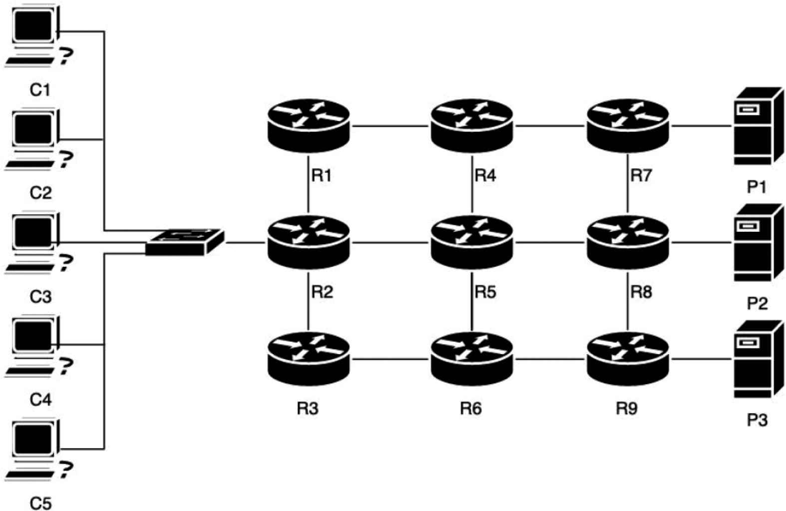
An experimental scenario.
In our experiments, we compare our NDN-NDP with NDNLP, which is the most widely deployed NDN link-layer protocol. OBSL has been also used to support FIB management in the link-layer networks. Each experiment is to download data packets from P1, P2 and P3 for C1, C2, C3, C4, and C5. Moreover, each experiment has been repeatedly run for 30 times. Experimental results are averaged and quoted from the 30 runs with respect to a confidence interval of 95%.
The number of broadcast packets, network throughput, delay and the number of unsatisfied interests are used as our performance metrics. Each metric can be described as follows:
- (i)
Number of broadcast packets: Broadcast packets in an NDN link-layer network are actually the multicast packets, sent over the default ICN-MCAST. By using nfd status report, all incoming interest and data broadcast packets have been counted. This metric indicates broadcast overhead of NDN link-layer networks.
- (ii)
Network throughput: Network throughput is the rate of successful data packets, delivered over the experimental NDN link-layer. It is represented in megabits per second (Mbps). We use ndncatchunk [8] to report the averaged network throughput of our network nodes. This metric indicates the efficiency of NDN link-layer networks.
- (iii)
Delay: Delay is the averaged time from sending interest packets until receiving data packets. It is reported in millisecond (ms) using ndncatchunk report. The lower the delay the better the performance.
- (iv)
Number of unsatisfied interests: The number of unsatisfied interests is used to count outgoing interest packets with no returned data packets. It would indicate the problems of NDN forwarding process, resulting from network broadcast overhead, MTU mismatch, and other problems. The more the number of unsatisfied interests, the worse the performance is.
6.2. Experimental Results
For the broadcast overhead problem, the experimental results for each metric are discussed in the following sub-sections.
6.2.1. Number of broadcast packets
In our experiments, the number of broadcast interest packets and the number of broadcast data packets between NDN-NDP and NDNLP are compared. For NDN-NDP, the number of broadcast packets also includes the extra NLUF maintenance messages and NDIs of our proposed mechanism. The comparative results are given in Figure 10. Summarily, by providing link-layer unicast faces for OBSL, NDN-NDP can help reduce the number of broadcast packets in comparison to NDNLP. For interest packets, NDN-NDP and NDNLP generate approximately 733.6 ± 181.3 and 1403.6 ± 320.9 packets to receive the same amount of data. For data packets, NDN-NDP uses 448.0 ± 50.7 packets, while NDNLP uses 1091.5 ± 236.9 packets. This reduction has mitigated the broadcast overhead, and finally improve overall efficiency. Also, the experimental results have revealed that the NLUF maintenance messages and NDIs of NDN-NDP are acceptable overhead for NDN link-layer networks.
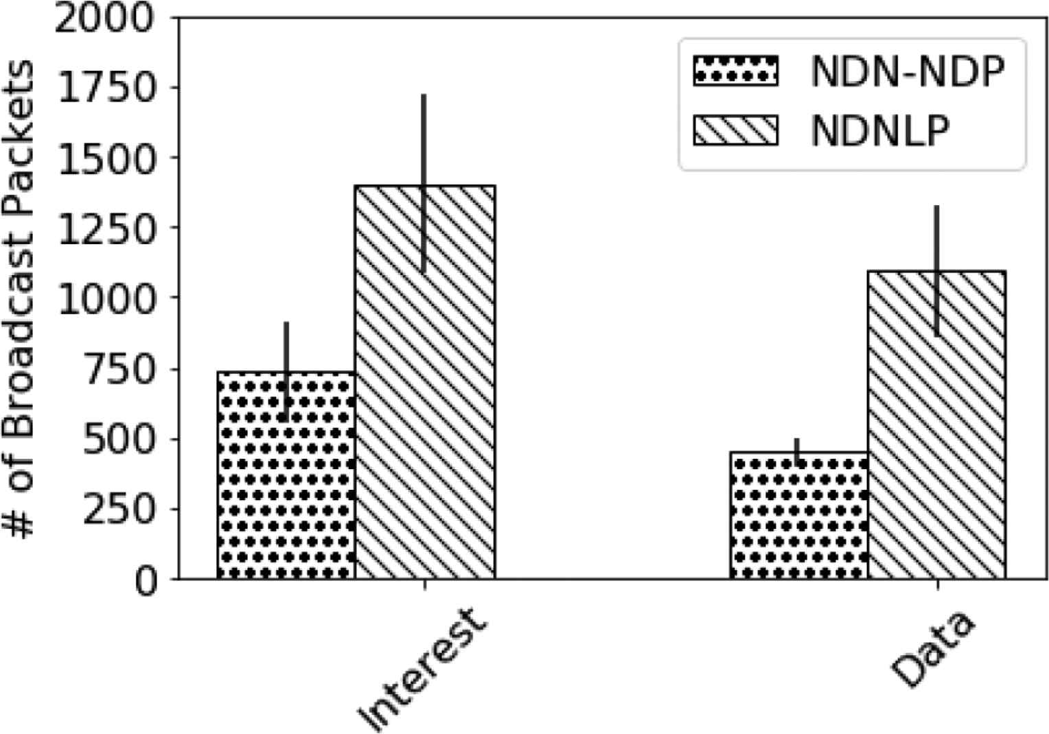
The numbers of broadcast interests and data packets.
6.2.2. Network throughput
Network throughput is potentially influenced by numbers of broadcast packets. Figure 11 compares the network throughput between NDN-NDP and NDNLP for different types of NDN packets. Experimental results have shown that NDN-NDP and NDNLP gain throughput of 10.4 ± 1.8 and 7.2 ± 0.6 Mbps respectively. NDN-NDP utilize the link-layer network more efficiently than NLBF of NDNLP.

Network throughput.
6.2.3. Delay
The delay of NDN-NDP and NDNLP is compared in Figure 12. The experimental results have shown that NDN-NDP consistently incurs less delay than NDNLP. The delay of NDN-NDP as compared to NDNLP’s is 5.9 ± 1.2 and 16.5 ± 1.5 ms respectively. Therefore, the experimental results have pointed that NDN-NDP can reduce delay, which effectively enhance NDN over link-layer networks.
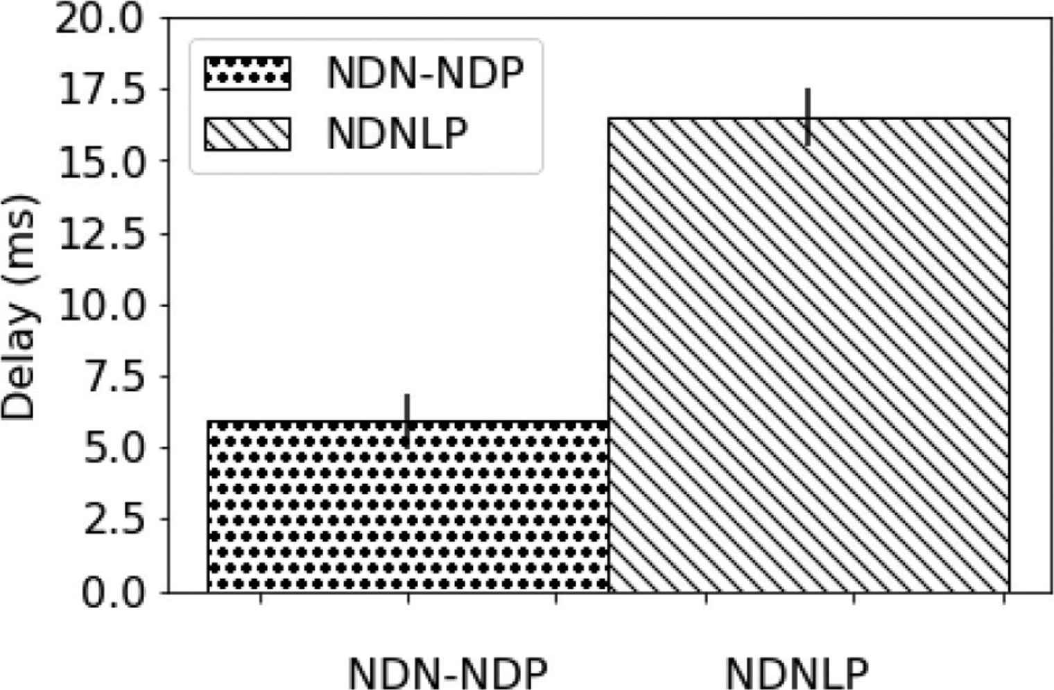
Delay.
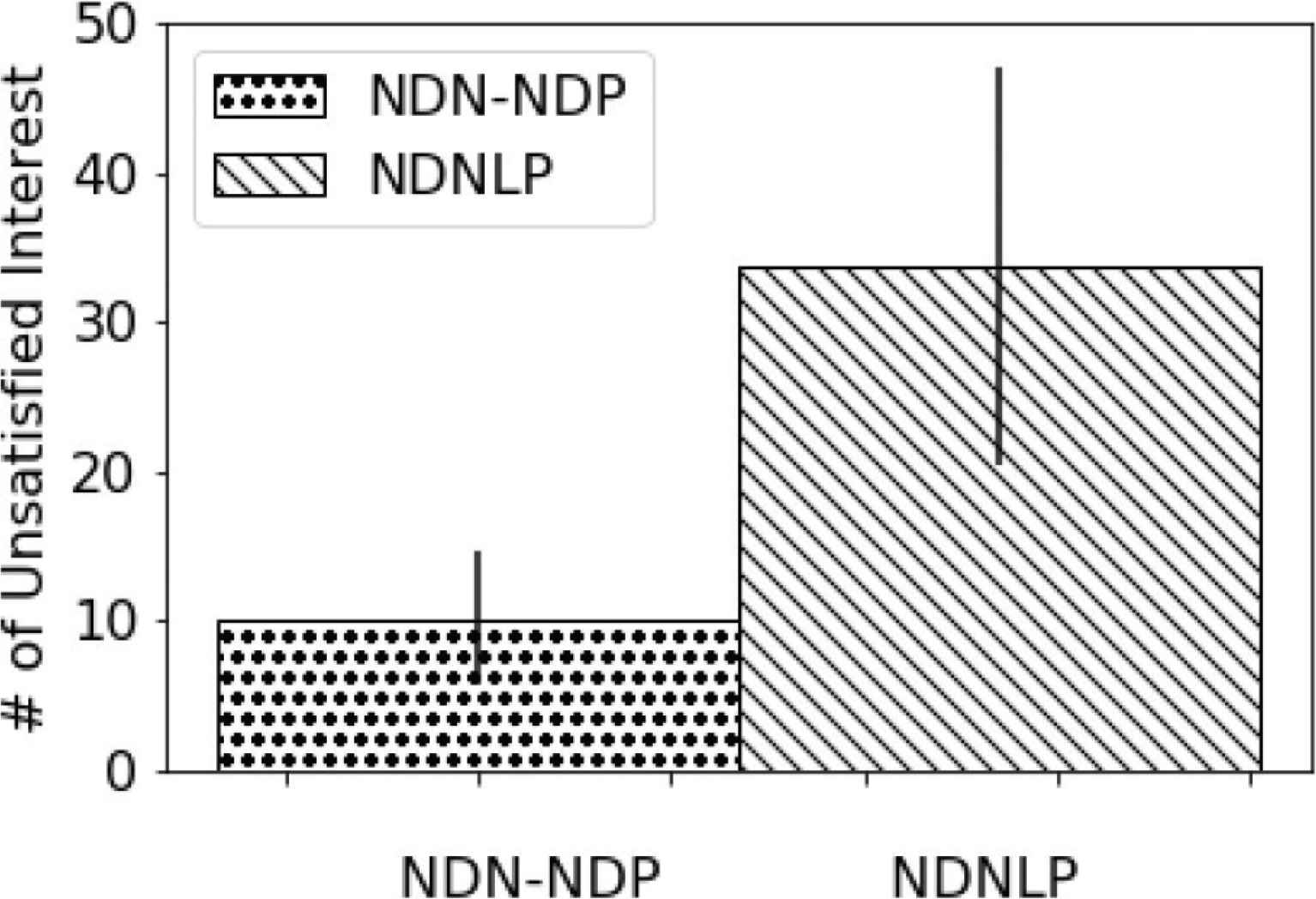
The number of unsatisfied interests.
6.2.4. Number of unsatisfied interests
Named data networking unsatisfied interests are the interest packets that fail to retrieve NDN data packets. From the experiments, the number of unsatisfied interests of NDN-NDP and NDNLP are comparatively counted. As shown in Figure 13, the number of unsatisfied interests of NDN-NDP is 10.1 ± 4.5, while the number of unsatisfied interests of NDNLP is 33.7 ± 13.4. So, the number of NDN-NDP unsatisfied interests is less than the number of NDNLP unsatisfied interests. NDN-NDP explicitly outperforms NDNLP for this metric.
7. RELATED WORK
So far, there have been a few proposed link-layer protocols for NDN and other ICN architectures. However, most of them still suffer broadcast overhead and MTU mismatch problems. In this section, we discuss our work in comparison with other studies in the literature.
Named data networking link protocol is a link-layer protocol for NDN, proposed by Shi and Zhang [4]. Currently, it is the most widely deployed link-layer protocol for NDN. The last version is NDNLPv2. NDNLP relies on multicasting over ICN-MCAST group (MAC Address: 01:00:5e:00:17:aa), which is technically broadcasting to all NDN devices on the link-layer network. Recently, in NFD version 0.6, NDNLP has initially supported a unicast face. Yet, it needs a target MAC address to be mapped with a local network device. So, a learning protocol is required to add the unicast face. So far, OBSL has been proposed by Shi et al. [7] for the learning process. OBSL works in a strategy layer and would be able to turn on to support NDNLP. However, from our investigation, OBSL can only create a unicast face over IP. It is not working for the NDN over a link layer network without TCP/IP. So, the broadcast overhead is still a problem for NDNLP (even with OBSL) for NDN over link layer networks. Furthermore, NDNLP has no mechanism to solve the MTU mismatch problem. In contrast, our NDN-NDP has been designed to avoid the MTU mismatch, and mitigate the broadcast overhead.
A few link-layer protocols have also been proposed for CCN, a variant of ICN. One is Begin-End-Fragment (BEF) by Mosko and Tschudin [6] and the other one is FIGOA by Ghali et al. [5] BEF is the first and most widely deployed link-layer protocol for CCN. Both BEF and FIGOA also rely on multicasting over the ICN-MCAST group, and therefore suffer from the broadcast overhead. In addition, BEF has no mechanism to prevent the MTU mismatch. So, transmission by BEF could be failed in a heterogeneous environment with different node’s MTU sizes.
For FIGOA, the minimum path MTU (μMTU) must be discovered to define the maximum size of interest and data packets to prevent intermediate fragmentation. This idea is similar to the path MTU discovery for IP version 6 [17]. By using the minimum path MTU, FIGOA would not be vulnerable to the MTU mismatch. However, we argue that µMTU of FIGOA would be inefficient in comparison with aMTU of our NDN-NDP. The aMTU of each hop can be bigger than µMTU of the whole end-to-end path. So, the bigger MTU would utilize bandwidth more efficiently. For example, a producer of the desired contents is an IoT zigbee (IEEE 802.15.4) device with 127-byte MTU, located somewhere outside the local network. A consumer is an Ethernet client in our local network, connected to an Ethernet router (or forwarder). Both consumer and forwarder have 1500-byte MTU. In this case, FIGOA will use the µMTU of 127 bytes for all hops. However, for the hop inside the local network, NDN-NDP will use the aMTU of 1500 bytes, thus gaining more bandwidth utilization over this link-layer.
The idea of mapping a named prefix to MAC address and utilizing unicast faces in NDN link-layer has also been introduced by Kietzmann et al. [25] They have investigated the broadcast overhead effects on NDN over link-layer networks, especially for IoT networks. Their study has suggested that “since the broadcast frames are not filtered by common device drivers of the network interface, these frames would be processed and heavily consume the limited hardware resources (such as CPU, memory, energy and so on) of the end devices” [25]. So, the broadcast overhead of NDN link-layer would cause a severe problem to IoTs. Furthermore, their experiments have shown that the number of unsatisfied interests would be reduced by using unicast instead of broadcast in the link-layer. So, they have finally suggested that a named-prefix to link-layer mapping is needed. Yet, this study still leaves the design of solutions as an open research question. Furthermore, this study has not addressed the MTU mismatch issue.
8. CONCLUSION
Named data networking have played a major role to shape the future internet architecture. In particular, deploying NDN directly on top of link-layer networks instead of TCP/IP protocol stack would remove a huge overhead. This overhead cut-off would enhance an efficiency for designing modern network applications. However, NDNLPs are still at their initial phase. Broadcast overhead and MTU mismatch are still their significant unsolved problems. In this paper, a new NDN link-layer protocol, named NDN-NDP, has been proposed to fix the aforementioned problems. By using our HBH aMTU, the MTU mismatch problem can be solved. Furthermore, a performance evaluation via the CORE emulator and a network test-bed have been done on our NDN-NDP in comparison to NDNLP, the most widely used NDNLP. Experimental results have demonstrated that NDN-NDP outperforms NDNLP. First, NDN-NDN can solve the MTU mismatch problem while NDNLP transmission could be failed when facing the MTU mismatch scenarios. Second, by introducing a unicast face, NDN-NDP has enhanced NDN over link-layer networks in many aspects, including throughput, delay, the number of unsatisfied interests and the number of broadcast packets. We have also discussed the advantages of our work in comparison with other ICN link-layer solutions. Summarily, our proposed NDNLP can solve both MTU mismatch and broadcast overhead problems, which are significant challenges of NDN/ICN over link-layer networks.
CONFLICTS OF INTEREST
The authors declare they have no conflicts of interest.
ACKNOWLEDGMENTS
This research is funded by the
REFERENCES
Cite this article
TY  - JOUR
AU  - Thongchai Chuachan
AU  - Karim Djemame
AU  - Somnuk Puangpronpitag
PY  - 2020
DA  - 2020/03/14
TI  - Solving MTU Mismatch and Broadcast Overhead of NDN over Link-layer Networks
JO  - International Journal of Networked and Distributed Computing
SP  - 67
EP  - 75
VL  - 8
IS  - 2
SN  - 2211-7946
UR  - https://doi.org/10.2991/ijndc.k.200213.001
DO  - 10.2991/ijndc.k.200213.001
ID  - Chuachan2020
ER  -