
Querying Automotive System Models and Safety Artifacts: Tool Support and Case Study
 , Sahar Kokaly, Rick Salay, Marsha Chechik
- DOI
- 10.2991/jase.d.200912.001How to use a DOI?
- Keywords
- Megamodels; Queries; Safety cases; Automotive
- Abstract
The automotive domain has recently increased its reliance on model-based software development. Automotive models are often heterogeneous, large and interconnected through traceability links. When introducing safety-related artifacts, such as Hazard Analysis, fault tree analysis (FTA), failure modes and effects analysis (FMEA) and safety cases, querying these collections of system models and safety artifacts becomes a complex activity. In this paper, we define generic requirements for querying megamodels and demonstrate how to run queries in our Model Management INTeractive (MMINT) framework using the Viatra query engine. We apply our querying approach to a vehicle's Lane Management System case study through the process of its creation and maintenance, perform a comparison with an Object Constraint Language (OCL)-based approach and show how queries can help achieve compliance with the ISO 26262 standard.
- Copyright
- © 2020 The Authors. Published by Atlantis Press B.V.
- Open Access
- This is an open access article distributed under the CC BY-NC 4.0 license (http://creativecommons.org/licenses/by-nc/4.0/).
1. INTRODUCTION
Modeling has become a standard activity in the automotive domain. Various types of models are used at different stages of the software development life cycle (requirements, design, testing, etc.), and in many cases these models are related through traceability links. With the introduction of regulatory standards, such as ISO 26262 [1], companies are beginning to focus on producing safety-related artifacts which support the argument that the system being developed is safe through the construction of a safety case. Examples of safety artifacts are hazard analysis and risk assessment (HARA), fault tree analysis (FTA), failure modes and effects analysis (FMEA), etc.
Work related to the use of modeling for safety assurance in the automotive domain has focused on modeling safety standards, processes and specific safety cases. For example, the work in Ref. [2] shows that the ISO 26262 standard for functional safety of road vehicles can be represented by a combination of structure, conceptual and process models while the work in Ref. [3] proposes a conceptual model of IEC 61508. Also, modeling notations for safety (assurance) cases have been proposed, most notably, the Goal Structured Notation (GSN) [4]. Other approaches include the Claim, Arguments and Evidence (CAE) [5] approach and OMG's Structured Assurance Case Metamodel (SACM).1 Model-based approaches for compliance have also been studied. For example, the authors of Ref. [6] propose model-based assurance for justifying automotive functional safety. The work in Ref. [7] proposes a model-driven safety certification method for process compliance. In Ref. [8], an artifact-centric compliance approach for ISO 26262 projects using model-based design is proposed. The approach is intended to streamline ISO 26262 compliance documentation for software developed using model to code generation. In Ref. [9], a model-based specification approach of safety compliance needs for critical systems is proposed by introducing a holistic generic metamodel. The metamodel abstracts concepts and criteria from different safety standards, and its application results in models for structuring and managing compliance information. In Ref. [10], the authors propose to use conceptual models in the form of metamodels to support certification data reuse and facilitate safety compliance. Finally, the work in Ref. [11] offers a modeling approach to support safety assurance in the automotive domain by proposing a rule-based approach that enables extracting a conceptual model from safety standards or project guidelines. While the abovementioned work recognize the need to use modeling artifacts to track the complexity of safety assurance in the automotive domain, there is a gap in the availability of modeling techniques and tools capable of extracting the relevant information at various stages of the automotive safety workflow.
In previous work, we have focused our research efforts on proposing model management techniques to tame the complexity caused by the many interconnected and heterogeneous models used in large-scale software development (e.g., Ref. [12]). Safety assurance in the automotive domain is a direct application of heterogeneous modeling, and asking questions about the large, interconnected and heterogeneous collections of automotive models and safety artifacts (e.g., by a system or safety engineer) becomes a complex activity where tool support is needed, both at the stage of constructing the different artifacts (e.g., the safety case goal decomposition) and afterward, in order to facilitate analysis, maintenance and evolution.
To enable querying collections of models and links between them, researchers have previously considered using query languages (e.g., Object Constraint Language [OCL] [13], Viatra [14], EOL [15]); however, it is often done in an ad hoc manner for a limited set of applications. We are aiming for a generic way of querying heterogeneous collections of models and relationships (megamodels) that can be easily applied, although not limited, to automotive safety assurance.
This paper reports on our work on building a query engine for supporting model-driven safety analysis in automotive systems, and model-driven megamodeling in general, and evaluates it on realistic examples—supporting development scenarios of the Lane Management System (LMS) and analyses required for compliance with the ISO 26262 standard. We also introduce requirements for querying megamodels, evaluate two candidate query languages, Viatra and OCL, for their suitability for this task and report on implementing such querying in Model Management INTeractive (MMINT) [16]—our tool for the construction and management of heterogeneous megamodels. The goal of the extension is to enable a safety engineer to easily receive answers to questions about automotive models and their safety artifacts.
An earlier version of this work has been reported in Ref. [17]. This paper provides a more thorough description of the work, expanding the number of considered scenarios (to include construction and change impact assessment), illustrates them through the process of deriving a safety case for the LMS, and discusses the use of queries to achieve compliance with the ISO 26262 standard.
Contributions and organization. In this paper, we make the following contributions:
We describe a derivation of an LMS safety case and illustrate the use of querying during the process, after the process, and as the system undergoes change;
We contribute a set of requirements that a query engine built on top of megamodels should implement;
We describe an approach for querying megamodels in MMINT using the Viatra query engine;
We do a comparative evaluation of the approach with respect to OCL;
We evaluate the applicability of the approach on the LMS case study;
We demonstrate the use of queries to achieve the complete compliance coverage of a fragment of the ISO 26262 standard.
The rest of this paper is structured as follows: Section 2 introduces a motivating example. Section 3 provides some required background on modeling, describes the LMS case study, derives a safety case for it and illustrates the use of querying. Section 4 describes our approach for megamodel querying and discusses the details of the Viatra integration in MMINT. Section 5 demonstrates the use of the approach on the LMS case study and compares the Viatra-based approach to the OCL-based one. Section 6 demonstrates the use of querying to achieve compliance with a fragment of the ISO 26262 standard. Section 7 discusses related work and Section 8 concludes with a summary and discussion about future work.
2. MOTIVATING EXAMPLE
Consider the automotive system in Figure 1. The figure shows a collection of system models (e.g., UML class diagrams, UML state machines, Simulink models, etc.), as well as a collection of safety-related artifacts (e.g., HARA, FTA, FMEA, Safety Case, etc.), and traceability relationships between them. In practice, such systems will contain many other system models as well as various other safety artifacts, and the complexity of these networks of models and traceability links (which we refer to as megamodels) grows as the systems become larger and more complicated. Next, we introduce six scenarios derived from some realistic activities that safety engineers may be involved in, within the automotive system in Figure 1.

Motivating example.
S1: Building the safety case. While constructing the safety case, a safety engineer can benefit from searching elements within the system models. Assume that she is in the process of decomposing a safety goal corresponding to an abstract component, e.g., a generic user alert. She would like to find all concrete implementations of such component to decompose the generic safety goal into multiple concrete sub-goals.
S2: Adding traceability links. During and after the construction of the safety case, it is important for a safety engineer to keep track of the system design model elements that are relevant to the safety elements. This is done via traceability links. Such links can be created via a variety of mechanisms, e.g., by name similarity. To construct these, the safety engineer may want to find system elements with names that match one or more keywords from the safety case.
S3: Safety case change. After the safety case and traceability links are created, assume that a safety engineer is planning to change a specific element of the safety case. She would like to evaluate the potential impact of such a change and find out which system elements from the various system models are directly related to the changed safety element.
S4: System model change. Changes can originate from the system engineers as well. Assume that a system engineer is planning a change to a specific element in the class diagram. Similarly to the previous scenario, she would like to evaluate the potential effects of such a change on the safety case elements, or on other system elements that are directly related to the changed system element.
S5: Identifying medium risk elements. In ISO 26262 hazards, and therefore the associated safety goals, are assigned Automotive Safety Integrity Levels (ASILs), which are a type of risk classification scheme. The ASIL is established by performing risk analysis of a potential hazard by looking at the Severity, Exposure and Controllability of the vehicle operating scenario. Assume that a safety engineer is interested in identifying all “medium risk” model elements, where “medium risk” means being connected with safety goals with, e.g., an ASIL B.
S6: Identifying highly interconnected elements. In this scenario, a system design engineer is interested in identifying all model elements that are highly interconnected within the system megamodel, where an element is considered to be “highly interconnected” if it has more than a certain number of connections to other elements in the system. This can help in understanding which elements could have more severe impact if they were to be changed.
In this paper, we show how to use querying to support such safety scenarios.
3. BACKGROUND
In this section, we present some required background on megamodels, MMINT, safety cases and ASILs.
3.1. Megamodels
A megamodel [18,19] is a special type of model that represents a set of models connected by relationships. Figure 2(a) shows the metamodel of a megamodel.
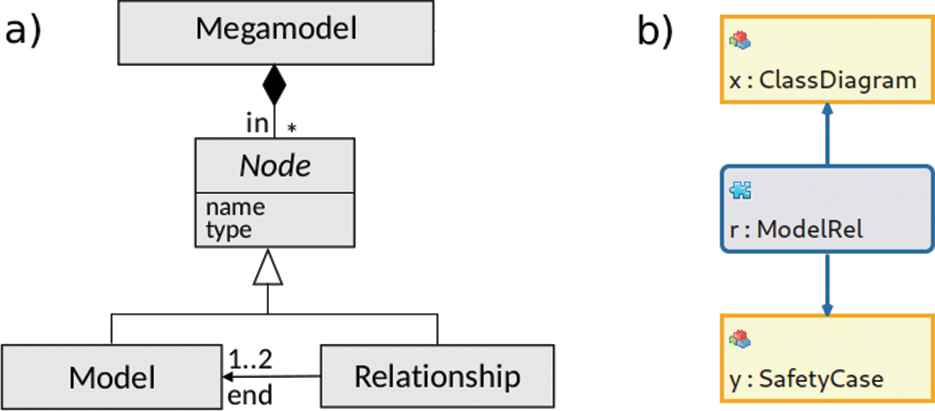
(a) Metamodel of megamodels. (b) Example megamodel.
In the example megamodel in Figure 2(b), the relationship r connects the class diagram model x and the safety case model y. This figure also introduces our notation: models are yellow boxes and relationships are blue/gray rounded boxes with blue arrows connecting the model endpoints. Both kinds of boxes contain the name of the artifact (e.g., r, x, y) and its type (e.g., ModelRel, ClassDiagram, SafetyCase).
3.2. MMINT
MMINT [16] is an interactive framework for model management.2 Implemented in Java, it extends the MMTF model management framework [20]. MMINT uses the Eclipse Modeling Framework (EMF) [21] as modeling technology and the Eclipse Graphical Modeling Framework (GMF) to create custom editors for editing models and relationships. The overall architecture of MMINT is illustrated in Figure 3.

Architecture of Model Management INTeractive (MMINT).
In MMINT, a megamodel is referred to as a Model Interconnection Diagram (MID) and is managed through the MID editor. Engineers can use the MID editor to interactively create models and relationships, invoke transformations on them and inspect the results in a graphical way. Customizations and supporting tools such as type-specific editors, validation checkers, solvers and transformations, can be plugged in and are managed by the type support run-time layer. In addition, MMINT provides a generic relationship editor which allows creating and editing sets of links between model elements.
3.3. Safety Cases and ASILs
Safety cases are structured arguments intended to assure that systems adequately mitigate identified hazards. Safety cases are frequently represented in the GSN [22] modeling language. GSN is comprised of six core elements—see Figure 4. Safety arguments in GSN are typically organized into a tree of these core element types: goal (box), strategy (parallelogram) and solution (circle). The overall goal to be satisfied by the system is the root element being gradually decomposed (possibly via strategies) into sub-goals and, finally, into solutions, which are the leaves of the safety case representing the types of evidence obtained from analyzing the system.
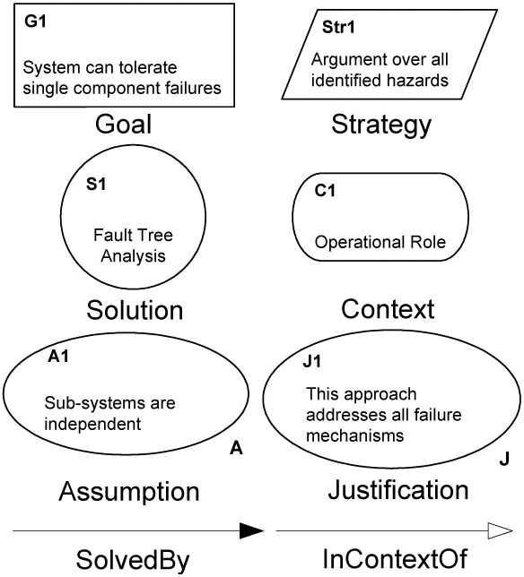
Core Goal Structured Notation (GSN) elements from Ref. [22].
Connections between goals, strategies and solutions are represented by solved-by relations which indicate inferential or evidential relationships between elements. Goals and strategies may be optionally associated with some contexts, assumptions and/or justifications by means of in-context-of relations. These declare a contextual relationship between the connected elements. We extend GSN with an additional notation (small square boxes on the bottom right of the goals) used to reflect the ASIL of the goal. The ASIL is a risk classification scheme defined in the ISO 26262 standard. Associated with a goal, ASIL values can be QM, A, B, C or D, ordered from the lowest to the highest risk.
For example, consider the safety case in Figure 5. The top level goal is “G0: The LMS system safety goals are satisfied.” This is decomposed into sub-goals G1 - G3 via a strategy “S0: Coverage over all safety goals” which means that all sub-goals need to hold in order for the parent goal to hold. Safety goals G2 and G3 are derived from hazards identified by a hazard analysis step, and are assigned ASIL levels A and B, respectively. They are each linked to a contextual element, C0 and C1, respectively, which refer to the hazard that each safety goal is derived from. Goal G1 is linked via a strategy S20 to a supporting solution “Sn0: HAZOP reviewed by expert” which points to the HAZOP documentation, which has been reviewed by an expert, as supporting evidence. The two other safety goals are decomposed further all the way down to leaf level goals that are eventually supported by evidence through solution nodes in the safety case. The decomposition takes into account ASIL propagation and decomposition rules as stated in the ISO 26262 standard. LMS describes a LMS from the automotive domain. It is considered to be an Advanced Driver Assistance System (ADAS) system, which is safety critical and subject to the ISO 26262 standard.
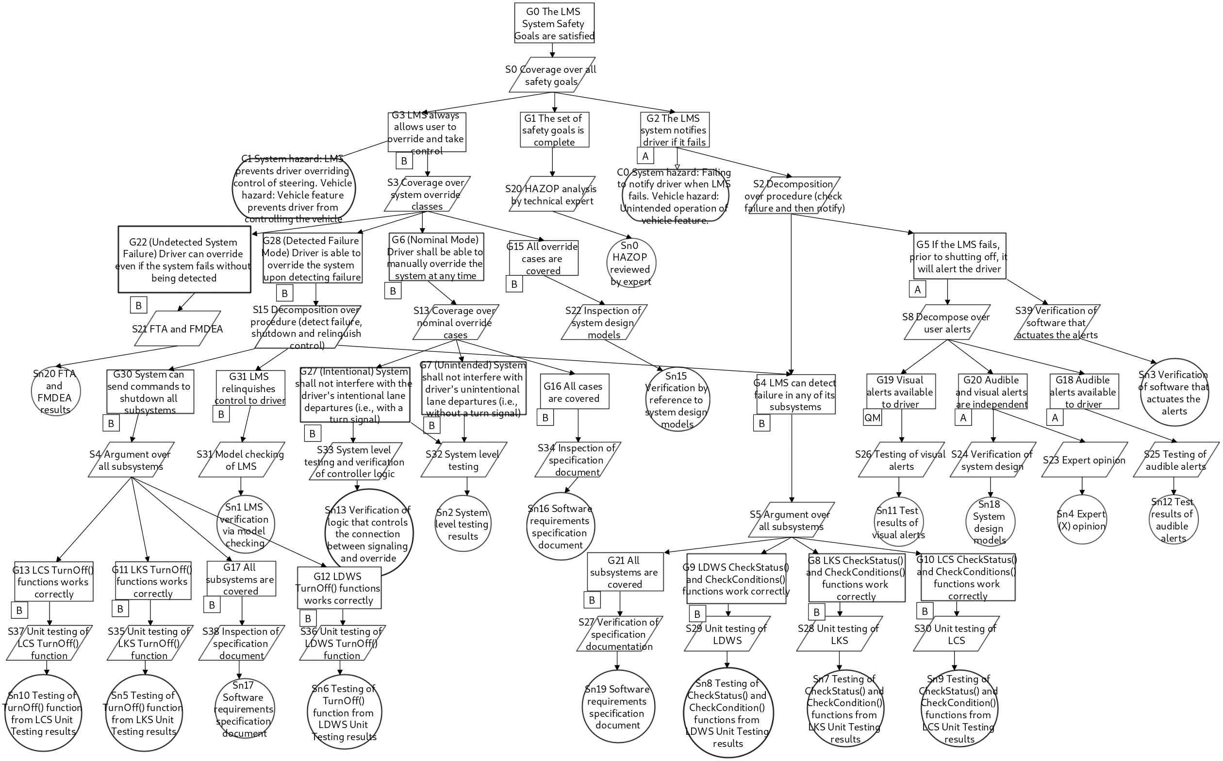
Lane Management System (LMS) Safety Case in Model Management INTeractive (MMINT).
The Software Requirements Specification (SRS) document for LMS from Ref. [24] describes LMS as consisting of several subcomponents. These subcomponents include a Lane Centering System (LCS), a Lane Departure Warning System (LDWS) and a Lane Keeping System (LKS). LMS is designed to be placed in automobiles as a safety feature with the goal of keeping the driver's vehicle in or near the center of their lane to avoid crashes caused by drivers who become distracted and therefore inattentive to what lane they are in. The LDWS will issue warnings to the driver when the system determines that a lane change was unintentional. The LCS and LKS will work together to take control of the vehicle and adjust to a driver-defined center of the lane. The overall system will make use of output data from several already-developed subsystems including Camera Sensing Subsystem, Image Processing Subsystem, Vehicle State Estimation System, Path Prediction Subsystem, Driver Interface Subsystem and a Supervisory Control System. LMS will be able to take control of the vehicle's braking and steering systems; however, the system will not be able to accelerate. Finally, the LMS will work at speeds above five miles per hour only.
LMS is comprised of one class diagram, four sequence diagrams and four state machines (i.e., a total of nine system design models), which are described in Ref. [24]. The corresponding megamodel of LMS in MMINT is shown in Figure 6. For example, Figure 7 shows the class diagram for LMS. This class diagram depicts the various subcomponents of LMS, in terms of classes with their attributes and operations, and associations between them.
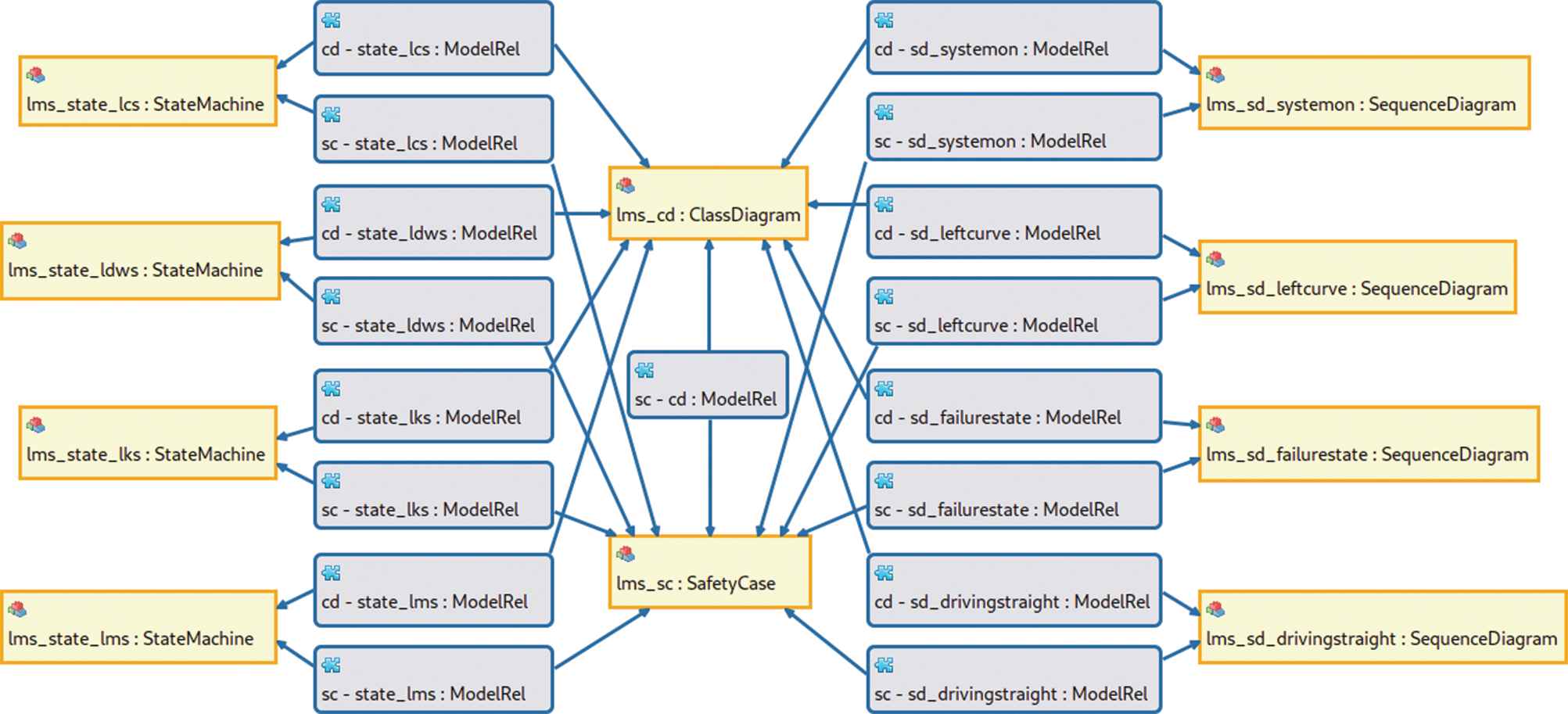
System megamodel for the Lane Management System case study [23].
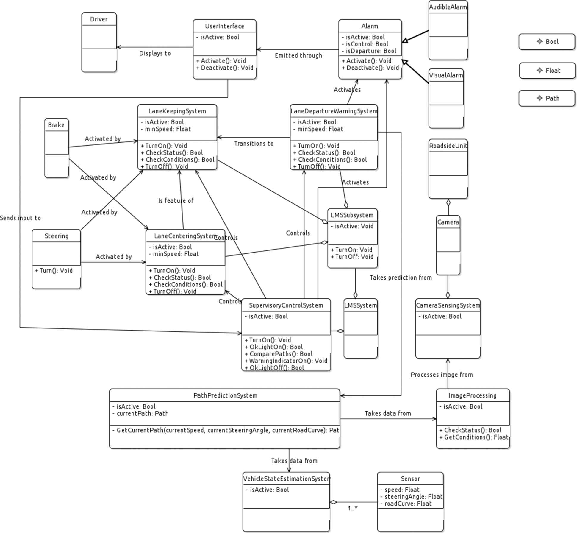
Lane Management System (LMS) class diagram in Model Management INTeractive (MMINT).
The complete set of system models that are part of LMS, together with the list of traceability links between models, can be found in Ref. [23].
3.4. Building the LMS Safety Case
We now derive a safety case for LMS. We describe the process, instantiate it for LMS, and identify cases where querying can aid this construction.
Hazard analysis and ASIL derivation. The first step in creating a safety case is identifying the system hazards by means of a hazard analysis activity. A hazard, as defined in ISO 26262, is a potential source of harm (physical injury or damage to the health of persons) caused by malfunctioning behavior (failure or unintended behavior of an item with respect to its design intent) of the item (in this case, the LMS system under consideration).
As described in ISO 26262, a HARA method is used to identify and categorize hazardous events of items, and to specify safety goals and ASILs related to the prevention or mitigation of the associated hazards in order to avoid unreasonable risk. For this, the item is evaluated w.r.t. its functional behavior; therefore, the detailed design of the item does not necessarily need to be known. Safety goals and their assigned ASILs are determined by a systematic evaluation of hazardous events. The ASIL is determined by considering the estimate of the impact factors, i.e., severity, probability of exposure and controllability. The severity represents an estimate of the potential harm in a particular driving situation, while the probability of exposure is determined by the corresponding situation. The controllability rates how easy it is for the driver or other road traffic participant to avoid the considered accident type in the considered operational situation.
Conducting a high-level hazard analysis for LMS yields the following two hazards:
System Hazard 1 (H1): Failing to notify driver when LMS fails (Vehicle Hazard: unintended operation of vehicle feature).
System Hazard 2 (H2): LMS prevents driver overriding control of steering (Vehicle Hazard: vehicle feature prevents driver from controlling the vehicle).
In order to determine the appropriate ASIL level assigned to each of the hazards, we assign levels for each of their severity, probability of exposure and controllability. Based on the guidance in the standard and expert opinion from our industrial partner, we have assigned the two hazards the levels shown in Table 1. We then used the ASIL determination given by the standard and shown in Table 2, to compute the associated ASILs; ASIL A for H1 and ASIL B for H2.
| ID | Severity | Exposure | Controll. | ASIL |
|---|---|---|---|---|
| H1 | S1 | E4 | C2 | A |
| H2 | S3 | E2 | C3 | B |
LMS, Lane Management System; ASIL, Automotive Safety Integrity Level.
LMS hazard analysis.
| Severity | Exposure | Controllability |
||
|---|---|---|---|---|
| C1 | C2 | C3 | ||
| S1 | E1 | QM | QM | QM |
| E2 | QM | QM | QM | |
| E3 | QM | QM | A | |
| E4 | QM | A | B | |
| S2 | E1 | QM | QM | QM |
| E2 | QM | QM | A | |
| E3 | QM | A | B | |
| E4 | A | B | C | |
| S3 | E1 | QM | QM | A |
| E2 | QM | A | B | |
| E3 | A | B | C | |
| E4 | B | C | D | |
ASIL) determination table from Ref. [1].
Extracting information from ISO 26262 could be done via querying, e.g., finding the correct ASILs from the ASIL determination Table 2. It requires encoding parts of the standard as models [2,3,25].
Representing a safety case. Next, we constructed a GSN representation of a safety case for LMS, which is shown in Figure 5. We started by defining a top level goal “G0: The LMS System Safety Goals are satisfied”. G0 is decomposed into
“G1: The set of safety goals is complete,” which is a claim about the completeness of the system safety goals,
“G2: The LMS system notifies driver if it fails,” which is a safety goal associated with hazard H1 (see the context node C0), and assigned an ASIL A, and
“G3: LMS always allows user to override and take control,” which is a safety goal associated with hazard H2 (see the context node C1), and assigned an ASIL B.
ASIL decomposition rules from ISO 26262 are listed in Table 3. Similarly to the initial ASIL determination from the previous stage, queries can help select the appropriate decomposition rules from the standard. G2 is then decomposed into
“G4: LMS can detect failure in any of its subsystems” and
“G5: If the LMS fails, prior to shutting off it will alert the driver.”
| Original ASIL | Decomposed ASILs | ||
|---|---|---|---|
| D | C + A | B + B | D + QM |
| C | B + A | – | C + QM |
| B | A + A | – | B + QM |
| A | – | – | A + QM |
ASIL) decomposition strategies from Ref. [1].
Note that while G5 inherits the ASIL of its parent's goal (A), G4 is assigned a higher ASIL (B) as it also supports goal G28 which has ASIL B.
The safety case construction involves the decomposition of high-level claims into subclaims. Queries can be used to aid in this process by finding the potential subjects for subclaims. The use of a query helps ensure that the set of subclaims is complete—an important property of a sound decomposition. For example, the decomposition of G5 is particularly interesting, using the strategy “S8: Decompose over user alerts.” In this case, the safety engineer can benefit from querying the system design models to identify the different user alerts that exist in the system, and ensure that the goal G5 is completely decomposed over them. This corresponds to Scenario 1 of Section 2 and is implemented in Section 5.1.
We continued the goal decomposition until we reached a set of leaf goals that can no longer be decomposed, but can be directly linked to supporting evidence via solution nodes. More details about this process can be found in Ref. [23].
Adding traceability links. In this final step, we created links connecting the LMS system design models to the safety case. We can leverage queries at this step as well, and a simple strategy is to select one or more keywords from each goal to find system elements by name. For example, let us consider the goals G11, G12 and G13, which refer to the three subcomponents of LMS and share a similar text “LKS/LDWS/LCS TurnOff() function works correctly.” A query can be used to find the appropriate TurnOff() function within a specific subcomponent in order to create the three traceability links. This is Scenario 2 of Section 2, implemented in Section 5.2.
Table 4 lists the traceability links from the LMS safety case elements in Figure 5 to the LMS class diagram elements in Figure 7. We are aware that this table is not complete, i.e., there could be other links from the safety case to the system models; our goal here is just to demonstrate the approach. More complicated strategies and queries, such as the ones described in Refs. [26–29], can also be used to create traceability links.
| Safety Case | Class Diagram |
|---|---|
| Goals G0, G2, G3, G4, G5, G6, G22, G28, G31 | Class LMSSystem |
| Goals G18, G20 Solutions Sn3, Sn12 | Class AudibleAlarm |
| Goals G19, G20 Solutions Sn3, Sn11 | Class VisualAlarm |
| Goal G8 Solution Sn7 | Operations LKS.CheckStatus, LKS.CheckConditions |
| Goal G9 Solution Sn8 | Operations LDWS.CheckStatus, LDWS.CheckConditions |
| Goal G10 Solution Sn9 | Operations LCS.CheckStatus, LCS.CheckConditions |
| Goal G11 Solution Sn5 | Operation LKS.TurnOff |
| Goal G12 Solution Sn6 | Operation LDWS.TurnOff |
| Goal G13 Solution Sn10 | Operation LCS.TurnOff |
LMS, Lane Management System; LCS, Lane Centering System; LDWS, Lane Departure Warning System; LKS, Lane Keeping System.
LMS safety case to LMS class diagram traceability.
3.5. LMS Evolution
After being created, the LMS megamodel is used and modified by system and safety engineers. In this “Evolution” phase, queries are essential since they can be used to understand the potential effects of proposed changes. For example, the engineers may consider a change to the ASIL of goal G5 in the safety case. They can ask which other system elements are connected through traceability links to determine the impact of this change on the rest of the system and identify which other stakeholders need to be involved in the decision making. The opposite direction can also be explored, targeting a change to one of the system models, e.g., the class LMSSystem, and asking which safety case elements are potentially impacted and which can be reused [30].
The use of traceability links at this stage is fundamental, as they enable queries that span the entire megamodel. The relevant queries for these tasks represent Scenarios 3 and 4 in Section 2 and are discussed in Sections 5.3 and 5.4, respectively.
4. QUERYING MEGAMODELS
In this section, we define a set of requirements that a query engine built on top of megamodels should implement, split into generic and implementation-specific. We then discuss and compare two query language candidates, the OCL and the Viatra Query Language (VQL). We conclude with description of our implementation.
4.1. Query Engine Requirements
A megamodel grows in size more than linearly in the number of models it contains, due to the number of relationships that can be created. Each relationship in turn stores links between individual model elements. The upper bound is to have a complete graph, with each model connected to every other model. The automotive domain tends to be densely interconnected, with the safety artifacts connected to most domain models. For example, in Figure 6, both the class diagram model and the safety case model have relationships with every other domain model. Visually browsing a megamodel to find the required information becomes impractical after the megamodel reaches a certain size. We can draw an analogy with databases, as they both contain heavily structured data which is directly addressable for more effective processing and analysis. A query language on top of the megamodel data becomes necessary to address the complexity of gathering information.
A query engine for megamodels has to navigate instances of the metamodel in Figure 2. This means being able to follow relationships from a model to a model, as well as accessing heterogeneous models (i.e., of different types) and navigating their internal structure. Thus, in Table 5 we define a set of requirements for the query engine, split into generic requirements that apply to any engine, and implementation-specific requirements that are tied to the Eclipse platform on which MMINT is based.
| ID | Requirements |
|---|---|
| Generic | |
| 1 | Support a two-tiered navigation: inter-model and intra-model. |
| 2 | Handle heterogeneous models in the same query. |
| 3 | Allow obtaining a particular result from a query, or the set of all results from a query; e.g., given a query |
| 4 | Provide mechanisms to select query inputs and display results in a megamodel. |
| 5 | Scale to handle big models. |
| Implementation-specific | |
| 6 | Integration with eclipse modeling framework (EMF). |
| 7 | Availability of APIs to programmatically load and invoke queries. |
Query engine requirements.
4.2. Object Constraint Language
OCL is an Object Management Group standard for describing rules and expressions on UML models.3 The Eclipse project provides an implementation of the OCL standard for EMF models [31], and uses it as the default language for constraints and queries. In the rest of the paper, we use the term “OCL” to refer to the Eclipse implementation of OCL.
Figure 8 shows an example of the OCL syntax. An OCL file has the .ocl extension and declares a set of contexts where statements are valid, i.e., which model elements the keyword self-corresponds to. Operations are defined with the def keyword, a name, a list of parameter variables, and the type of output, similar to a programming language. The implementation is a single statement that follows the = character, using a functional programming paradigm. The OCL standard library provides a long list of operations that can be used to implement queries, including existential and universal quantification (exists, forAll), filter (select, reject), map (collect), reduce (iterate), aggregators (count, sum, min, max) and the transitive closure operator (closure). Variables can be compared for equality (=) and inequality (<>), and new variables can be introduced with the let keyword.
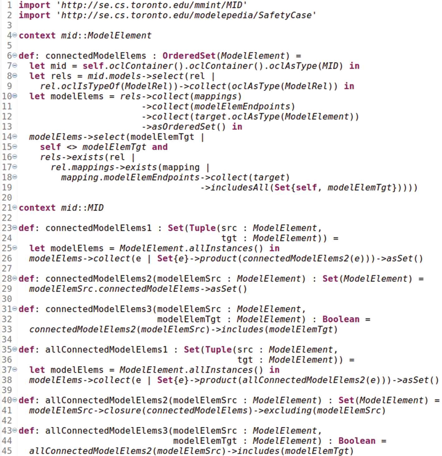
An Object Constraint Language (OCL) query file.
To execute a query, the OCL engine is initialized with a model context. Then, it runs the operation with the passed parameters and returns the results.
4.3. Viatra Query Language
Viatra is an Eclipse-based framework for the development of event-driven, reactive model transformations [14]. It includes an incremental query engine and a graph pattern-based language to specify and execute model queries efficiently, based on the Rete algorithm [32].
Figure 9 shows an example of the VQL syntax. A VQL file has the .vql extension and defines a namespace with the package keyword. Model patterns are defined with the pattern keyword, a pattern name and a list of parameter variables. Then, enclosed in curly braces, a list of constraints defines the conditions for the pattern to match. The available constraints include equality (==) and inequality of variables (!=), type declarations and model traversal (highlighted in blue in Figure 9), pattern composition (find), aggregators (count, sum, min, max), transitive closure of a binary pattern (+). Constraints can introduce additional variables for intermediate use, or have single-use anonymous variables (_).
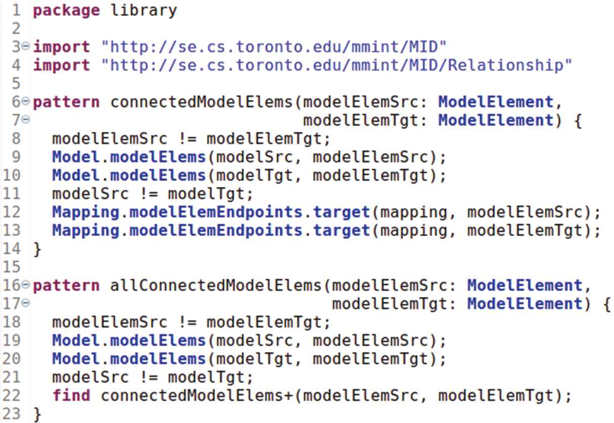
A VQL query file (part of the MID.vql library).
When a query pattern is being matched, the Viatra query engine finds model objects that satisfy the list of constraints and binds them to the pattern variables: given a model or a set of models as inputs, the query engine returns a set of all the available matches. Any of the pattern arguments can be manually bound to restrict the set of matches. An unbound argument is automatically searched by the Viatra query engine from the set of available model elements.
4.4. Comparison of OCL and VQL
We compared OCL and VQL against the query engine requirements, showing the outcome in Table 6. Both engines satisfy Requirements 1, 2, 4—they can navigate arbitrary model structures, mix multiple models in the same query and allow easy selection of inputs and display of outputs.
| Req. ID | OCL | VQL |
|---|---|---|
| Generic | ||
| 1 | ✓ | ✓ |
| 2 | ✓ | ✓ |
| 3 | ✓ (Separate queries) | ✓ |
| 4 | ✓ | ✓ |
| 5 | ✗ | ✓ |
| Implementation-specific | ||
| 6 | ✓ | ✓ |
| 7 | ✓ | ✓ |
OCL, Object Constraint Language; VQL, Viatra Query Language.
Comparison of query engine requirements for OCL and VQL.
OCL partially satisfies Requirement 3, while VQL fully satisfies it. VQL has a higher evel syntax than OCL—model traversal is simpler, and queries can be more concise due to the support for bound and unbound arguments within one query, so that a single VQL query can be used both to get a particular result, and for all results. OCL does not support unbound arguments, requiring multiple separate queries to achieve the same flexibility. For example, Figures 8 and 9 show the same queries implemented using OCL and VQL. The OCL implementation spans 45 lines of code, while the VQL implementation is only 23. Each of the two VQL queries requires three separate OCL queries to achieve equivalent results, impacting the size and readability of the OCL code, e.g., the query connectedModelElems in Figure 9 is implemented with queries connectedModelElems1, connectedModelElems2 and connectedModelElems3 in Figure 8.
For Requirement 5, VQL scales an order of magnitude better than OCL, based on the evaluation reported in Refs. [33–35]. Query execution time in VQL is constant with respect to the model size, while it is polynomial in OCL. VQL is optimized for large models, using the Rete algorithm to populate an in-memory index of model elements, which is then kept up-to-date on subsequent model changes. VQL queries the in-memory index in constant time, while OCL traverses the models for each query. We thus deem this requirement unsatisfied for OCL.
Finally, both engines satisfy Requirements 6, 7. They are integrated with Eclipse EMF and provide APIs for loading and invoking queries.
Based on this comparison, we believe that VQL is a superior choice in terms of performance, flexibility for writing queries, readability and maintainability of query code in the long term, and thus choose to implement megamodel queries in MMINT using Viatra.
4.5. Viatra Integration in MMINT
The main goal of our Viatra integration in MMINT is to be able to run queries directly from the MID editor in a graphical way. Viatra has its own separate graphical interface to run queries, but provides a set of APIs to plug the query engine into other projects. In this section, we discuss the details of the integration work.
4.5.1. Query abstraction layer
In order to accept query inputs and present outputs graphically, we add a Query Abstraction Layer (QAL) in MMINT. The QAL defines a programming interface to plug in query engines and integrates them with the MID editor. Query inputs are selected graphically by clicking on megamodel elements. They are bundled with the specified query and dispatched to the query engine. The query results are returned as EMF objects, allowing us to find and highlight the corresponding megamodel elements—we are currently working on implementing this functionality and evaluating a number of UI prototypes. Finally, we create a Viatra connector that implements the QAL interface.
The QAL interface allows plugging in arbitrary query languages, as long as an appropriate connector that implements it is created. For example, Figure 10 shows the QAL interface method to run a query, written in Java. It requires (a) the path to the query file, (b) the query name, (c) the context of execution and (d) the query arguments, and returns a list of objects that match the query. The Viatra connector implements this interface by invoking specific Viatra APIs to (a) load a VQL file, (b) find a VQL pattern with the specified name, (c) initialize the execution context and (d) bind the pattern arguments, and it returns the objects matching the pattern.
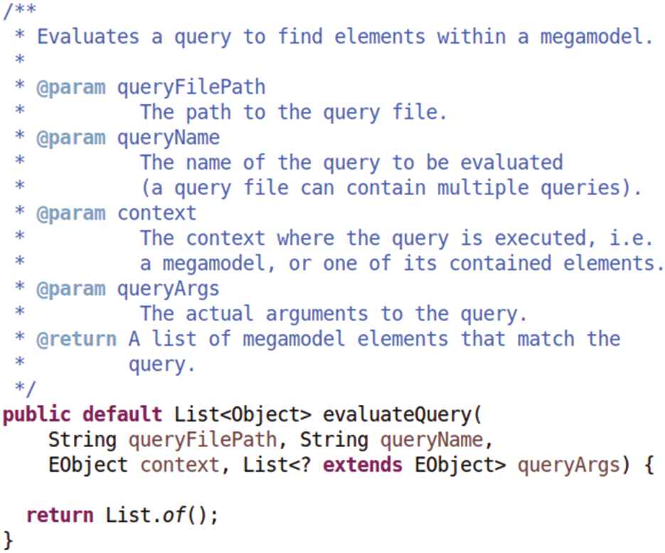
The Query Abstraction Layer (QAL) Java interface to run a query.
4.5.2. MID VQL library
After writing a few queries, we noted that navigating a megamodel is repetitive, since there are frequently used patterns that lead to code duplication. We have thus started the process of building a library of queries, extracting these patterns for reuse into a separate MID.vql library, a portion of which is depicted in Figure 9. A megamodel query library is particularly useful because it lets users focus on queries that are within their domain expertise, e.g., the automotive domain, since they don't need to know the details of megamodel navigation.
For example, queries connectedModelElems and allConnectedModelElems are part of the library—the former finds model elements that are directly connected through model relationships, while the latter finds model elements that are directly and indirectly connected via multiple hops. Both queries are defined in the library namespace and contain only code that refers to megamodel navigation, i.e., accessing elements from the MID metamodel in MMINT. Users can directly use queries in the library, or build upon it to create more complex queries. Figure 11 shows examples of invoking a library query on lines 22 and 28: the connectedModelElems query is prefixed with the library namespace, and invoked with the find keyword. Note that the remaining query code focuses exclusively on model-specific content and does not contain any other megamodel navigation procedure. The advantages of using the MID.vql library are clear—we take care of providing and maintaining primitives to navigate megamodels which can be used for creating domain-specific queries. The resulting queries are smaller, easier to maintain and megamodel independent.
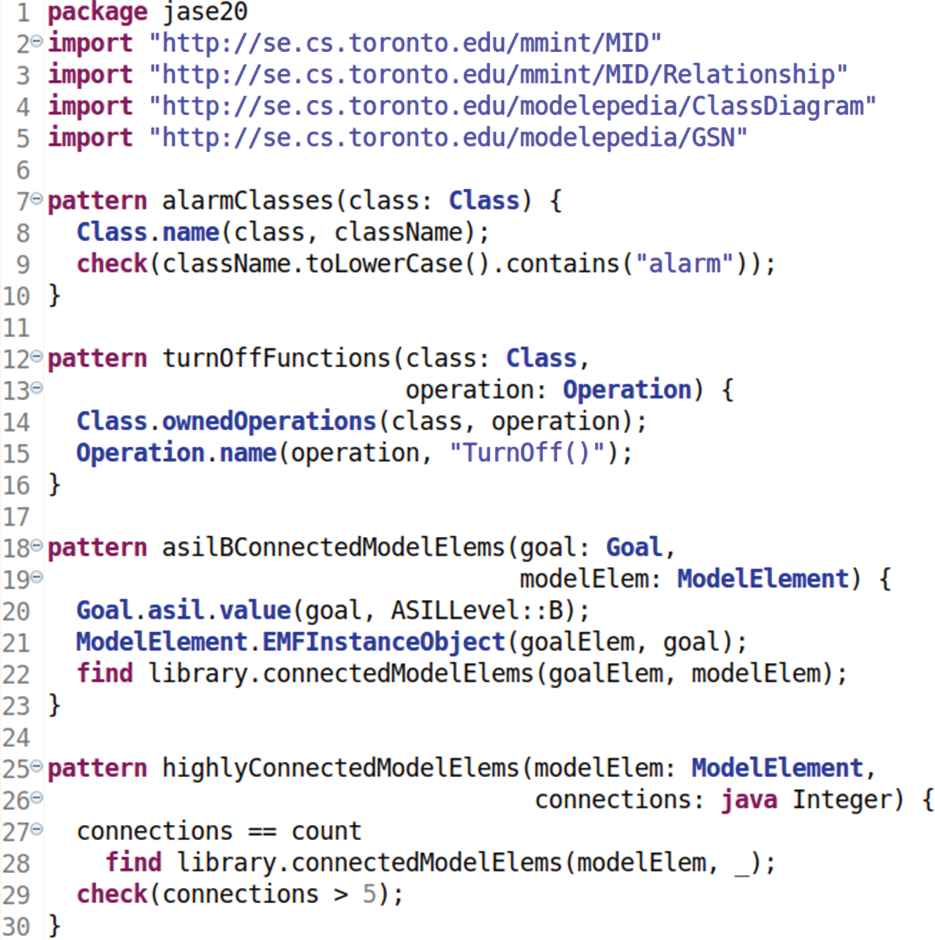
The Viatra Query Language (VQL) queries used in the example scenarios.
We aim to expand this library as we find more common megamodel queries in the future and demonstrate one such addition in Section 6. We are including the library into our MMINT installation package.
5. QUERYING THE LMS SYSTEM
In this section, we illustrate querying in MMINT using the LMS case study (see Figure 6) and the six scenarios described in Section 2. Scenarios 1 and 2 are simple model queries that do not require any megamodel navigation. Scenarios 3 and 4 directly use queries from the MID.vql library, while Scenarios 5 and 6 require more complex queries that in turn invoke the library queries. For all scenarios, the instructions to run queries in the tool are as follows:
Open the LMS megamodel.
(optional) Open one of the LMS models and select one or more model elements if we are binding query arguments.
Use the MMINT context menu to invoke a query, selecting the query file and the query name.
View the query results.
5.1. Scenario 1: Building the Safety Case
This scenario takes place during the construction of the safety case, before it is finalized. The safety engineers of the automotive company can query the system design models early on to help with the decomposition of safety goals. For example, assume that they are in the process of decomposing goal “G5: If the LMS fails, prior to shutting off, it will alert the driver” in the LMS safety case from Figure 5. They would like to identify the different user alarms that exist in the system in order to decompose the goal completely over them. They can use the query alarmClasses shown in Figure 11, getting as results the abstract class Alarm, concrete classes AudibleAlarm, VisualAlarm from the class diagram in Figure 7. The goal G5 can then be decomposed accordingly, into “G18: Audible alerts available to driver,” “G19: Visual alerts available to driver” and “G20: Audible and visual alerts are independent.”
5.2. Scenario 2: Adding Traceability Links
This scenario can take place during or immediately after construction of the safety case, with the safety and system engineers working together to keep track of the system design model elements that are relevant to the safety elements, through the use of traceability links. For example, suppose they are reviewing the goals G11, G12 and G13 which share a similar goal “LKS/LDWS/LCS TurnOff() function works correctly” and refer to the three subcomponents LKS, LDWS and LCS. They can use the query turnOffFunctions shown in Figure 11 and get the three classes LaneKeepingSystem, LaneDepartureWarningSystem, LaneCenteringSystem as results from the class diagram in Figure 7 and their respective TurnOff() functions. This process ends with the creation of three traceability links connecting goal G11 with operation LKS.TurnOff(), G12 with LDWS.TurnOff() and G13 with LCS.TurnOff().
5.3. Scenario 3: Safety Case Change
In this scenario, the safety engineers of the automotive company are now reviewing the ASIL of goal G5. To evaluate the effects of an ASIL change, they would like to know which model elements from the various system models are directly connected to the safety goal. From the MID.vql library in Figure 9, the query connectedModelElems is used for this scenario. We select the goal G5 before invoking the query, in order to bind it to the first query argument modelElemSrc, as shown in Figure 12. We get a single query result, the class LMSSystem from the class diagram in Figure 6.
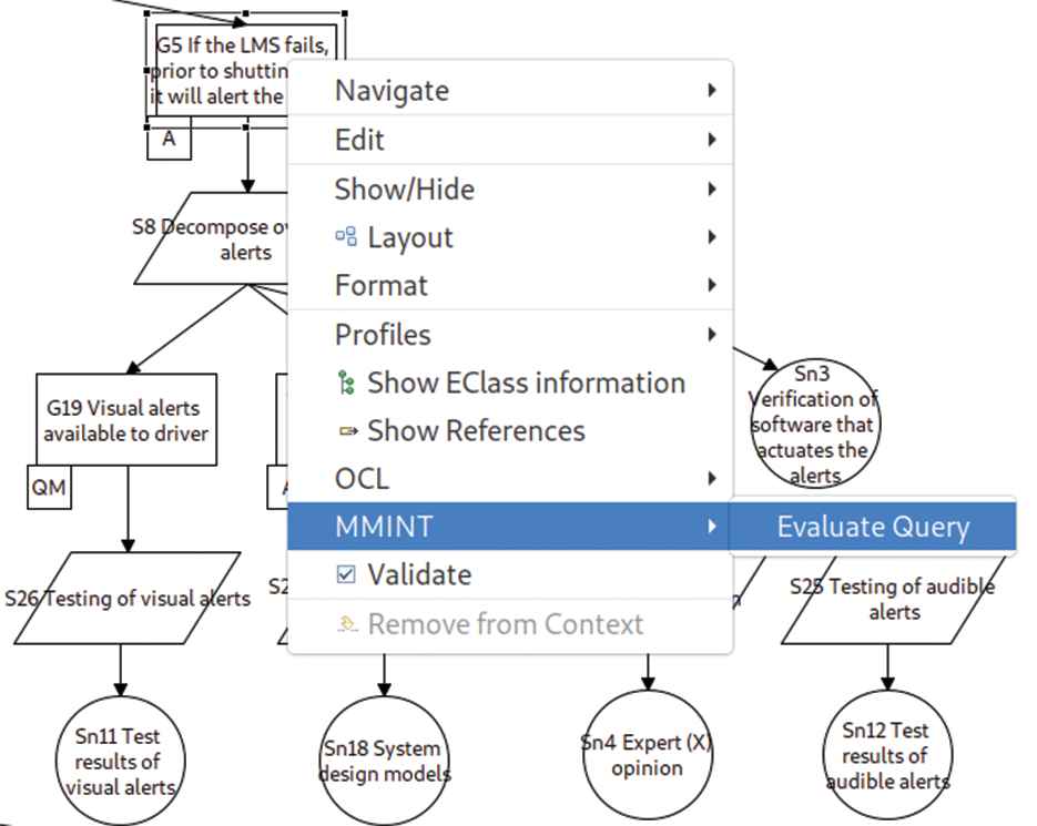
The Model Management INTeractive (MMINT) menu to evaluate a query from a bound argument.
The variant query named allConnectedModelElems can alternatively be used for this scenario, to find all model elements that are directly and indirectly connected to goal G5 through any number of hops (through the LMS class diagram in this example). This query uses the transitive closure feature of Viatra, yielding the class LMSSystem from the class diagram and four other model elements from the state machine system models.
5.4. Scenario 4: System Model Change
In this scenario, the system engineers of the automotive company are modifying the system models and looking for the potential impact to the safety model. This is in contrast with Scenario 3, where the safety engineers were modifying the safety model and looking at the impact to the system models instead. Specifically, the system engineers are targeting a change to the class LMSSystem in the LMS class diagram from Figure 7. We can reuse the query connectedModelElems from the previous scenario, since it works in the opposite direction as well, this time binding the first argument modelElemSrc of the query to the class LMSSystem. The query results are the goals G0, G2, G3, G4, G5, G6, G22, G28, G31 from the safety case in Figure 5 (consistently with the traceability Table 4), and four other model elements from the state machine system models.
5.5. Scenario 5: Identifying Medium Risk Elements
The objective of this scenario is to identify all model elements connected to any safety goal with an ASIL B. This scenario is a concrete example of the dual inter-model and intra-model navigation requirement 1 introduced in Section 4.1, and is implemented with the query asilBConnectedModelElems in Figure 11. Firstly, the query finds safety goals with the ASIL B feature within the safety case model. Secondly, we switch to the megamodel level to follow relationships involving those goals. We find connected model elements in other models by invoking the connectedModelElems library query used for the previous scenarios. This query runs with all arguments unbound on the main LMS megamodel, finding all the results, i.e., a list of fifteen pairs of goals from the safety case and classes from the class diagram as results, corresponding to the subset of Table 4 with ASIL B. In alternative, it can run on the safety case model after selecting a single goal, which is bound to the first argument goal. For example, running it on goal G5 would yield an empty result, because it has ASIL A. This scenario highlights how the same query can be used to get all results, or a particular result.
5.6. Scenario 6: Identifying Highly Interconnected Elements
The goal of this scenario is to find all model elements that are highly interconnected within the LMS megamodel. As an example, the automotive engineers may consider an element to be highly interconnected when it has more than five connections to other elements in the system. In Figure 11, we use the query
5.7. Comparing OCL and VQL Scenario Queries
In Section 4.4, we compared OCL and VQL against our query requirements and selected VQL. We now aim to compare the two languages on the specific example queries developed for the above scenarios. We have created an additional OCL connector implementing the QAL interface described in Section 4.5.1, and used it to implement the example scenarios in OCL. We then analyzed the syntax of the queries and measured their execution times. For simplicity, we show the OCL implementation of the queries for Scenarios 3 and 4 only in Figure 8.
Query size and complexity. From a qualitative perspective, queries in OCL are longer and more complex to write than VQL, because of the lower level model traversal. The reason can be found in the query arguments: VQL allows both unbound and bound arguments in one query definition, while OCL only supports bound arguments, as discussed in Section 4.4 for generic requirement 3. In OCL, the user must explicitly implement the equivalent of the VQL unbound search, which can be hard to optimize and leads to an increase in query complexity. Figures 8 and 9 show the same queries, with OCL requiring three queries to implement each VQL query.
Running times. Table 7 shows the running times of VQL and OCL queries for each scenario. VQL times are roughly constant and under 1 second, while OCL times grow with the increasing complexity of the examples, which matches the observations from Refs. [33–35] (see Section 4.4, discussion on generic requirement 5). While the unbound search in Viatra is very efficient and is indexed by the engine, our functionally equivalent OCL implementation is slow.
| Scenario | VQL Time (s) | OCL Time (s) |
|---|---|---|
| 1 | 0.635 | 0.326 |
| 2 | 0.569 | 0.310 |
| 3 | 0.686 | 0.411 |
| 4 | 0.761 | 0.436 |
| 5 | 0.830 | 2.220 |
| 6 | 0.599 | 32.996 |
OCL, Object Constraint Language; VQL, Viatra Query Language.
Comparison of query execution times for each example scenario.
Summary. The experience of running our query engine for the LMS example confirms the conclusion from Section 4.4—VQL is a higher level language that is easier to use and has a faster query execution engine. A threat to validity in this analysis is our limited expertise with writing both VQL and OCL queries and the fact that we only applied them to specific scenarios.
6. USING QUERIES FOR ISO 26262 COMPLIANCE
In this section, we aim to validate the applicability of our approach by using queries to achieve a complete coverage of a fragment of the ISO 26262 standard. We choose the process detailed in Part 3 “Concept phase,” Clause 7 “HARA,” which is further divided into five main steps. The final step §7.4.5, titled “Verification,” has the goal of verifying the correctness and completeness of the HARA from the preceding four steps. This verification step consists of a single sub-clause §7.4.5.1, quoted in the left-hand side of Figure 13.
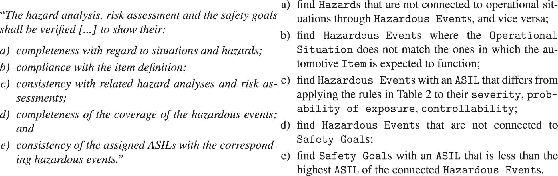
The complete sub-clause §7.4.5.1, quoted from the ISO 26262 standard (left), and the corresponding natural language queries (right).
6.1. Relevant Metamodels
In order to create meaningful queries to cover this fragment of the standard, we must first identify the relevant metamodels and the relationships between them, shown in Figure 14. Dashed areas represent separate metamodels, boxes are elements of such metamodels, and lines show metamodel relationships with their cardinality. When instantiated, e.g., one Item in a SysML model is connected to one or more Operational Situations in a HARA model. We omit the full structure of the metamodels for simplicity.

The relevant metamodels for the sub-clause §7.4.5.1 of the ISO 26262 standard in Figure 13.
An automotive Item has a set of Operational Situations in which it is expected to function in a safe manner. The same Item, if malfunctioning, can cause Hazards. Hazardous Events are relevant combinations of Operational Situations and Hazards. Each Hazardous Event is assigned a severity, probability of exposure, controllability, and an ASIL that is calculated based on them (see Section 3.4 for a detailed explanation). A Safety Goal is determined for each Hazardous Event, with a corresponding ASIL. Multiple Hazardous Events can be covered by the same Safety Goal, which is assigned the highest of their ASILs.
6.2. Compliance Queries in Natural Language
The next step is to create natural language queries that aim to find sets of models which are not in compliance with the standard. We use our knowledge of the ISO 26262 standard, the metamodels, their structure and their relationships to interpret the text of the sub-clause §7.4.5.1 in the left-hand side of Figure 13. The resulting natural language queries are shown on the right-hand side of Figure 13 and achieve full coverage of the sub-clause §7.4.5.1.
For example, consider the text of the standard for Requirement b). In terms of the life cycle of the models, an automotive Item is first created and associated with Operational Situations where it is expected to function safely. In a subsequent phase, a hazard analysis is conducted, which identifies a set of Hazards, Hazardous Events and Operational Situations for potential malfunctions. A mistake can be made during the hazard analysis by creating an Hazardous Event for an Operational Situation where the Item is not originally supposed to operate properly (e.g., a normal vehicle is not expected to travel cross-country at a high speed). This problem can be found by the corresponding natural language Query b).
6.3. Compliance Queries in VQL
We now proceed to implement the natural language queries using VQL and show the outcome in Figure 15. We only include the rules for ASIL D in Query c) for the sake of brevity. For example, Query b) is implemented by taking a Hazardous Event, navigating to Operational Situations both through its direct link and through the indirect link crossing Hazard and Item, and checking that the Operational Situations are not the same. While creating the VQL implementation, we identified a common megamodel operation connectedEMFObjects which we packaged into a corresponding MID.vql library query—see Figure 16. This library query is used when crossing each metamodel boundary and is equivalent to the connectedModelElems query used for Scenarios 3 and 4, except that it gives access to the raw Eclipse EMF model objects.
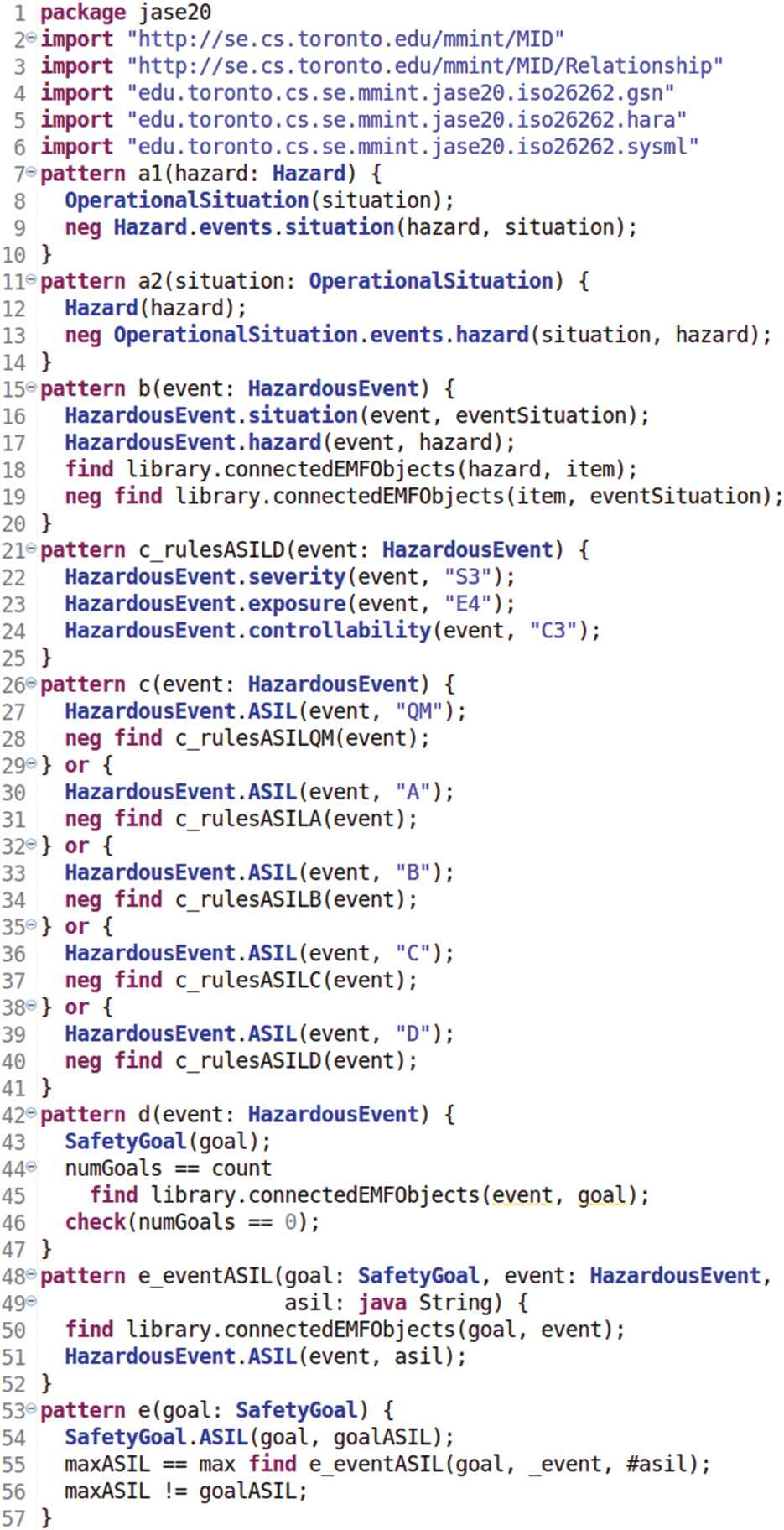
The Viatra Query Language (VQL) implementation of the queries in Figure 13.
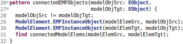
The extension to the Model Interconnection Diagram (MID).vql library in Figure 9
Verification is an important activity in the ISO 26262 standard, it must be carried out according to specific procedures contained in the standard itself, and must produce review reports. In this section we demonstrated an approach to derive compliance queries from the standard for the purpose of verification, first created using natural language and then implemented in VQL. The execution of the queries we defined allow the verification process to be completely automated. We believe that queries can help achieve compliance for other parts of the standard as well.
7. RELATED WORK
OCL has been formally developed and updated by the Object Management Group as a standalone standard since 2006, but has been available earlier as part of the UML specification. Given its maturity, OCL is implemented in a variety of modeling tools [13] and is the base language that other modeling languages are compared against.
The VQL was previously known as IncQuery [35] and has recently been merged into the Viatra framework [14]. The goal of the VQL project is to provide a fast engine based on the Rete algorithm [32] for incremental queries—queries that are evaluated frequently with moderate modifications in between, to either the queries or the queried models. Additionally, VQL queries have been used as a derived way to link model elements in heterogeneous models [36], as opposed to the structural nature of model relationships in our megamodels.
The Epsilon Object Language (EOL) [15] is OCL-based, but is designed to be metamodel independent. It can be used for model management activities such as model querying in order to project out information of interest to specific stakeholders (e.g., boolean queries to determine whether two or more models are mutually consistent, queries to select a subset of modeling elements satisfying a particular property, etc.). EOL satisfies the implementation-specific requirements in Section 4.1 and is a potential candidate for integration with MMINT.
The Hawk framework presented in Ref. [37] is a modular and scalable model indexing framework that enables developers to efficiently perform queries over large collections of models stored in version control systems. Thus, it is more geared towards distributed models and queries, whereas our approach is centralized.
The work in Ref. [38] extends the scope of model management beyond the boundaries of 3-level metamodeling architectures such as MOF and EMF, and presents an approach for querying large relational datasets using an imperative OCL-based transformation language (EOL). Our work currently only considers EMF-based models.
Other work has also considered querying large collections of models. For example, the work in Ref. [39] proposes an approach for efficient querying of large process model repositories, the survey in Ref. [40] considers approaches for efficiently querying large XML data repositories, and Ref. [41] considers the techniques and challenges in managing large collections of business processes. Both business processes and XML data repositories can be implemented as megamodels of the relevant model types in our tool MMINT, and can be queried using the approach we propose in this paper. The authors of Ref. [42] present MorsaQL, a querying approach especially designed and tailored for the Morsa repository, which is a model repository that uses a No-SQL database backend. In their work, they define four dimensions to evaluate query languages (effectiveness, usability, safety, efficiency) and compare MorsaQL with both OCL and IncQuery.
The ToolNet framework [43] tackles the problem of integrating models and artifacts from heterogeneous tools. It defines a tools layer with adapters to communicate with the various tools, a model abstraction layer to abstract the tool models away from their technical details, and an integration layer with virtual model views of the combined abstracted models. MMINT sits at the same level as ToolNet's integration layer, and uses Eclipse EMF as the model abstraction layer. In this paper, we assume that the models contained in our megamodels are either managed directly in Eclipse, or imported from external tools through transformations. Keeping the latter models synchronized with the external tools is outside the scope of this paper, i.e., we assume a deep model integration rather than a shallow one.
In Ref. [44], the authors highlight the benefits of using a model-based approach for constructing an assurance case. They use a weaving model (a simplified version of megamodel which focuses on relationships) to link the assurance case and the design models. They also demonstrate how to automatically generate the assurance case by instantiating specific GSN patterns and using queries on the weaving model.
Finally, the ANSYS Medini Analyze4 software implements key safety analysis methods, e.g., HAZOP, FTA, FMEA, failure modes, effects and diagnostic analysis (FMEDA), etc., in an Eclipse-based environment. It is well integrated with other engineering tools, and enables model-based safety analysis using standards like SysML. It also offers complete end-to-end traceability and supports the use of OCL, which could be used for querying the various artifacts through the traceability links.
8. CONCLUSION AND FUTURE WORK
In safety-critical domains such as automotive, models are used in different phases of software development (e.g., requirements, design, testing, etc.), both at the product and at the process level. Models are also used to capture safety-related information (e.g., (HARA, FTA, failure models and effects analysis (FMEA) and safety cases). This creates a large collection of heterogeneous interconnected models. Querying collections of heterogeneous models is a complex and expensive activity lacking proper tool support.
In this paper, we described the process of deriving a safety case using the LMS case study, and illustrated the use of querying to aid during its construction, as well as its evolution after the system undergoes changes. We then proposed a set of requirements for a megamodel querying system. We compared OCL and VQL against our query requirements, presented the implementation details for integrating VQL into our tool MMINT and showed its use on the LMS case study using six scenarios. We showed that VQL is a higher level language that is easier to use and has a faster query execution engine than OCL. Finally, we demonstrated the use of queries to check model compliance w.r.t. a fragment of the ISO 26262 standard.
Our work has a number of limitations:
Correctness and Completeness: The correctness of the presented queries can be reduced to the correctness of the underlying VQL language [14]. We do not make any claims about the completeness of the queries presented for the automotive domain or ISO 26262.
Applicability and Usefulness: We have shown the applicability of our model querying approach in the automotive domain and demonstrated its application on questions from the ISO26262 standard. We believe this is a useful activity for practitioners (particularly software safety engineers) but we have not yet conducted a usability study.
In the future, we plan to experiment with more scenarios on top of LMS to try different queries of different complexity levels. To do so, we plan to expand the LMS megamodel with more safety-related artifacts (e.g., hazard analysis, FTA, test results, etc.) and write queries on top of them. This could lead to a better evaluation of the approach, ideally with the involvement of our industrial partner.
We also plan to expand our library of megamodel queries to address more common patterns and let users concentrate on their domain of expertise.
Another focus will be on the visualization of the results of the queries. Currently, we show results textually and would like to explore graphical ways of displaying them to aid with the usability of the approach.
We would also like to capitalize on the incrementality feature of the Viatra query engine to implement live queries. A live query is a query that is always on, generating updated results each time a change is made in the megamodel. Such a tool would help support the safety engineers with their exploratory work—tweaking the system and visualizing the effects in real time.
Finally, we have explored how to build and query a fragment of ISO 26262 models. In the future, we plan to build on related work [2,3,25] by incorporating the complete models of the standard into our tool, so that queries can be constructed to ask questions that involve information from the standard (e.g., related to ASIL decomposition, types of evidence used to support ASIL levels, etc.). These type of queries can be particularly useful during the construction of a safety case.
ACKNOWLEDGMENTS
This work is funded by NSERC, OCE and General Motors. We would like to thank Gehan Selim and our collaborators at the McMaster Center for Software Certification for useful discussions.
REFERENCES
Cite this article
TY  - JOUR
AU  - Alessio Di Sandro
AU  - Sahar Kokaly
AU  - Rick Salay
AU  - Marsha Chechik
PY  - 2020
DA  - 2020/09/23
TI  - Querying Automotive System Models and Safety Artifacts: Tool Support and Case Study
JO  - Journal of Automotive Software Engineering
SP  - 34
EP  - 50
VL  - 1
IS  - 1
SN  - 2589-2258
UR  - https://doi.org/10.2991/jase.d.200912.001
DO  - 10.2991/jase.d.200912.001
ID  - DiSandro2020
ER  -