
Implementation of Arduino Simulator ADVIS Visualizing the Value of Voltage on the Circuit
- DOI
- 10.2991/jrnal.k.190220.009How to use a DOI?
- Keywords
- Embedded technologies; Arduino; simulator; iPad
- Abstract
Embedded technologies are used everywhere. One of the educational materials to learn the embedded technologies is Arduino. When a beginner designs circuit, it is possible to design the circuit that damages Arduino itself or the modules on it. Therefore, this research implements an Arduino simulator that runs on iPad for supporting to design a circuit. In this simulator, the circuit on iPad is analyzed to detect the value of voltage on the circuit and the risk that Arduino itself or the modules are damaged.
- Copyright
- © 2019 The Authors. Published by Atlantis Press SARL.
- Open Access
- This is an open access article distributed under the CC BY-NC 4.0 license (http://creativecommons.org/licenses/by-nc/4.0/).
1. INTRODUCTION
Embedded technologies are used everywhere and are indispensable in our daily life [1]. For example, there are cars, car navigation systems, air conditioners, televisions, and so on. As the demand for embedded software increases, its development is also diversifying. One of the educational materials to learn the embedded technologies is Arduino. Arduino is used around the world as learning kits [2,3]. We can learn embedded technologies by designing a circuit and controlling the circuit by programming.
The learning kits that summarize sensors, jumper wires and breadboards are also on the market, and Arduino has the advantage that even a beginner who have never designed a circuit can easily develop it. However, when a beginner designs a circuit, it is possible to design the circuit that damages Arduino itself or the modules on it.
Therefore, this research implements Arduino simulator Arduino Virtual Simulator (ADVIS) that runs on iPad for supporting to design a circuit. In ADVIS, the circuit on ADVIS is analyzed to detect the value of voltage on the circuit and the risk that Arduino itself or the modules are damaged. These features can support to design a circuit on Arduino.
2. ARDUINO UNO
Arduino has various kinds such as Arduino Uno, and Arduino Leonardo, and so on. ADVIS developed in this paper simulates Arduino Uno.
Figure 1 shows an overview of Arduino Uno. Arduino Uno is a digital input/output device equipped with 8 bits microcomputer. Arduino Uno itself has 32 KB flash memory. Therefore, even if it is turned off, the program can be saved in it. Arduino Uno flows electric current of 20 mA of current from each output pin. Based on the above specifications, the value of the electric current flowing from each output pin of ADVIS is 20 mA.
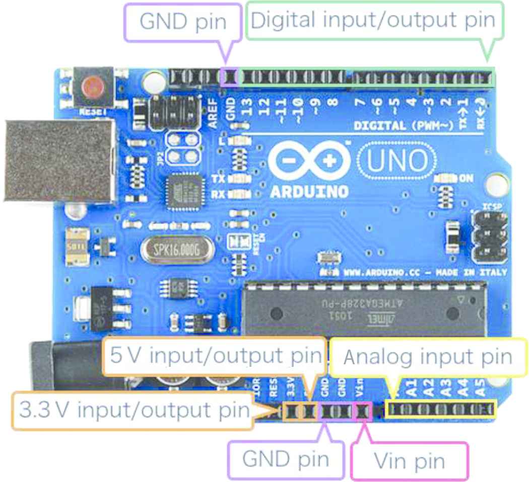
An overview of Arduino Uno.
Arduino can be easily designed by using it with breadboard. Figure 2 shows an overview of a breadboard. The breadboard is a board which does not require soldering and that can design a circuit by inserting a jumper wire or a module into a hole on the board. The current conducting section of the breadboard is on the red line in Figure 2.

An overview of a breadboard.
In Arduino, depending on the circuit designed by a user, it is possible to design the circuit that damages Arduino itself on it. Specifically, there are the followings:
- •
A risk of overvoltage when output pins are connected.
- •
A risk of damaging the blocking diode in the Arduino itself when the voltage exceeding 3 V is sent to the input pin.
- •
A risk of overcurrent if the input pin receives an electric current exceeding 200 mA.
In the implementation of ADVIS in this paper, only the first and second risks as above can be detected.
3. ARDUINO SIMULATOR ADVIS
The requirements of ADVIS is as follows:
- •
iPad Pro 12.9 (second generation).
- •
iOS 10+.
Figure 3 shows an overview of ADVIS. ADVIS consists of the following three parts:
- •
Circuit design part.
- •
Module selection part.
- •
Menu part.
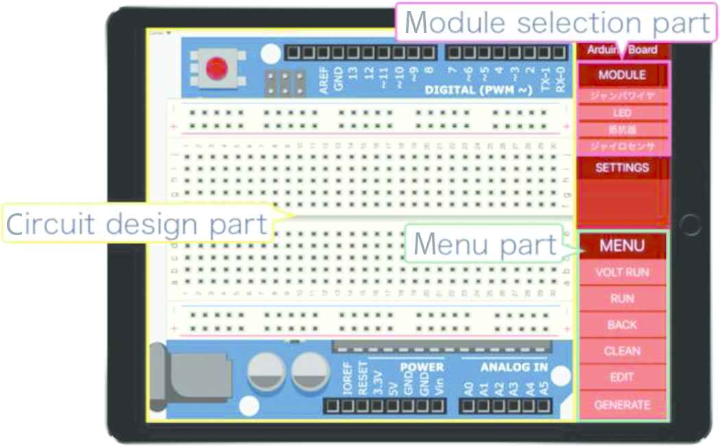
An overview of ADVIS.
3.1. Circuit Design Part
In the circuit design part, a circuit is designed using jumper wires, LEDs, and resistors.
3.2. Module Selection Part
In the module selection part, a module to be handled in for the circuit design part is selected. ADVIS can handle jumper wires, LEDs, and resistors only. The LED has a resistance value of 100 Ω, and when a voltage of 3 V or more flows, the LED lights up in green. The resistor has a resistance value of 150 Ω.
3.3. Menu Part
In the menu part, it is implemented the “CLEAR” function, the “BACK” function, the “RUN” function, and the “VOLT RUN” function.
Using the “CLEAR” function removes all modules that are placed in the circuit design part and returns to the initial state.
Using the “BACK” function returns the circuit design part to its previous state. Here, immediately after using the “CLEAR” function, you cannot use the “BACK” function.
Using the “RUN” function, the designed circuit is executed to detect the risk of module breakage. Figure 4 shows an example of the “RUN” function (Here, the image is edited for easy-to-read). When the risk of a module breakage is detected, highlight the input pin of the module in red.
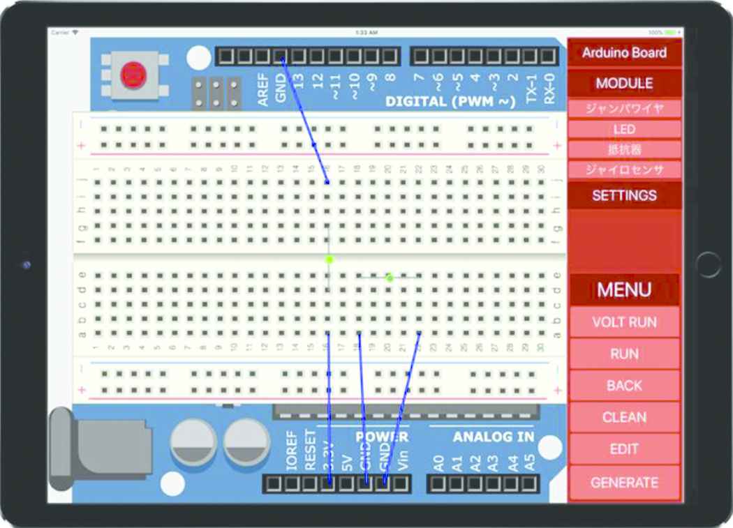
Example of the “RUN” function.
Using the “VOLT RUN” function displays the value of voltage on the designed circuit. Figure 5 shows an example of the “VOLT RUN” function (Here, the image is edited for easy-to-read).
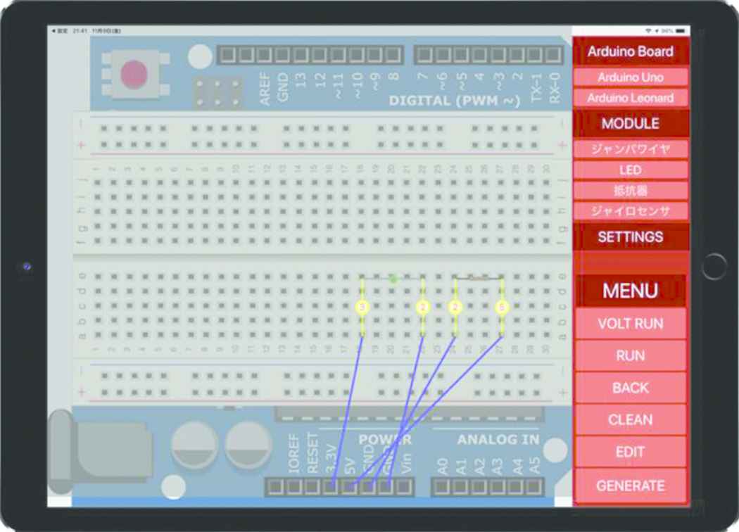
Example of the “VOLT RUN” function.
3.4. Function of ADVIS
In ADVIS, in addition to the risk of damaging the Arduino itself described in Section 2, the risk of damaging the module can be detected. It is target module is only LED. LED is damaged if it receives voltage more than 3 V.
4. VERIFICATION OF ADVIS
It is confirmed that ADVIS can simulate correctly the designed circuit. The followings are verified:
- •
Displaying of the value of voltage on the circuit.
- •
Detecting a risk of Arduino itself being damaged.
- •
Detecting a risk of module being damaged.
4.1. Displaying of Value of Voltage on the Circuit
To display the value of voltage on the circuit, it can be displayed by using the “VOLT RUN” function. As an example, connect 5 V pin and Vin pin to the breadboard, respectively. Figure 6 shows the result that the “VOLT RUN” function is executed.
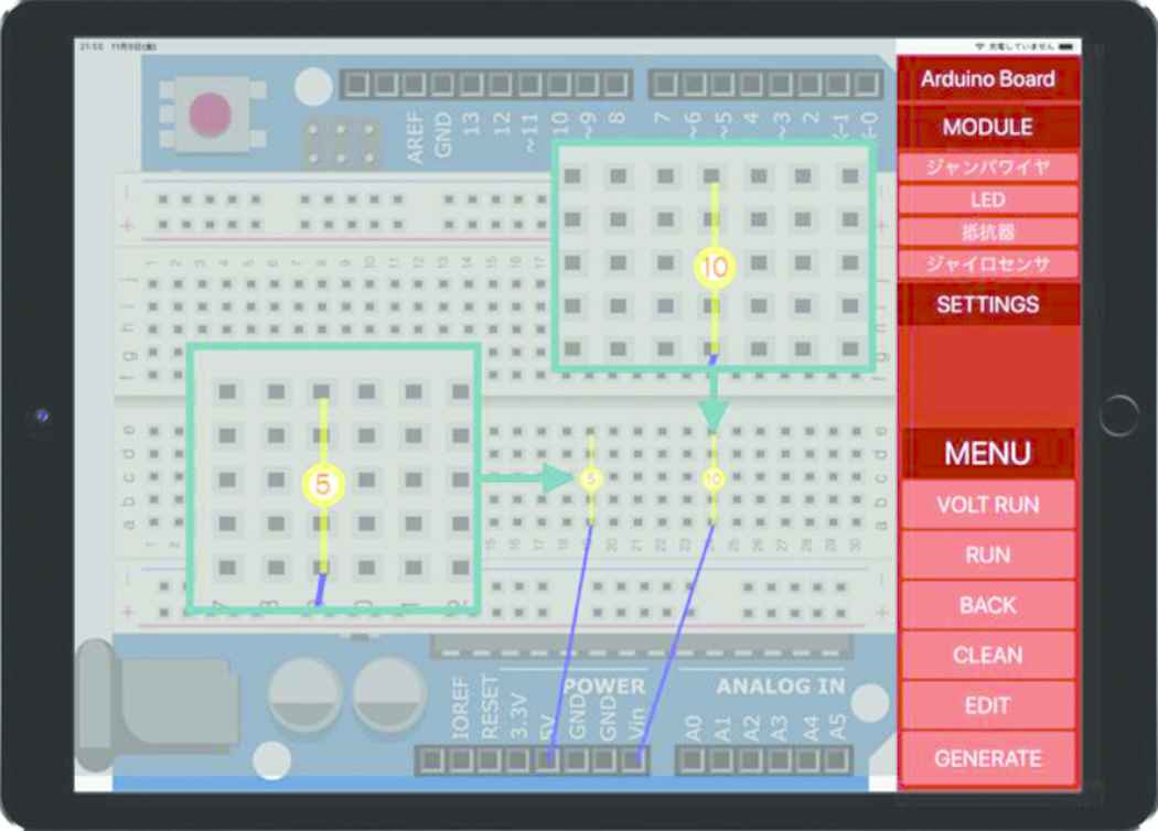
Displaying the value of voltage on the circuit.
From Figure 6, 5 V is displayed on the circuit connected to the 5 V pin, and 10 V is displayed on the circuit connected to the Vin pin.
Next, the resistor and the 5 V pin to the breadboard are connected. Figure 7 shows the result that the “VOLT RUN” function is executed.
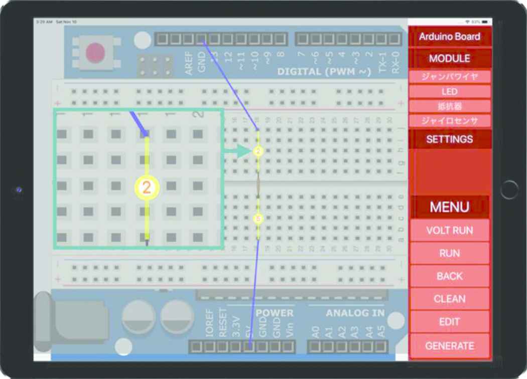
Displaying of value of voltage using resistor.
From Figure 7, 5 V is displayed on the circuit, and 2 V, which is calculated from Ohm’s law (V = 0.02 × 150), is displayed on the circuit.
Therefore, it can be confirmed that ADVIS displays the value of voltage.
4.2. Detecting a Risk of Arduino Itself Being Damaged
In order to detect where there is a risk of corruption of Arduino itself, it can be displayed by using the “VOLT RUN” function. As an example, connect 5 V pin and Vin pin to input/output pins. In this circuit because the voltage exceeding 3 V is followed to the input pin, there is a risk that the blocking diode of the Arduino itself will be damaged. Figure 8 shows the result that the “VOLT RUN” function is executed.
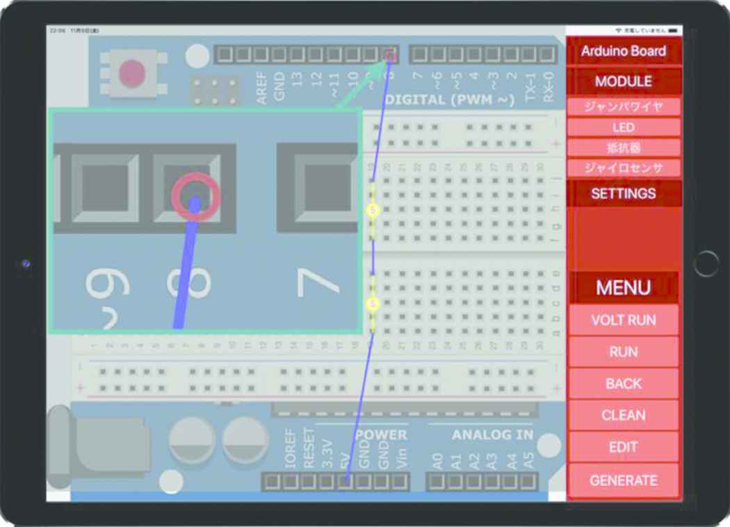
Detecting a risk of Arduino itself being damaged.
From Figure 8, ADVIS can display the Arduino input/output pins in red when the risk that the Arduino itself is damaged is detected.
4.3. Detecting a Risk of Module Being Damaged
To detect where there is a risk of corruption of modules, it can be displayed by using the “RUN” function. As an example, connect the LED to the 5 V pin. In this circuit, there is a risk of damaging the LED because it receives the value of voltage higher than 3 V. Figure 9 shows the result that the “RUN” function is executed.
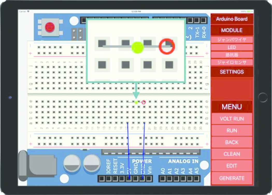
Detecting a risk of the module being damaged.
From Figure 9, ADVIS can display the input pin in red when the risk that the module is damaged is detected.
5. CONCLUSION
This research has implemented an Arduino simulator ADVIS that runs on iPad for supporting to design a circuit. The implemented ADVIS has the following functions:
- •
Designing a circuit on Arduino.
- •
Visualizing the value of voltage in the circuit.
- •
Detecting a risk of Arduino itself being damaged.
- •
Detecting a risk of module being damaged.
It can be confirmed that the above functions can be implemented correctly. Consequently, ADVIS can support to design a circuit. Future issues are as follows:
- •
Save function of the designed circuit.
- •
Circuit control by programming.
- •
A function to automatically generate a program based on the designed circuit.
- •
Implementation of resistors with various values and other modules.
Authors Introduction
Tetsuro Katayama
 Tetsuro Katayama received the PhD degree in engineering from Kyushu University, Fukuoka, Japan in 1996. From 1996 to 2000 he has been a Research Associate at the Graduate School of Information Science, Nara Institute of Science and Technology, Japan. Since 2000 he has been an Associate Professor at Faculty of Engineering, Miyazaki University, Japan. He is currently a Professor with the Faculty of Engineering, University of Miyazaki, Japan. His research interests include software testing and quality. He is a member of the IPSJ, IEICE, and JSSST.
Tatsumi Nishida
 Tatsumi Nishida received the Bachelor degree in Information Science from Kyushu Sangyo University, Fukuoka, Japan in 2018. He is currently a Graduate School of Engineering, University of Miyazaki, Japan.
Yoshihiro Kita
 Yoshihiro Kita received a PhD degree in systems engineering from University of Miyazaki, Japan, in 2011. He is currently an Assistant Professor with the Computer Science, Tokyo University of Technology, Japan. His research interests software testing and biometric authentication.
Hisaaki Yamaba
 Hisaaki Yamaba received the B.S. and M.S. degrees in chemical engineering from Tokyo Institute of Technology, Japan, in 1988 and 1990, respectively, and the PhD degree in systems engineering from University of Miyazaki, Japan, in 2011. He is currently an Assistant Professor with the Faculty of Engineering, University of Miyazaki, Japan. His research interests include network security and user authentication. He is a member of SICE and SCEJ.
Kentaro Aburada
 Kentaro Aburada received the B.S., M.S., and PhD degrees in computer science and system engineering from the University of Miyazaki, Japan, in 2003, 2005 and 2009, respectively. He is currently an Associate Professor with the Faculty of Engineering, University of Miyazaki, Japan. His research interests include computer network and security. He is a member of IPSJ and IEICE.
Naonobu Okazaki
 Naonobu Okazaki received his B.S., M.S., and PhD degrees in electrical and communication engineering from Tohoku University, Japan, in 1986, 1988 and 1992, respectively. He joined the Information Technology Research and Development Center, Mitsubishi Electric Corporation in 1991. He is currently a Professor with the Faculty of Engineering, University of Miyazaki since 2002. His research interests include mobile network and network security. He is a member of IPSJ, IEICE and IEEE.
REFERENCES
Cite this article
TY  - JOUR
AU  - Tetsuro Katayama
AU  - Tatsumi Nishida
AU  - Yoshihiro Kita
AU  - Hisaaki Yamaba
AU  - Kentaro Aburada
AU  - Naonobu Okazaki
PY  - 2019
DA  - 2019/03/30
TI  - Implementation of Arduino Simulator ADVIS Visualizing the Value of Voltage on the Circuit
JO  - Journal of Robotics, Networking and Artificial Life
SP  - 249
EP  - 252
VL  - 5
IS  - 4
SN  - 2352-6386
UR  - https://doi.org/10.2991/jrnal.k.190220.009
DO  - 10.2991/jrnal.k.190220.009
ID  - Katayama2019
ER  -