
Development of Dam Inspection Underwater Robot
- DOI
- 10.2991/jrnal.k.190531.004How to use a DOI?
- Keywords
- Underwater robot; dam inspection; underwater robot positioning; remotely operated vehicle
- Abstract
The maintenances of social infrastructures such as dams and bridges are important subjects. The older the infrastructure becomes, the more need there is for effective inspection methods. In the inspection of the underwater dam structure, divers can be used, but the inspection result is insufficient. We developed an underwater inspection robot for use not only with dams, but in bridges, etc. It can do video capture, indirect measurement using a laser, depth and heading keeping as well as having other functions too. The underwater inspection robot was tested in an actual dam inspection where it showed its’ effectiveness.
- Copyright
- © 2019 The Authors. Published by Atlantis Press SARL.
- Open Access
- This is an open access article distributed under the CC BY-NC 4.0 license (http://creativecommons.org/licenses/by-nc/4.0/).
1. INTRODUCTION
Social infrastructure projects, such as dams and bridges, require a great deal of cost and time for restoration and conservation. Deterioration due to aging is progressing on many projects built during the high economic growth period [1]. It is for this reason, there is a need for more efficient maintenance methods to be used on these structures. The underwater inspection work of dams and bridges is particularly difficult and has not been widely done because visual confirmation by a diver is restricted for safety [2]. To solve such problems, inspection methods utilizing underwater robots have been developed and researched [3–6].
The authors have developed and researched the use of an underwater inspection robot with the aim of replacing or supporting diver inspection work. The underwater inspection robot can move underwater, do image photographing, determine object size via indirect measurement and maintain its’ positioning against the structure being inspected.
The underwater robot technology was applied in the underwater examination of an actual dam which was participating in the ‘Verification field of the next generation social infrastructure robot’ study and was publicly invited by Ministry of Land, Infrastructure and Transport to give a demonstration in 2015.
2. DAM INSPECTION UNDERWATER ROBOT
2.1. Configuration of the System
In the development of the underwater inspection robot, we focused on the importance of time and in trying to minimize the amount of effort needed for preparation in the field. Figure 1 presents how the system looks and Figure 2 shows the system configuration diagram of the three elements which comprise the robot. These include the Remotely Operated Vehicle (referred to as the ROV), the ground station and the floating unit.

The dam inspection underwater robot.

System architecture of ROV.
The ground station is operated on land and is connected to the ROV situated underwater by a neutral buoyancy cable. Between these two elements, power is transmitted and communication is performed via a power line called the Power Line Communication.
The floating unit communicates to the ground station wirelessly using ZigBee protocols.
2.2. Remotely Operated Vehicle
The appearance of the ROV is shown in Figure 3. The ROV has an azimuth sensor, a depth sensor and a USB camera. Numerical value acquisition is possible when using the sensors, while the operation of the motor driver and video from the USB camera, as well as the photographing of still pictures and LED lighting are carried out by a built-in, on-board computer housed on the ROV.
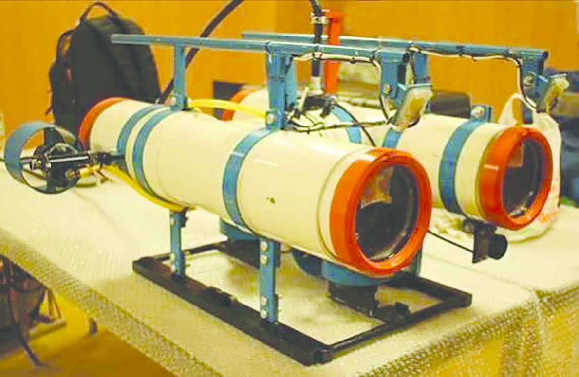
Overview of ROV.
2.3. Floating Unit
The appearance of the floating unit is shown in Figure 4. The floating unit operates with batteries and is connected to the ROV via fishing line. By sending out the fishing line, according to the movement of the ROV and in keeping a constant tension on the line itself, the floating unit corresponds to the horizontal position of the ROV. In addition, it incorporates a GPS and transmits the output value to the ground station via ZigBee protocols.

Overview of floating unit.
2.4. Ground Station
Figure 5 shows the contents displayed on the ground station computer during operation. The contents displayed are an image from the surveillance camera installed in the ROV, the shipboard camera, and the sensor output. As soon as the system is turned on, it automatically starts recording the display contents.
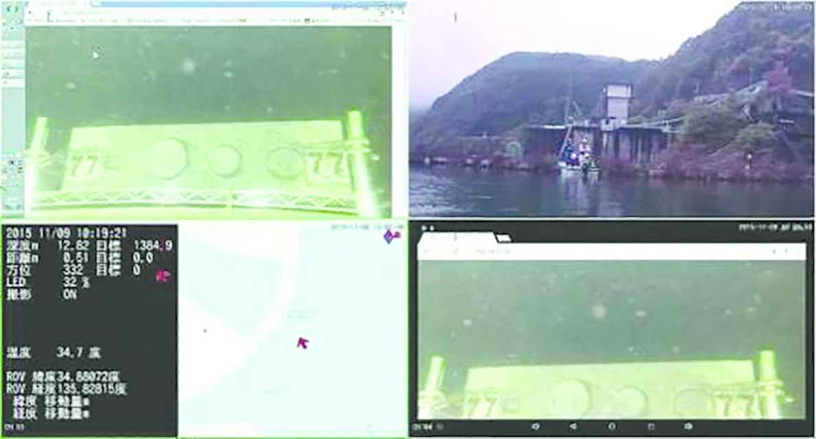
Display contents of ground station.
Only the sensor output screen is shown in Figure 6. It is understood that the ROV and the sensor output acquired from the floating unit are displayed in Japanese on the left side. Meanwhile, on the right side, based on the sensor, the horizontal position of the ROV and the heading are displayed on the map.
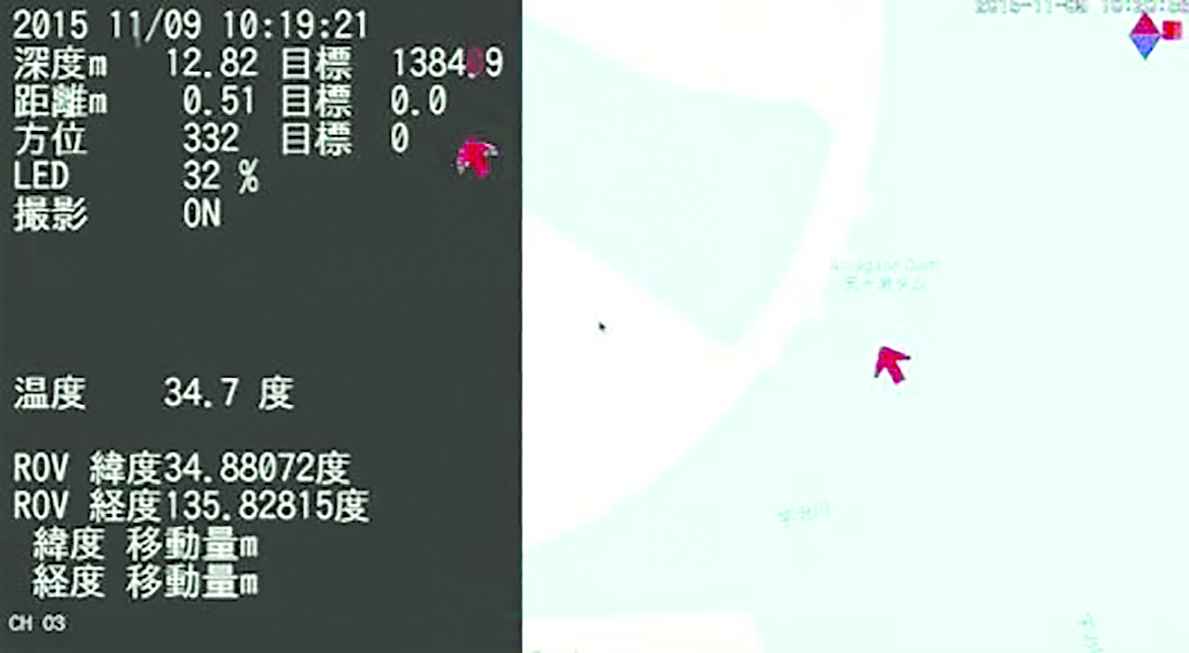
Display sensor output of ground station.
3. UNDERWATER INSPECTION METHOD
3.1. Outline of the Inspection Method
When an inspection is done using the underwater inspection robot, such as on a dam, not only is the underwater structure being continuously photographed with the built-in camera, but also the coordinates and location of the object are simultaneously being recorded. Photographs which have a wide range can also be made smoothly and continuously via a position keeping function connected to a feedback control function mounted on the ROV. Furthermore, in post processing, the size of an image can be accurately measured and estimated if it is necessary.
3.2. Estimation of Shooting Coordinates
The output values of the GPS mounted on the floating unit, along with the output values of the depth sensor, the orientation sensor and the underwater distance sensor, which is mounted on the ROV, are all recorded with the same time stamp. The coordinates of the object at the time of camera shooting can be estimated in post processing. We measured the positioning error at the first grade national control points of the Geospatial Information Authority of Japan. The result of performing a recording for 3 min after the start of a stable GPS was as follows in the X-coordinate, a maximum of 22 cm difference, while in the Y-coordinate, the difference was a maximum of 93 cm in the Plane Rectangular Coordinate System of JGD2011. This means there was an error of 63 cm straight distance on average.
3.3. Estimation of Size of Photographing Object
The size of the object can be indirectly estimated by using the fixed laser mounted on the ROV. The fixed laser is composed of two pieces and the interval distance was set to 300 mm. The size of the object photographed is calculated by deriving the dimension for each pixel from the interval of the laser photographed in the image.
Figure 7 shows the result of calculating the size of the object to be photographed from the image. In Figure 7, the red line shows the distance between two points of a fixed size laser, and the blue line shows the size of the calculated object.

Calculated object size result.
3.4. Stabilize the Attitude
In order to maintain the positional relationship with the object to be photographed, feed-back control is used to stabilize the attitude of the ROV. Depth, azimuth, and horizontal distance from the dam wall are controlled. PID control was used for feedback control, and the control gain was adjusted by actual movement in a preliminary test. In the maintenance control of the horizontal distance from the dam wall, it is necessary for the underwater distance sensor to be opposite to the dam wall. This can be performed simultaneously with the maintenance control of the azimuth.
4. EVALUATION AT ACTUAL DAM INSPECTION
To confirm the effectiveness of the underwater inspection robot, we conducted a test at the Amagase Dam in Kyoto Prefecture on November 24, 2015. Amagase Dam is an arched concrete dam. The state of the test at the Amagase Dam is shown in Figure 8.

Amagase Dam and boat.
In Figure 8, a dam wall is on the right hand side, and a boat for inspection is visible in the center.
The inspection target in the test is to check the position coordinates, the surface shape, and the size by photographing the concrete block installed in the preliminary conduit gate in the state of falling into the water. The number, position and shape of the concrete blocks were not announced in advance.
In the test, the ROV dropped from the boat was brought close to the dam wall and began the submerge using the guide rail of the preliminary conduit gate exposed on the water as a marker.
Figure 9 shows the state of the boat and the ROV at the start of the inspection. In Figure 9, we see the ROV and floating unit on the water surface indicated by the red circle. We submerged the ROV by manual operation and attempted maintenance by autonomous control about heading and horizontal distance from the dam wall.
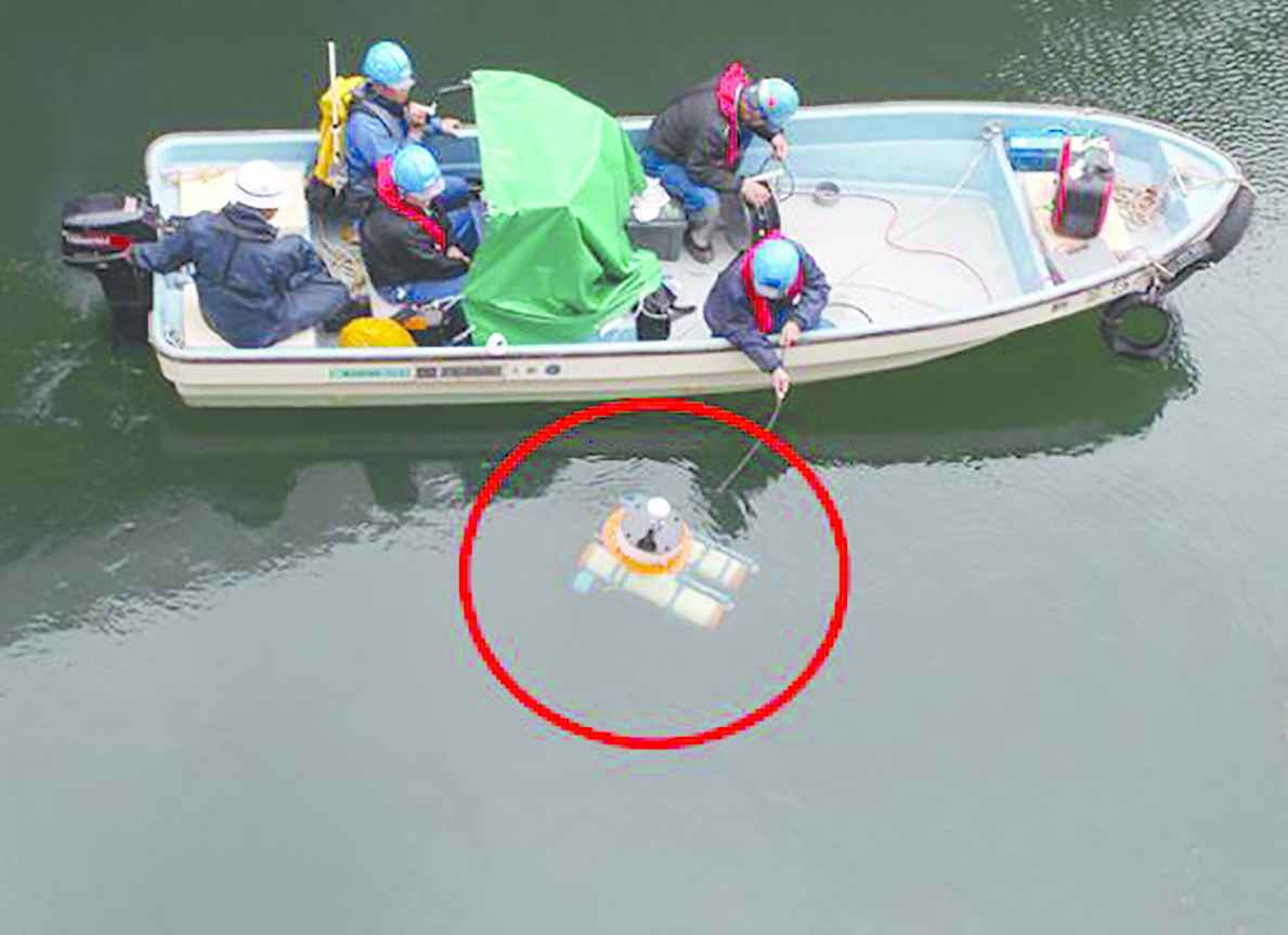
Approach to dam with ROV.
As a result of the test, we succeeded in photographing all concrete blocks within a working time of about 3 h. The number of concrete blocks was four. On the surface of each concrete block, 12 protrusions imitating cracks were engraved. We were able to confirm this using the underwater inspection robot. In addition, we were also able to estimate the size of imitating cracks from the captured image, respectively.
Figure 10 shows the still pictures of four concrete blocks found by the ROV. In Figure 10, you can see that one number, either Figure 10 shows 5 in (a), 7 in (b), 77 in (c), or 9 in (d) are imprinted on the concrete blocks themselves.
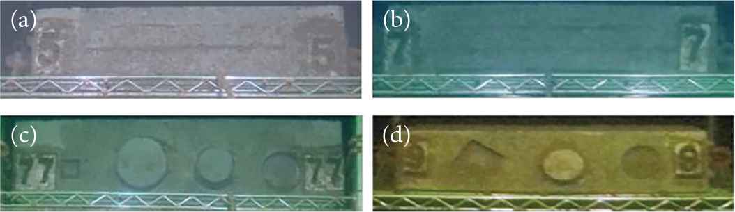
Inspection concrete block and imitating cracks.
Table 1 shows the measured results from the sensor output values at the time of shooting and the setting values of the global position coordinates of the four concrete blocks. In addition, the global position is based on the Plane Rectangular Coordinate System of JGD2011.
| Concrete block | Global position (JGD2011 VI plane rectangular coordinates) | |||
|---|---|---|---|---|
| Figure | X (m) | Y (m) | Difference (m) | |
| 5 | Measured position | −124157.849 | −15709.042 | 0.462 |
| Setting position | −124157.410 | −15709.211 | ||
| 7 | Measured position | −124155.629 | −15709.953 | 0.470 |
| Setting position | −124155.226 | −15710.195 | ||
| 9 | Measured position | −124155.630 | −15709.039 | 0.599 |
| Setting position | −124155.139 | −15709.383 | ||
| 77 | Measured position | −124156.738 | −15709.955 | 0.650 |
| Setting position | −124156.131 | −15710.188 | ||
Measurement results
As shown in Table 1, the difference between the measured and the setting value of each coordinate is small, the inspection result using the underwater inspection robot at this dam shows it can endure practical use.
5. CONCLUSION
In the verification test using the underwater inspection robot, we were able to estimate the coordinates of the shooting position using a still image of the concrete block installed in the dam wall, and succeeded to confirm the imitating cracks on the concrete block surface.
As a result, the efficient underwater inspection work of the actual dam was possible using the underwater inspection robot.
CONFLICTS OF INTEREST
There is no conflicts of interest.
ACKNOWLEDGMENT
This research is promoted by the Nissui Marine Kogyo Co., Ltd.
Authors Introduction
Mr. Hiroyasu Hirai
 He was born in Oita, Japan, in 1988. He received his B.E., M.E., in Computer Science from Nippon Bunri University, Japan, in 2013, 2016, respectively. He is a 2nd year student in the doctoral program of the Kyushu Institute of Technology. He is an engineer of Garuda incorporated in 2016. His research interest includes autonomous robotics and machine learning. He is a member of The Robotics Society of Japan and the Japan Society of Mechanical Engineers.
Dr. Kazuo Ishii
 He is a Professor in the Kyushu Institute of Technology, where he has been since 1996. He received his PhD degree in engineering from University of Tokyo, Tokyo, Japan, in 1996. His research interests span both ship marine engineering and Intelligent Mechanics. He holds five patents derived from his research. His lab got “Robo Cup 2011 Middle Size League Technical Challenge 1st Place” in 2011. He is a member of the Institute of Electrical and Electronics Engineers, the Japan Society of Mechanical Engineers, Robotics Society of Japan, the Society of Instrument and Control Engineers and so on.
REFERENCES
Cite this article
TY  - JOUR
AU  - Hiroyasu Hirai
AU  - Kazuo Ishii
PY  - 2019
DA  - 2019/06/25
TI  - Development of Dam Inspection Underwater Robot
JO  - Journal of Robotics, Networking and Artificial Life
SP  - 18
EP  - 22
VL  - 6
IS  - 1
SN  - 2352-6386
UR  - https://doi.org/10.2991/jrnal.k.190531.004
DO  - 10.2991/jrnal.k.190531.004
ID  - Hirai2019
ER  -