
User Interface and Motion Planner for Task Database
- DOI
- 10.2991/jrnal.k.200222.008How to use a DOI?
- Keywords
- Robotic assembly; motion planning; task planning; database
- Abstract
In this paper, we present user interface modules for handing task motion data on robotic manipulation. The database covers robot motion, human motion and object information. The authors especially present its data structure, data registration, data search, Graphical User Interface (GUI), and Application Programming Interface (API). The task motion data is registered using vision sensor and GUI. The robot work motion is generated automatically with planning module and modification module.
- Copyright
- © 2020 The Authors. Published by Atlantis Press SARL.
- Open Access
- This is an open access article distributed under the CC BY-NC 4.0 license (http://creativecommons.org/licenses/by-nc/4.0/).
1. INTRODUCTION
Most robots repeat a determined motion in mass production. However, in the case of variable production, it is necessary to teach a new motion to robot according to changes in the product. It is said that robot teaching and device setting costs are much larger than the cost of the robot body. Therefore, frequently teaching robot motions and changing devices according to product changes will lead to a significant increase in cost.
Human flexibly realize a wide variety of tasks. It is considered that the experiences of various tasks are abstracted, conceptualized, and accumulated as skills and knowledge. Then the skills and knowledge are applied to new tasks.
The authors have constructed a cloud database [1–4] that accumulates various information related to motions and shares among robots for motion generation. The database accumulates human work motions and teaching data for robots, work procedure, and object information such as the shape of the object, motion trajectories during work.
This research aims to construct the database for a robot adaptively performing a task. Figure 1 shows the overview of its framework. The database is composed of the object data and teaching motion data. When a robot performs a novel task, a robot download and modify the data so as to fit the novel task.
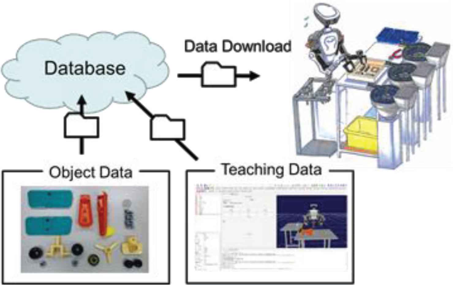
Framework on motion generation of industrial robot from database where the database includes information on object data and teaching motion data.
2. THE STRUCTURE OF THE DATABASE
The structure of database is designed by considering versatility and reusability. The motion is described by the sequence of coordinates of the object and is independent of the configuration of robot. A motion can be shared in general robots. The hierarchical description makes it possible for robots to reuse appropriate level of motion.
An assembly of a product is composed of multiple task elements where each task element is composed of a set of motion sequence. Therefore, the first, the second and the third layers are respectively named as “work”, “task” and “action” layers. Since multiple objects are related in a single action, two objects are named as follows. The object held by a robot is named as the “main object” and the object assembled to the main object is named as the “sub object”. The action data include the trajectory which is the time series of relative posture of the main object and the sub object. If the position of the sub object changes, the motion is adapted using the relative postures in the action data. The three layers are effective for reusing motion. For example, the action “tightening screw” can be used in another task data. The task data can also be used in another work.
Figure 2 shows an example of assembly of a toy airplane. The task is “fixing the wing to the body” and composed of two actions: “put the wing on the body”, and “put and rotate the screw”. At the first action, the main object is the upper wing and the sub object is the upper body. At the second action, the main object is the screw and the sub object is the upper wing.
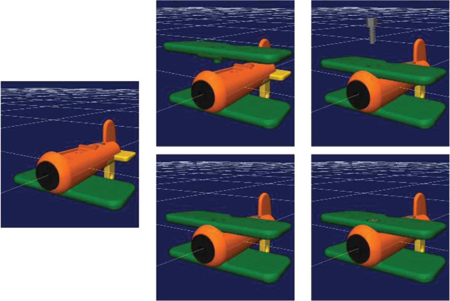
An example of task for toy assembly.
The following is a set of information included in the database:
- •
Motion strategy (A sequence of task/motion)
- •
Human (Identified name etc.)
- •
Robot (Name, type, hand)
- •
Object name
- •
Object category
- •
Object shape
- •
Object parameters (Mass, CoG, material, stiffness, etc.)
- •
Grasping configuration (Main object)
- •
Fixture configuration (Sub object)
- •
Time series of the main object’s pose w.r.t the sub object
- •
Control method and its parameters
- •
Force information applied by the hand
The data can be obtained by several methods such as a human motion capture and a motion generation tool. The data is stored in the YAML format where some examples are shown in Figure 2. YAML is a human-readable data-serialization language.
3. INTERFACES OF DATABASES
3.1. Motion Searching Function
Figure 3 shows the searching function of the motion database plugin. As keywords used for the search, we set the name of parts, the category of parts, the feature of object data, and object’s weight. Inputting keywords in the search window, we obtain the candidates of objects and motion data. The Figures 3 and 4 show an example where we search the keyword “shaft” and obtained the object model “shaft1” and “shaft2” and corresponding motion data.
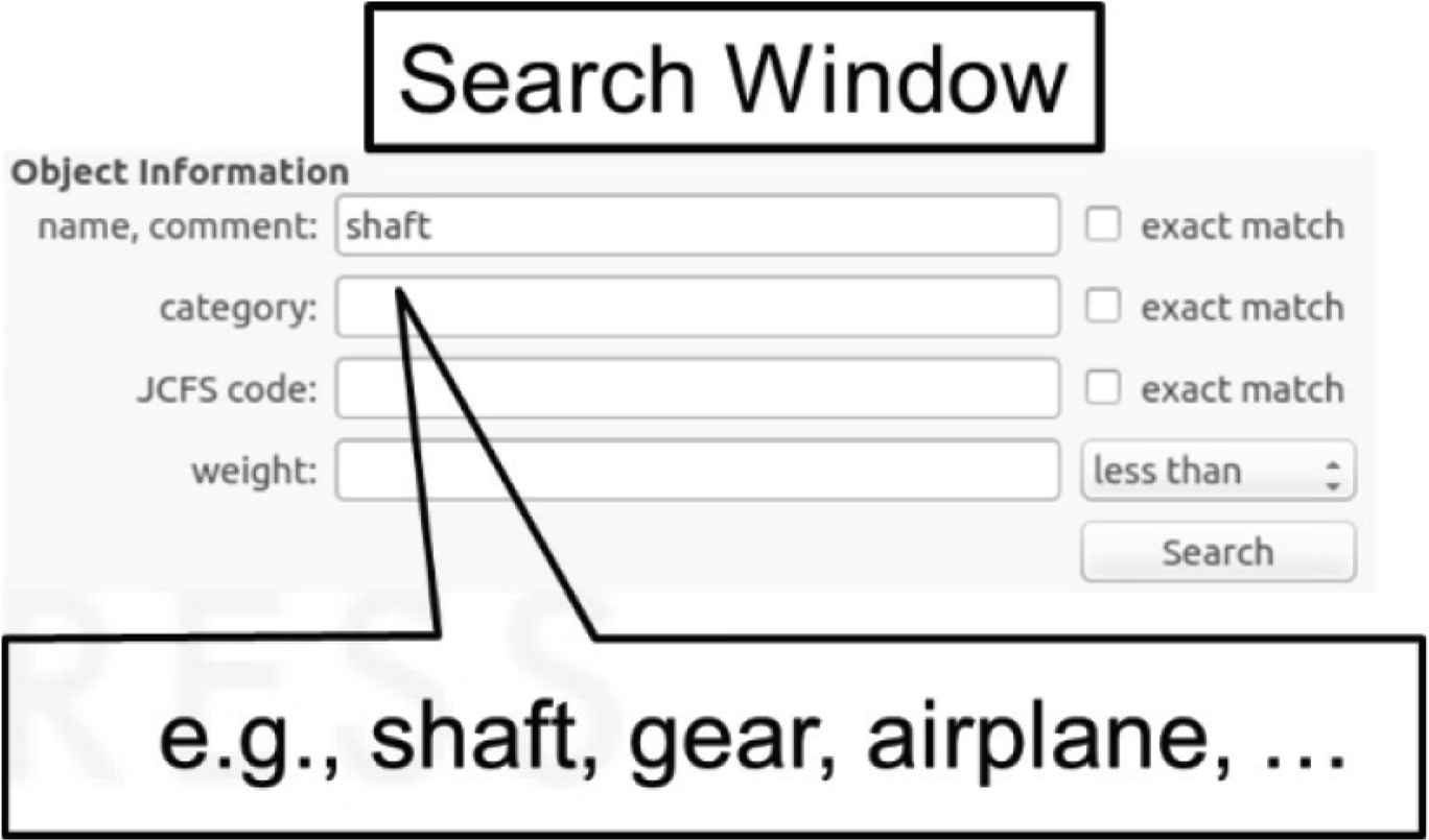
Search window for the database.
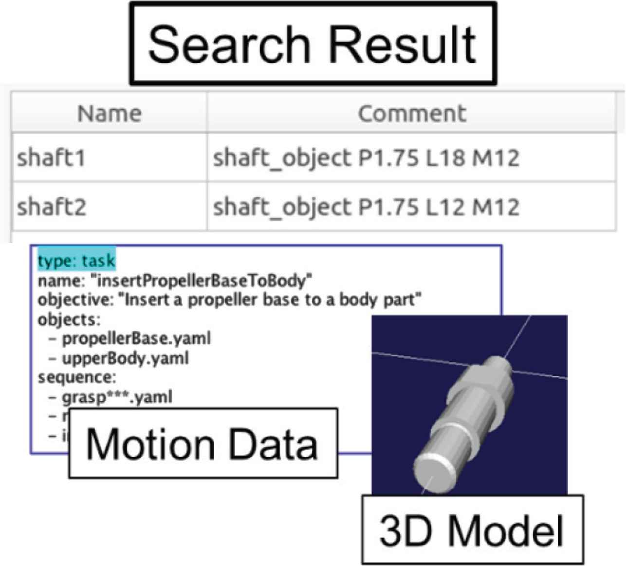
Search result of task database.
3.2. Object Trajectory of Human Motion
Vision sensor is used generating action data. The trajectory of an object is measured by vision and stored to the database. In Figure 5, an example is shown. A depth camera is used for measuring the position of a plastic bottle. The trajectory of a plastic bottle grasped by human is stored to the database as an action data. After a robot plans the grasping position on the plastic bottle, the robot moves the same trajectory of human.
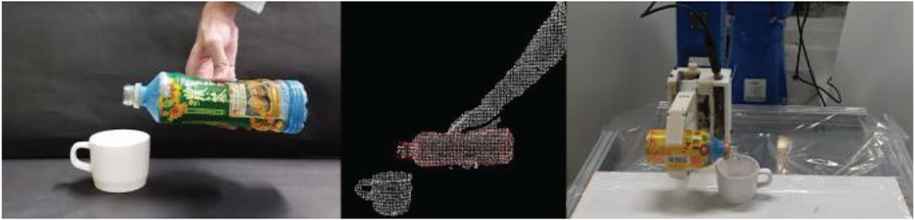
Vision system for measuring object motion grasped by human and robot motion generation using the motion data.
3.3. Graphic User Interface
Graphic user interface of Choreonoid is implemented for registering the action data in the database. The main object and the sub object can be selected by clicking a button on the window. The object position of the main object can be operated by mouse motion and be set with the value. The trajectory of the main object is saved as YAML file.
The grasp position can be registered manually using the graphic interface. The robot motion can be generated according to the motion of the object.
4. MOTION GENERATION USING DATABASE
4.1. Motion Planning for Generating Task Motion
The authors have implemented motion planner. Robot motion of the task data is generated by using grasp planning and path planning [5]. The hand position on the object position is determined by grasp planning. The path planning is used for connecting the ends of multiple actions. After once grasp position of the main object is determined, the robot motion is generated automatically according to the motion of the main object. If the hand collides the sub object during an action, grasp position is planned again.
4.2. Motion Modification
Let us explain the feature of objects defined in this research. Figure 6 shows three examples of features. In case of a bolt, diameter, pitch and length are the features. In case of a gear, diameter and the number of teeth are the features. In case of a L shaped object, the dimension of the object is the feature.
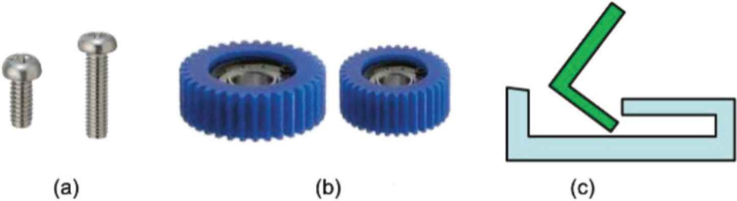
Definition of features. (a) Bolt. (b) Gear. (c) L shaped object.
Figure 7 shows the modification module of motion data.
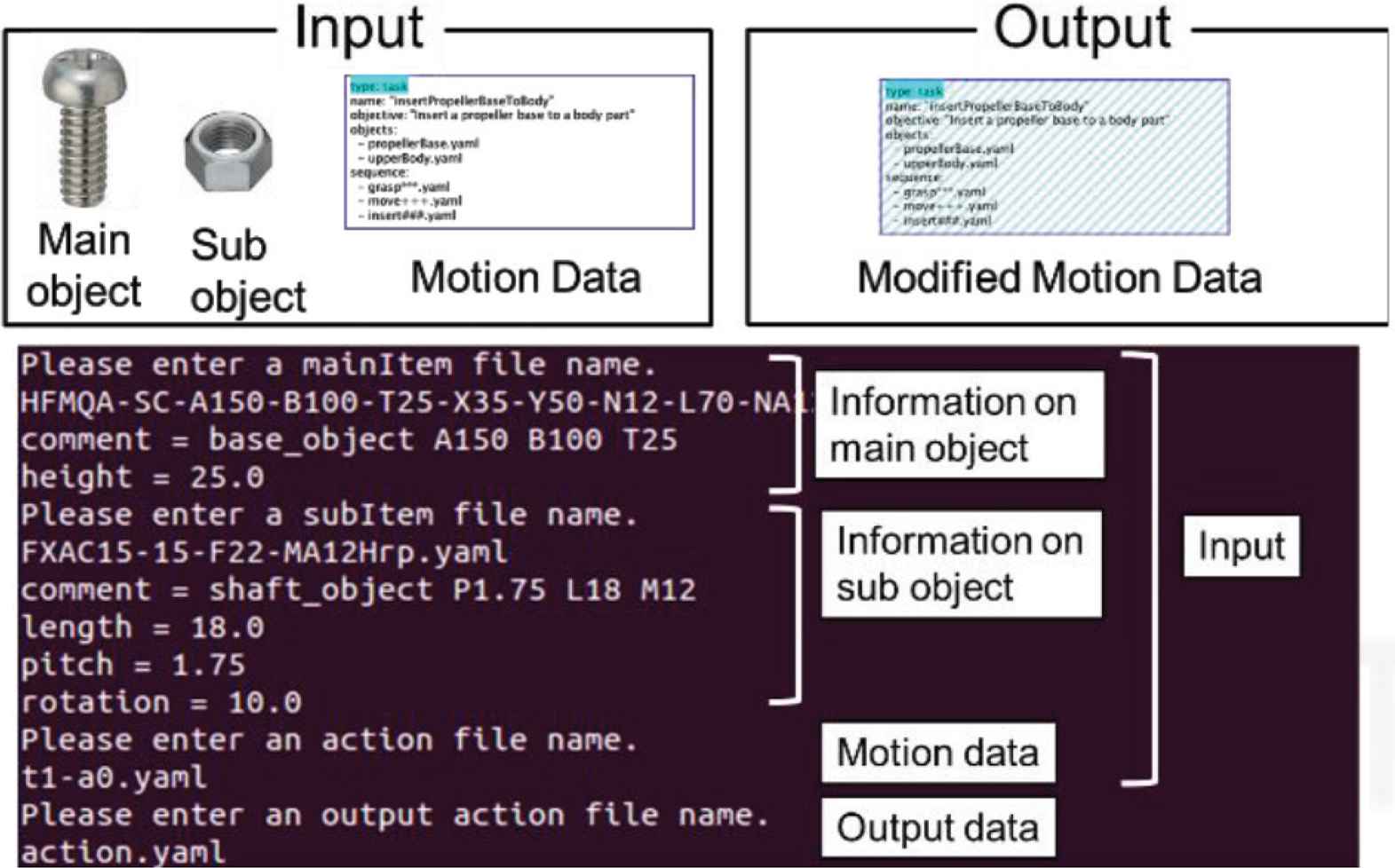
Modification module of motion data.
The inputs to this module are the features of the new main and sub objects and the existing motion data of similar but different object. An example of the main and sub objects, we can consider the bolt and nut. As an example of new objects, we can consider the new bolt with different pitch and length. By considering the difference of feature between objects, we modify the motion data and make it fit to the newly appeared objects.
In our experiment, we used two screwing units with different features as shown in Figure 8. The first unit has the screw length 12 mm and base thickness 15 mm. The second unit has the screw length 18 mm and base thickness 25 mm. We prepared the motion data to assemble the first unit and modify this motion data to fit to the second unit.
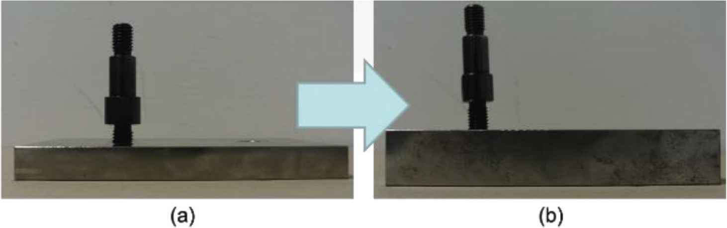
Screwing units used in the experiment. (a) Screwing unit 1. (b) Screwing unit 2.
Figure 9 shows the experimental results. As shown in this figure, the robot adaptively generates the motion data and generates the screwing motion of different screwing unit.
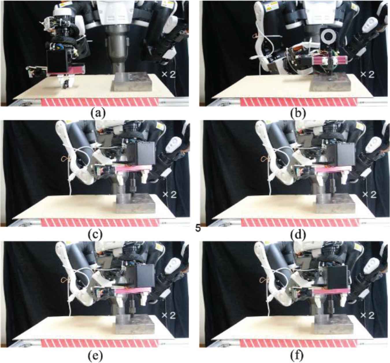
Experimental result of motion modification. (a) The robot grasped the screwing unit. (b) The robot put the screwing unit on the base plate. (c–f) The robot screwed the screwing unit.
5. CONCLUSION
Task database and the interfaces are implemented for robotic motion generation. The task data is independent with the configuration of robots. We designed three layers for task data. The data of each layer can be reused. The GUI and vision sensor is used for storing task data. The robot motion is generated with search module, planner module, and modification module.
CONFLICTS OF INTEREST
The authors declare they have no conflicts of interest.
AUTHORS INTRODUCTION
Prof. Tokuo Tsuji
 He received his Doctoral degrees from Kyushu University in 2005. From 2016, he has been working as an Associate Professor at Institute of Science and Engineering, Kanazawa University.
Dr. Natsuki Yamanobe
 She received the PhD Degree from the University of Tokyo in 2007. She is currently a Senior Research Scientist with Intelligent Systems Research Institute of Advanced Industrial Science and Technology (AIST).
Mr. Kei Ikeda
 He received his Master degrees from Graduate School of Engineering Science, Osaka University in 2019.
Prof. Kensuke Harada
 He received his Doctoral degrees in Mechanical Engineering from Kyoto University in 1997. From 2016, he has been working as a Professor at Graduate School of Engineering Science, Osaka University.
REFERENCES
Cite this article
TY  - JOUR
AU  - Tokuo Tsuji
AU  - Natsuki Yamanobe
AU  - Kei Ikeda
AU  - Kensuke Harada
PY  - 2020
DA  - 2020/02/29
TI  - User Interface and Motion Planner for Task Database
JO  - Journal of Robotics, Networking and Artificial Life
SP  - 258
EP  - 261
VL  - 6
IS  - 4
SN  - 2352-6386
UR  - https://doi.org/10.2991/jrnal.k.200222.008
DO  - 10.2991/jrnal.k.200222.008
ID  - Tsuji2020
ER  -