
Design of a Data-Driven Control System based on Reference Model using Predicted Input/Output Responses
- DOI
- 10.2991/jrnal.k.210922.004How to use a DOI?
- Keywords
- Data-driven control; extended output; predicted data; offline tuning
- Abstract
In recent years, data-driven control schemes that do not require system modeling have been actively studied. These schemes use only a set of experimental data to design a controller that realizes the desired reference output offline. However, it is necessary to consider the output response and the input response since there is a limit of the actuator performance in actual machines. This paper proposes a new data-driven control scheme that can predict the input/output responses of an unknown system in offline using a set of operating data. The effectiveness of the proposed scheme is numerically verified by a simulation example.
- Copyright
- © 2021 The Authors. Published by Atlantis Press International B.V.
- Open Access
- This is an open access article distributed under the CC BY-NC 4.0 license (http://creativecommons.org/licenses/by-nc/4.0/).
1. INTRODUCTION
In industrial systems, data-driven control schemes [1–4] have been actively studied to achieve the desired control performance for the controlled system with unknown structure and parameters. These schemes use only a set of experimental data to design a controller that satisfies the desired control performance specified by the reference model offline. Generally, the reference model is designed to focus on only the output response. However, both input/output responses should be considered in designing the control system because there is a limit of the actuator performance in the actual machine. If the input response could be estimated in advance, it would be very useful in designing the reference model.
The Estimated Response Iterative Tuning (ERIT) scheme [5] has been proposed to predict the input/output response before applying the adjusted control parameters. However, this scheme can only be applied to Two-Degree-of-Freedom (2DOF) control systems. On the other hand, it is important to design One-DOF (1DOF) controller because there are also many 1DOF control systems in industries.
In this paper, the new data-driven control scheme is proposed to design a 1DOF controller considering input response for unknown structure systems. The features of the proposed scheme are as follows:
- (i)
The 1DOF control system design that predicts the input response in advance, even for unknown system.
- (ii)
Adjusting the desired input/output responses with one parameter λ.
Finally, the effectiveness of the proposed scheme is verified in Section 4.
2. OVERVIEW OF THE PROPOSED SCHEME
Figure 1 shows an overview of the proposed data-driven control scheme. In the proposed scheme, the controller is designed by the following procedure:
- (I)
Obtaining the desired predicted data
- (II)
Constructing the reference model Gm(z−1) based on
- (III)
Designing a controller using the reference model Gm(z−1) obtained in (II).
The detailed procedure is explained in the next section.
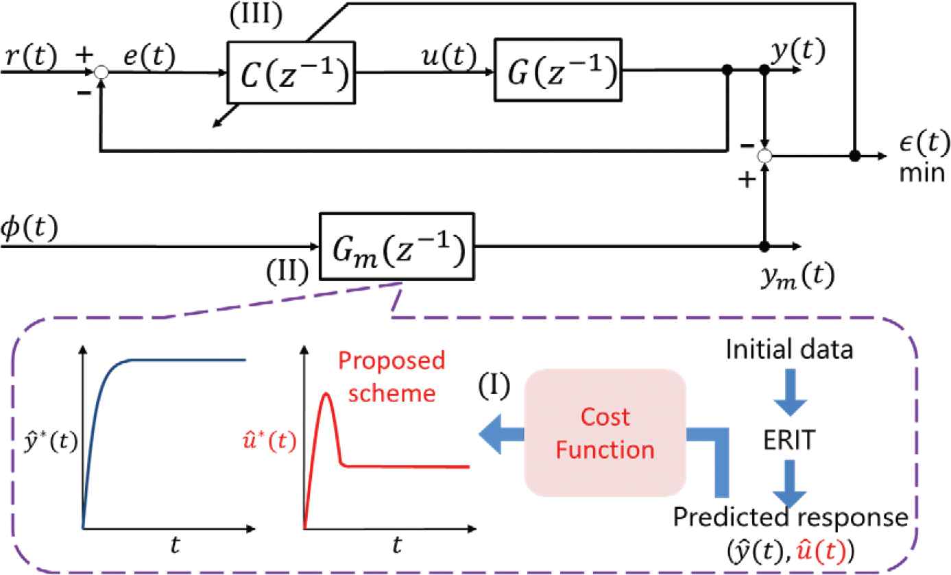
Overview of the data-driven control system by the proposed scheme.
3. DESIGN OF THE CONTROLLER
3.1. Generating Predicted the Data using the ERIT Scheme
In this section, the ERIT scheme [5] is described to generate the predicted data. This scheme is theoretically only applicable to the 2DOF control system. In the proposed scheme, the ERIT scheme is utilized for only predicting the input/output data in Figure 2. Note that the controller is not designed by the ERIT scheme.
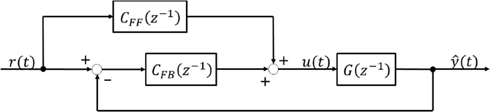
2DOF control system.
First, the initial output y0(t) is obtained in a 1DOF control system. In the case of the feedforward controller CFF(z−1) = 0 in Figure 2, y0(t) is given as follows:
Then, extending to a 2DOF control system for predicting the data, the predicted output ŷ(t) is defined as:
Here, system identification is required to obtain an exactly predicted output ŷ(t) because Equation (2) contains a controlled system G(z−1). Therefore, substituting Equation (1) into Equation (2) yields the following equation:
Consequently, the predicted data ŷ(t) can be derived offline without G(z−1) by using the initial data y0(t) by tuning CFF(z−1). û(t) can also be derived in the same procedure using u0(t) as follows:
From Equations (3) and (4), it is possible to obtain the predicted data ŷ(t) and û(t) offline corresponding to the various CFF(z−1) by using the initial data y0(t) and u0(t). Note that the 2DOF control system was only implemented virtually offline to obtain the predicted data ŷ(t) and û(t).
3.2. Obtaining the Desired Predicted Input/Output Data
In this section, obtaining the desired predicted data
Firstly, r(t) − ŷ(t) in Equation (5) shows the error between the reference signal and the predicted output response. The desired predicted response is obtained by reducing it. Secondly, ∆û(t) = û(t) − û(t − 1) in Equation (5) represents the difference of input response. Therefore, a smaller value of λ increases the responsiveness and a larger value decreases the responsiveness depending on the adjustable parameter λ. Thus, the input/output responses can be easily adjusted with λ. Additionally, it is easy for the user to select the optimal
The adjustment of λ is currently a trial and error process. However, λ can be easily adjusted offline. First, λ is set to 0 in Equation (5). As a result, the predicted input response û(t) is large, because the input term in Equation (5) is not considered. Then, λ is gradually increased to satisfy the desired predicted input/output response ŷ(t) and û(t).
3.3. Design of Gm(z−1) based on the Desired Predicted Data y ^ * ( t )
In this section, Gm(z−1) is designed based on the desired predicted data
Gm(z−1) is designed by minimizing Jref.
3.4. Design of a PID Controller based on the Extended Output ϕ(t)
In this section, a 1DOF controller C(z−1) is designed as an I–PD controller [7] by using the reference model Gm(z−1) that considers the input response obtained in the previous section. It is possible to design the controller by using any data-driven approach. In this paper, the Proportional-Integral-Differential (PID) control scheme based on extended output [8] is used.
I-PD controller is given as follows:
For reasons of space, the details are omitted and refer to the PID control scheme based on extended output ϕ(t) [8].
4. NUMERICAL EXAMPLE
4.1. Controlled System
The effectiveness of the proposed scheme is verified using numerical simulation. The controlled system is the experimental thermal equipment for simulating bag-and-bound welding owned by our laboratory. The model of the system is given as follows:
| H(J/°C) | 12.18 |
| R(°C/W) |
Derived parameters by system identification
The proposed scheme is applied to the system. The reference signal is r(t) = 100(°C), the sampling time is TS = 0.04(s), and the room temperature is d(t) = 20(°C). In this numerical example, I–P controller was used, whose initial proportional and integral gains were set as follows:
Note that the initial PI gains of
Next, the feedforward controller
The order of the denominator was set to second-order because the low order term significantly affects the output response of the controlled system. Furthermore, the value of αi (i = 1, 2, 3) was determined by minimizing Jdes in Equation (5), for example, using the Matlab/Simulink Ver.9.8.0.1396136(R2020a), Optimization Toolbox ’fminsearch.m’.
Furthermore, Gm(z−1) was determined as follows:
Finally, the tuned proportional gain
In this numerical example, the control results are compared by changing λ in Equation (5), and Table 2 shows the feedforward controller
| λ = 0.5 | λ = 5 | |
|---|---|---|
| α1 | 2.55 × 10⁻² | 3.64 × 10⁻³ |
| α2 | −1.30 | −1.01 |
| α3 | 3.25 × 10⁻¹ | 1.77 × 10⁻² |
| θ1 | −4.08 × 10⁻⁴ | −2.24 × 10⁻⁴ |
| θ2 | 4.76 × 10⁻⁴ | 2.39 × 10⁻⁴ |
| θ3 | −1.98 | −1.99 |
| θ4 | 9.80 × 10⁻¹ | 9.93 × 10⁻¹ |
| 6.18 | 2.12 | |
| 2.08 × 10⁻² | 4.77 × 10⁻³ |
Obtained parameters in the simulation
4.2. Control Result
Figures 3 and 4 show simulation results corresponding to the cases of λ = 0.5 and 5, where y0(t) and u0(t) denote initial I/O data,
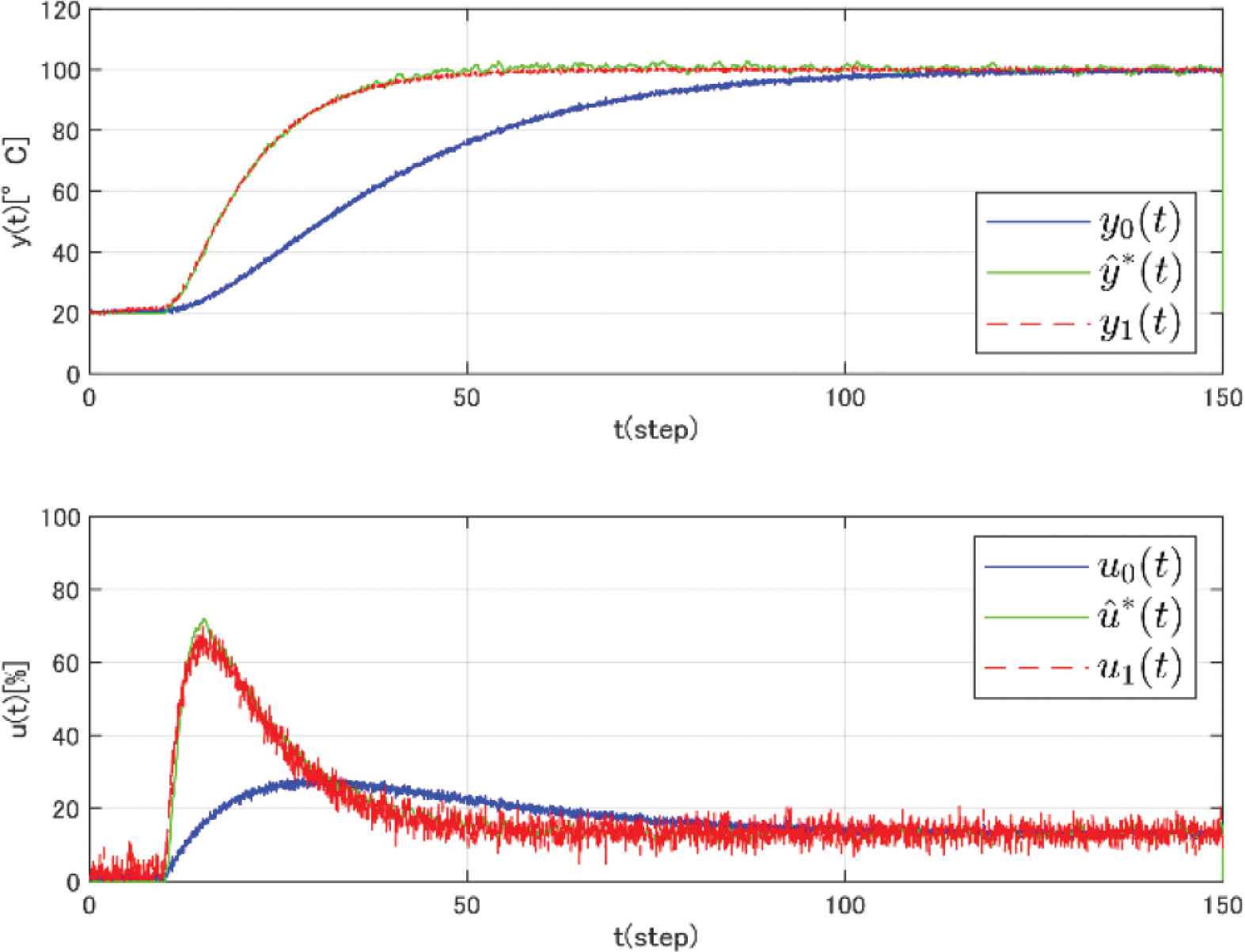
Simulation results by applying the proposed scheme where λ = 0.5.
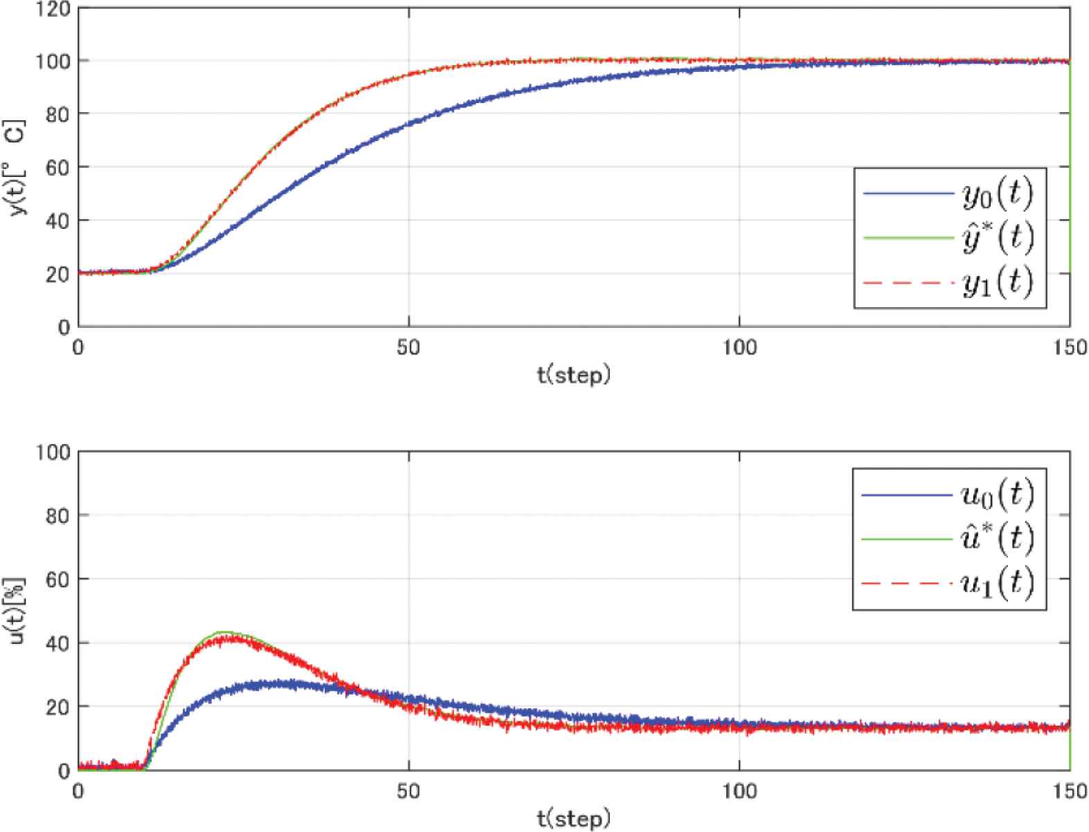
Simulation results by applying the proposed scheme where λ = 5.
Furthermore, it is possible to design a controller that considers the input/output responses because the desired predicted data
5. CONCLUSION
In this paper, the new data-driven control scheme has been proposed to design a 1DOF by considering input response for unknown structure systems. The effectiveness has been numerically verified by the simulation example. It is possible to predict the appropriate amount of input response to correspond the performance of the actuator by predicting the input in advance. In the future, the scheme how to choose λ and the controller design considering the input saturation will be studied.
CONFLICTS OF INTEREST
The authors declare they have no conflicts of interest.
AUTHORS INTRODUCTION
Mr. Yuki Nakatani
 He received his B. Eng. from Hiroshima University in Japan in 2020. He is currently a Master course student in Hiroshima University in Japan.
Dr. Takuya Kinoshita
 He received his B. Eng., M. Eng. and D. Eng. from Hiroshima University in Japan in 2013, 2015 and 2017, respectively. He was postdoctoral fellow of JSPS (Japan Society for the Promotion of Science) in 2017. He is currently an Assistant Professor with the Department of Graduate School of Advanced Science and Engineering, Hiroshima University, Japan. His research interests are performance-driven control.
Prof. Toru Yamamoto
 He received the B. Eng. and M. Eng. degrees from Tokushima University, Tokumshima, Japan, in 1984 and 1987, respectively, and the D. Eng. degree from Osaka University, Osaka, Japan, in 1994. He is currently a Professor with the Graduate School of Advanced Science and Engineering, Hiroshima University, Japan. He was a Visiting Researcher with the Department of Mathematical Engineering and Information Physics, University of Tokyo, Tokyo, Japan, in 1991. He was an Overseas Research Fellow of the Japan Society for Promotion of Science with the University of Alberta for 6 months in 2006. His current research interests are in the area of data-driven control, and process control. He was the recipient of the Commendation for Science and Technology by the Minister of Education, Culture, Sports and Technology in 2009.
REFERENCES
Cite this article
TY  - JOUR
AU  - Yuki Nakatani
AU  - Takuya Kinoshita
AU  - Toru Yamamoto
PY  - 2021
DA  - 2021/10/09
TI  - Design of a Data-Driven Control System based on Reference Model using Predicted Input/Output Responses
JO  - Journal of Robotics, Networking and Artificial Life
SP  - 170
EP  - 174
VL  - 8
IS  - 3
SN  - 2352-6386
UR  - https://doi.org/10.2991/jrnal.k.210922.004
DO  - 10.2991/jrnal.k.210922.004
ID  - Nakatani2021
ER  -