
End-to-End Deep Learning by MCU Implementation: Indoor Localization by Sound Spectrum of Light Fingerprints
- DOI
- 10.2991/jrnal.k.210922.007How to use a DOI?
- Keywords
- Light fingerprint; machine learning; indoor; localization
- Abstract
This paper introduces a low-cost indoor localization system using sound spectrum of light fingerprint. An Artificial Intelligence (AI), algorithm will be implemented in a low-cost Micro-Control Unit (MCU), to perform the localization function. The unique light fingerprints with complex and tiny differences are caused by the different characteristics of the discrete components used in lighting devices. Only sound spectrum of light fingerprint is adopted for the identification of the lighting device to reduce the memory size requirement for implementation in a low-cost MCU. So, the grid search is used to optimize the hyperparameters for the smallest AI model. The system architecture and algorithm development are discussed in this paper, and the experimental results will be present to show the performance of the proposed system.
- Copyright
- © 2021 The Authors. Published by Atlantis Press International B.V.
- Open Access
- This is an open access article distributed under the CC BY-NC 4.0 license (http://creativecommons.org/licenses/by-nc/4.0/).
1. INTRODUCTION
Indoor localization is an issue in may application, such as automated guided vehicle, smart building. The traditional positioning method, Global Positioning System (GPS), is not workable indoors. Due to the infrastructure-less characteristics, several indoor localization methods have been proposed. In other side, how to modularize the localization method is another key point for using the technology in indoor environment.
It is noted that there have been several literatures on this issue. A mobile phone was used to sense the light and convert it to the Received Light Strength (RLS). This RLS would be compared with other RLSs on the map, then the position was located by the similar RLS [1]. According to Hu et al. [1], Liu et al. [2], Zhao et al. [3], the spectrometer can be used to analyze the difference in the spectrum of the ambient light, the light detector resistor can be used as the equipment to sense the light intensity, and a continuous segment of moving position information can be also used to achieve the positioning. Four Light Emitting Diodes (LED) placed on the ceiling were used to transmit the encoded and modulated optical signals with position coordinates, and the signal received from photodiode receiver was analyzed to calculate the positions of the objects [4–6]. In Hamidi-Rad et al. [7], light signals were acquired at high sampling frequency, up to 1 mega-samples/second, and then mapped into the frequency domain by Fast Fourier Transform (FFT). The k-nearest neighbor and Convolutional Neural Net (CNN) classifiers were discussed. The hardware system is comprised of a high-frequency light sensor, Analog-to-Digital Converter (ADC) scope, and Raspberry-PI processor to improve the performance of the classifiers. In Kobayashi [8], the microphone block equipped on the mobile phone was used to sample the light signal sensed by a Photodiode (PD), and then the sampled information was sent to the cloud server through the network. The FFT preprocessing and 1-dimensional CNN were performed on the server, to achieve the classification missions. Hu et al. [1] and Chen et al. [4] used other characteristics for localization, and never mentioned about realization. In Hamidi-Rad et al. [7], a modularized indoor localization system was designed; however, the designed system included an extra high sampling rate ADC. The method proposed in Kobayashi [8] only needed the acoustic frequency spectrum of the light, which means that only lower sampling frequency was required. Notice that all the above proposed localization algorithms were performed in cloud sever. The proposed method in this paper is similar to Kobayashi [8] with extension and modification, and how to realize the method into a module will be detailed.
It should be pointed out that the most studies on the indoor localization focused on the AI algorithm on applications, but few of them pay attention to the modularized realization of the indoor localization. should be revised as “Besides, there are only few literatures on the AI implementation in Micro-Control Unit (MCU) or System on a Chip (SoC) platform. In [9], a chamfering tool diagnostic AI algorithm was developed and installed into a SOC. A smart grape with object shape classification function was proposed and implemented into an MCU in Hung et al. [10]. The experimental results of both researches showed that the end-point machine learning equipment could provide a complete AI function in real time. The modularization will be also detailed in this paper.
2. DATA ACQUISITION
Data acquisition has been an important issue in the machine learning. How to sample useful data and extract feature to train AI models has become a key topic. First, the sampling rate needs to be considered, due to higher sample frequency means higher cost and larger-memory requirement. Next, data preprocess is also necessary to extract the key features. FFT is adopted in this paper to translate sampled data from time domain to frequency domain. After that, some portions of spectrum will be ignored because of less features and reduction of memory and calculation.
2.1. Data Acquisition and Feature Spectrum Extraction
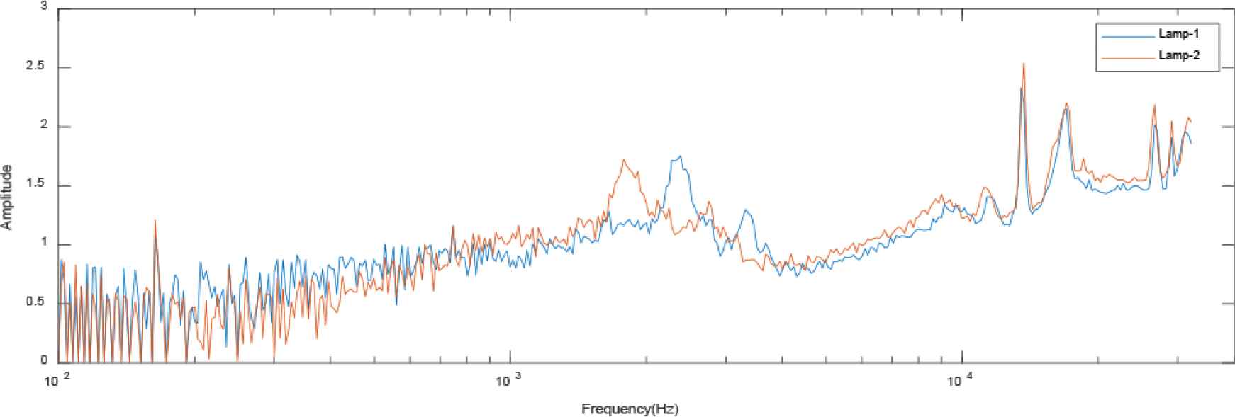
In proposed system, the ADC, build in MCU is used to sample the time domain data. First, higher sampling rate and the larger number of sampling points is selected to confirm the feature frequency. Then, the sampling rate and point will be optimized to suitable for modularization, it means to minimize these two number but keep the feature. The preprocessor is Discrete Fourier Transform (DFT), to present the frequency feature of the sampling data. Note, in most cases, the DFT is performed by FFT library function in development system, and the function also is called in this project. The formula is shown in Equation (1), X[.] and x[.] represent respectively the frequency and time domain data; k and n denotes the k-th point frequency and n-th point sampling data, and N is the totally sampling points. The frequency resolution, Δf, of FFT is as Equation (2), here, fs indicates the sampling rate (frequency). The typical FFT results of two fluorescent lamps are shown in Figures 1 and 2, the 16,384 points time domain data sampled at 65,536 Hz.
The light spectrums of these two fluorescent lamps are different. Obviously, the most features of the spectrum locate at low frequency interval. Note, here is a huge spike at 120 Hz no matter lamp 1 or 2, because fluorescent lights is powered by magnetic ballasts with a frequency of 60 Hz (50 Hz in some country) and lamps flicker with the double frequency. In other word, this phenomenon might not appear if the lamp is LED based. Moreover, the portion less than 150 Hz will not be used in localization. In the other side, there are also some peaks around 32 kHz, this portion near Nyquist frequency is also ignored. Only the spectrum from 150 Hz to 30 kHz is used to machine learning and localization.
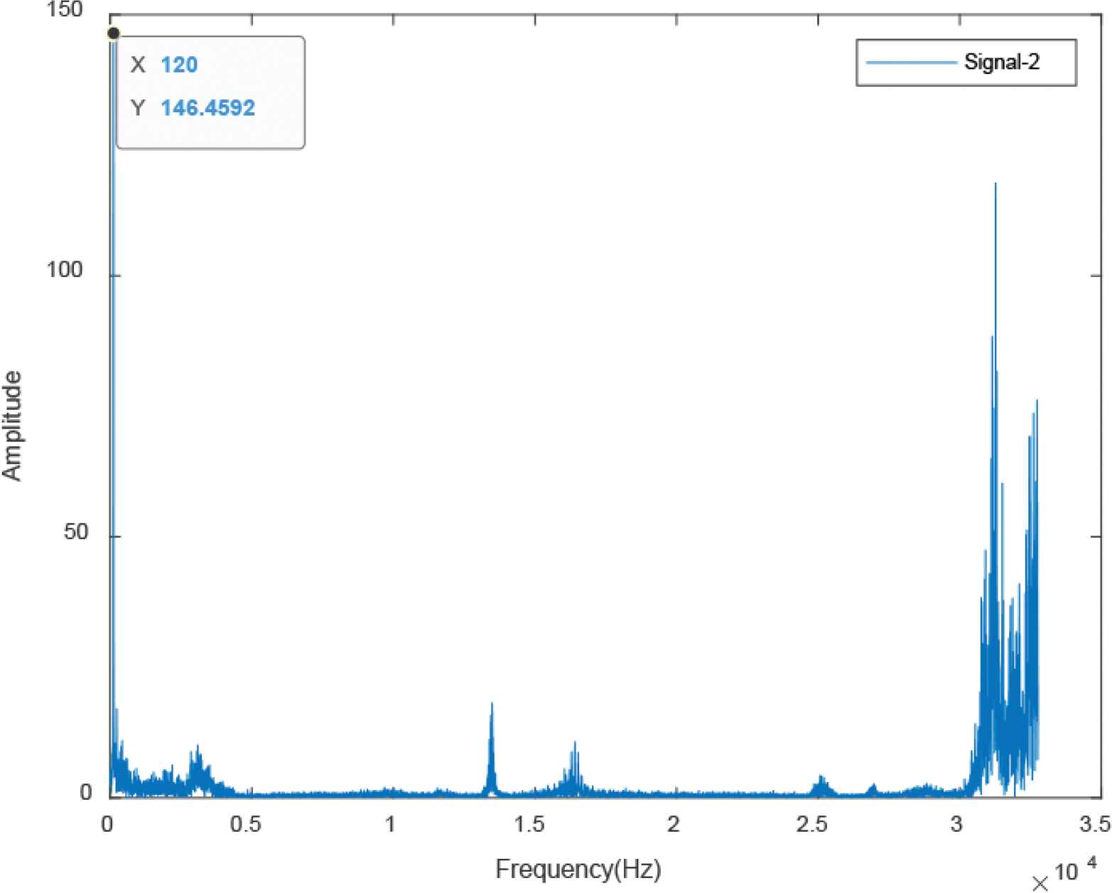
The spectrum of the fluorescent tubes 1.
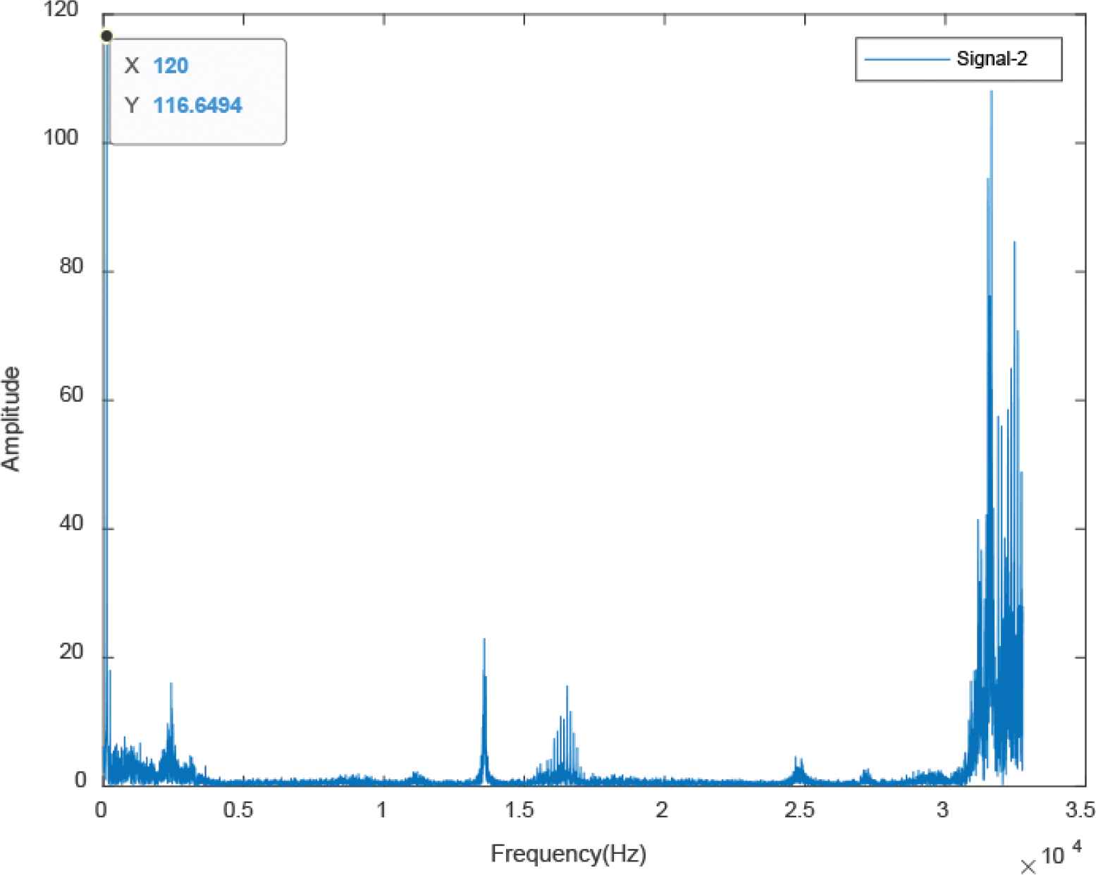
The spectrum of the fluorescent lamp 2.
2.2. Rescaling
For modularization, the artificial intelligence algorithm will be implemented into an MCU, which calculation and memory capabilities are limited. The less node number of input layer the less operation and memory requirement. The reduction of the input nodes but without losing frequency feature is important. As shown in Figures 3 and 4, the low frequency spectrum contains most information, so frequency rescaling equation will be adopted to cover original frequency data to the characteristic vector [4]. The frequency axis will be rescaled to power of Ffactor as shown in Equation (3), and the Ffactor is shown as Equation (4). Here, fmax and fmin indicate the frequency range which is used in machine learning, and NF_target is the target number of reduction. Finally, the amplitude of rescaling spectrum, A[i], is the summation of the amplitude which frequency between two rescaling frequency axis point [Equation (5)].
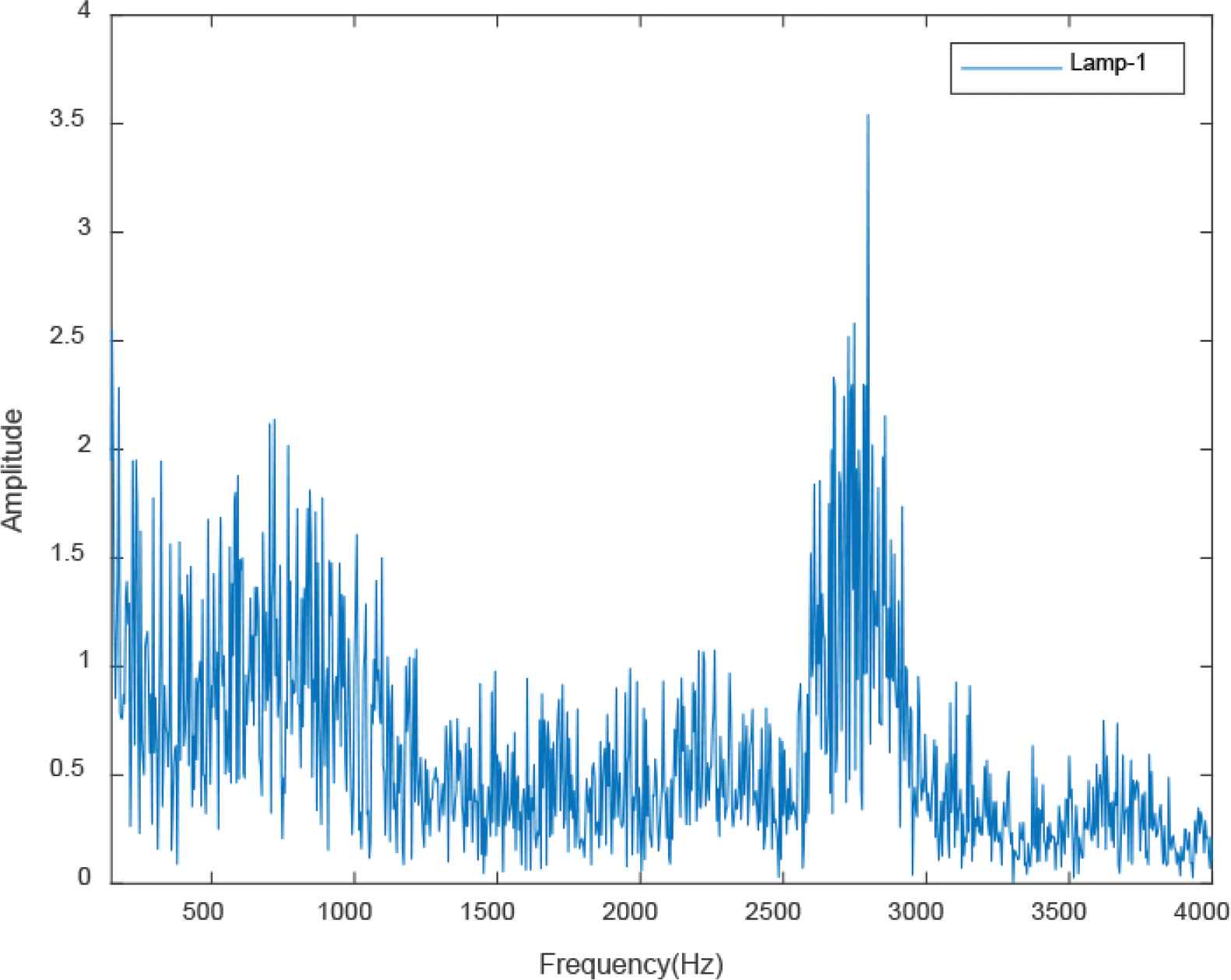
The spectrum of 150 to 4000 Hz for the lamp 1.
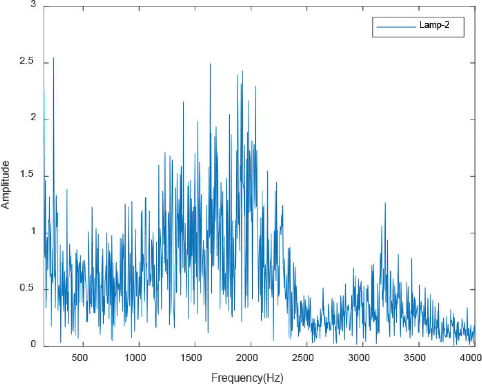
The spectrum of 150 to 30 kHz for the lamp 2.
The rescaling results of frequency information from the two lamps are presented in Figure 5. Here, fmax and fmin are set to 150 and 30 kHz, and rescaling points are 400. The rescaling results keep the original features in low frequency spectrum, and high frequency’s is summed into low resolution form. However, the input data are reduced 75 times, this rescaling processing will reduce the requirement of memory and calculation dramatically. In other words, it is very helpful for modularization in a low-cost MCU.
The rescaling result for the lamp 1 and 2.
3. IDENTIFICATION ALGORITHM AND GRID SEARCH FOR HYPERPARAMETERS
3.1. Identification Algorithm
Convolutional neural net is a popular algorithm for classification due to its ability to learn and extract the features, and less parameter memory and calculation requirement is suitable for modularization [10–13]. 1-D CNN is adopted in this paper due to the resource limitation in a low-cost MCU, no matter memory or calculation speed. The structure and calculation diagram of CNN is shown in Figure 6. The filter Kernel in convolution layer is used to extract certain features from rescaling spectrum, and the full connected layers perform the classification, but the pooling layer is skipped in this application.
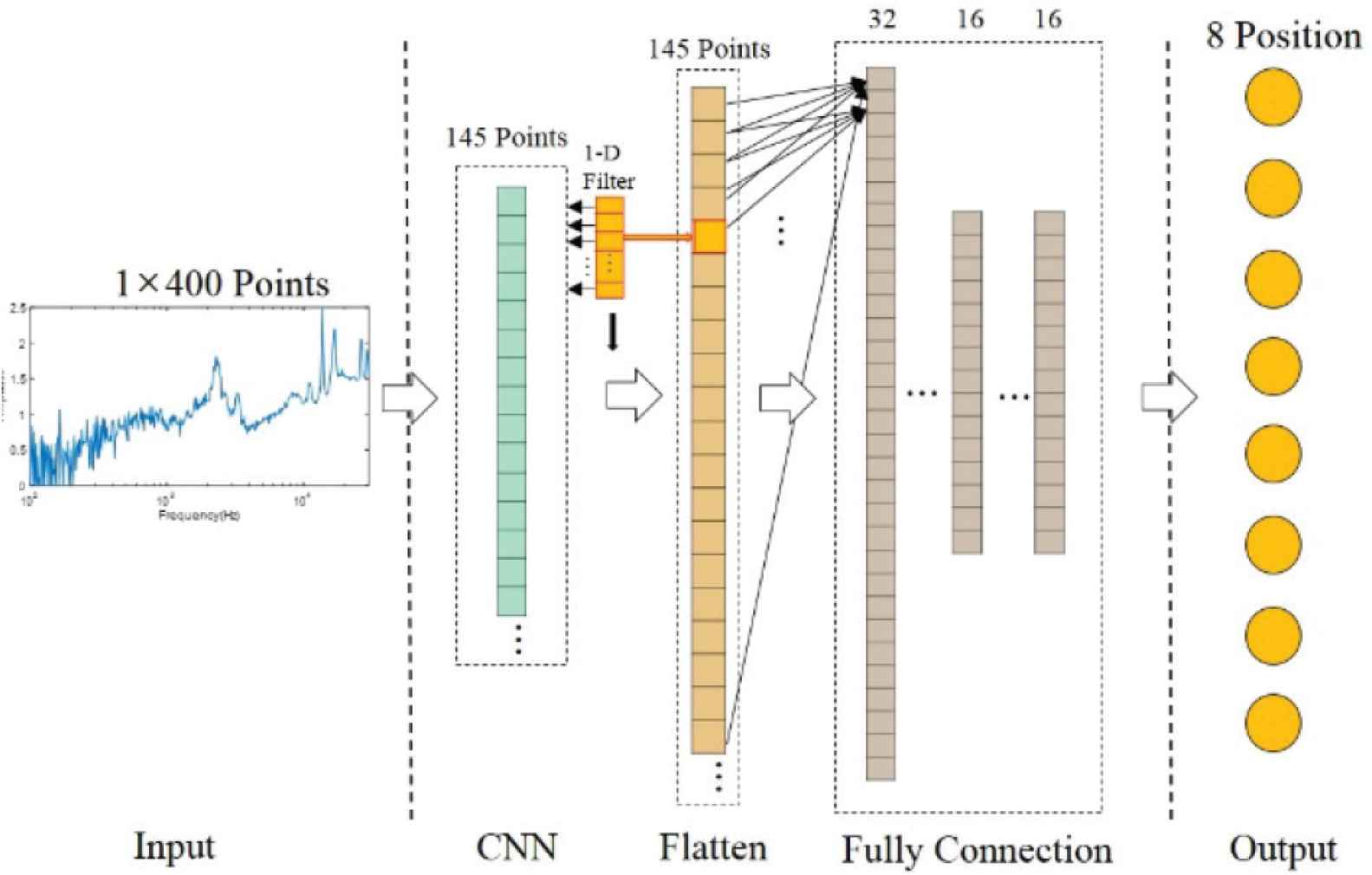
The CNN architecture diagram.
3.2. Grid Search of the Hyperparameter
Grid search is standard skill to get the hyperparameter combination of the highest accuracy [13], such as CNN Filter Kernel number and size. Different from general grid search which only focus on accuracy, the memory size of parameter is more important factor for modularization. The grid search items and the range is expressed in Table 1, and here are totally 240 parameter combination.
| Item | Parameter |
|---|---|
| CNN filter Kernel number | 1, 2 |
| CNN filter size | 2, 4, 8, 16, 32, 64, 128, 256 |
| Activation function of fully connected layer | ReLU, Tanh, Sigmoid |
| Node of fully connected layer | 64, 32, 16, 8, 4 |
The items and parameters of grid search
The proposes localization system is designed for eight lamps position, and 100 averaged rescaling data is collected from each lamp for training. To eliminate random errors caused by initial random weights, every three training results for each parameter combination are averaged. The iteration number set to 1000, and early stopping is adopted to avoid overfitting per training round. The grid search results are sorted by verified accuracy and parameter file size. In the 240 training results for all parameter combination, the top 10 results are shown in Table 2.
| Train. acc. | Train. loss | Verified acc. | Filter Kernel | Filter size | Act. func. | Nodes of fully connected layer | Memory size (kB) |
|---|---|---|---|---|---|---|---|
| 1 | 0.000577 | 1 | 1 | 256 | ReLU | 32/16/16 | 5.96875 |
| 1 | 0.010547 | 1 | 1 | 256 | Tanh | 32/16/16 | 5.96875 |
| 1 | 0.051400 | 1 | 1 | 256 | Sigmoid | 32/16/16 | 5.96875 |
| 1 | 0.010734 | 1 | 1 | 128 | Tanh | 32/16/16 | 9.71875 |
| 1 | 0.048613 | 1 | 1 | 128 | Sigmoid | 32/16/16 | 9.71875 |
| 1 | 0.010579 | 1 | 2 | 256 | Tanh | 32/16/16 | 10.4687 |
| 1 | 0.085243 | 1 | 2 | 256 | Sigmoid | 32/16/16 | 10.4687 |
| 1 | 0.011359 | 1 | 1 | 64 | Tanh | 32/16/16 | 11.5937 |
| 1 | 0.002533 | 1 | 1 | 256 | Tanh | 64/32/32 | 12.9375 |
| 1 | 0.010598 | 1 | 1 | 256 | Sigmoid | 64/32/32 | 12.9375 |
The top ten results grid search
The parameters of CNN model are detailed in Table 3, the parameters are got from the grid search. The settings of fully connected layer number and activation function are 3 and Tanh. The number of output node is eight, its form is likelihood by SoftMAX function.
| Item | Parameter |
|---|---|
| CNN filter Kernel number | 1 |
| CNN filter size | 256 * 1 |
| Activation function of CNN | ReLU |
| Node of fully connected layer 1 | 32 |
| Node of fully connected layer 2 | 16 |
| Node of fully connected layer 3 | 16 |
| Activation function of fully connected layer | Tanh |
| Node number of output layer | 8 |
| Activation function of output layer | SoftMAX |
The parameters of CNN model
4. IMPLEMENTATION
4.1. Hardware
The main target in this paper is a low-cost indoor localization module. The specification of components used in the proposed system is listed in Table 4. The RX65N MCU, provided by Renesas Electronic Corporation, is used to implement the proposed algorithm. The build-in 2 MB of read-only memory, and 640 KB random access memory, are enough to install the optimized AI model, and the high-speed operation with 32-bit floating point could support the calculation requirement like the FFT and matrix multiply in ANN.
| Type | Specification |
|---|---|
| MCU | RX65N R5F565NEDDFP |
| Amplifier | OPA1612A |
| Charge pump | TPS60403DBVR |
| Photodiode | S6967 |
The hardware specification
And the operational amplifier, OPA1612A, is selected to its low noise amplification function, 1.1 nV/(Hz)1/2. The feature spectrum could be kept after the amplifier circuit. And its input voltage range is wide from ±2.25 to ±18 V; its positive powered from the Vcc, shared the power source with MCU. Besides, negative provide from the charge pump. The PD used in the system is S6967. It can sense the wavelength range from 320 to 1060 nm, cover the range from 400 to 800 nm, which range is used in the household lighting equipment. Moreover, the bandwidth of the S6967 is higher to 1 MHz to catch the feature in high frequency.
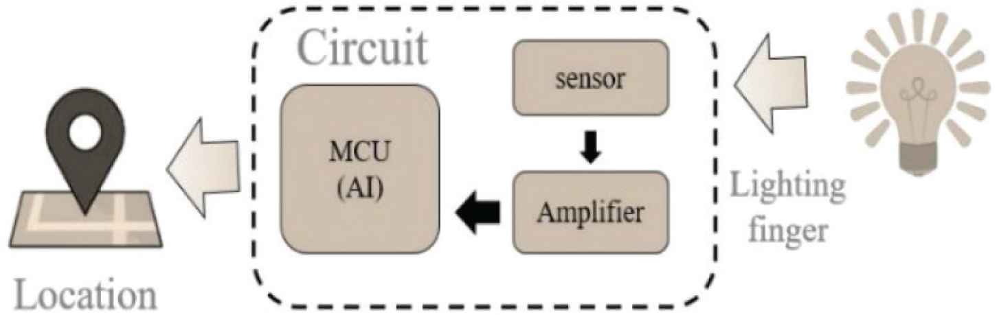
The proposed system is shown in Figure 7, it includes a sensor circuit, amplifier block and MCU. The sensor circuit consists of a photodiode and resister, and the amplifier block is implemented with operational amplifier to perform the gain and filter functions. The system hardware is present as Figure 8. Note, the hardware is only for experimentation but not size-optimization yet.
The spectrum of the fluorescent tubes.
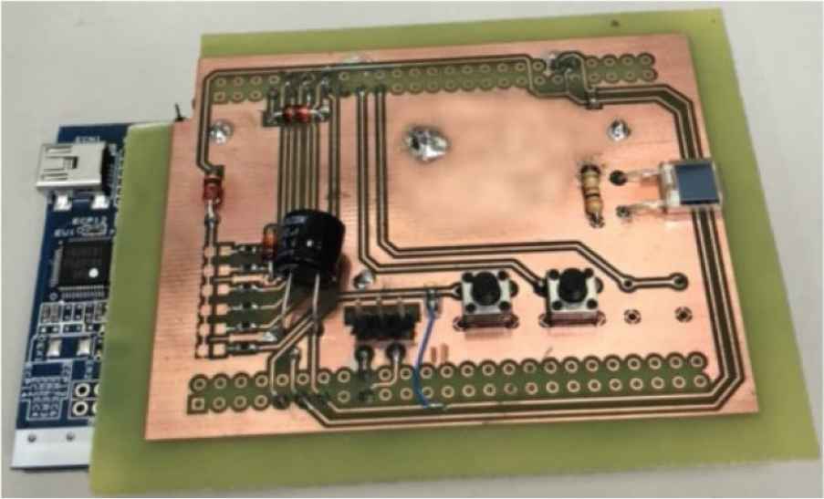
The photo of proposed hardware.
The signal processing flow is indicated in Figure 9, moreover, the processing time of every sub processing block is also shown. The longest duration is data acquisition. However, it is necessary, because the data is sampled three times, and there is 16,384 points sampled at 65,536 Hz every time. The transfer time from time domain data to frequency domain may be shorted by faster MCU. And before localization AI algorithm, the rescaling FFT results of three samples are averaged.
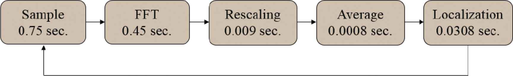
The signal processing flow is dedicated.
4.2. From AI Model to MCU Code
To run machine learning models on microcontroller, MCU, is important in this research, and how to translate the AI model to C code will be the key. “TensorFlow Lite for Microcontrollers” is designed to run a TensorFlow AI model on a microcontroller [14], and it is a useful tool. However, the MCU platforms and AI models supported by this tool is limited, nor includes the RX65N MCU what is adopted in the proposed system. The alternative is the other tool, e-AI Translator, provided by the MCU provider, Renesas, for its productions [15]. It can translate the AI models (.pb or checkpoint) in the C-language code for the Renesas MCU. Moreover, the tool also performs the calculations of the memory size and amount of calculation required by the machine learning model are also estimated, and the multiply and accumulation number calculation when the AI model operates.
5. EXPERIMENT
5.1. Setup
The experiment was performed in the EN303 room on third floor of the Engineering sixth hall, National Yunlin University of Science and Technology, as shown in Figure 10. The proposed module is located about 1.7 m below lamps, and the numbers in Figure 10 denote the lamps as also in Figure 11. The floor plan is revealed in Figure 11, which also includes the location of lamps, the distance between each lamps and from lamp to hall. Note, the ‘X’ marks indicate the location when testing is below the lamp, and the ‘+’ marks shows the position when testing is not below the lamps.
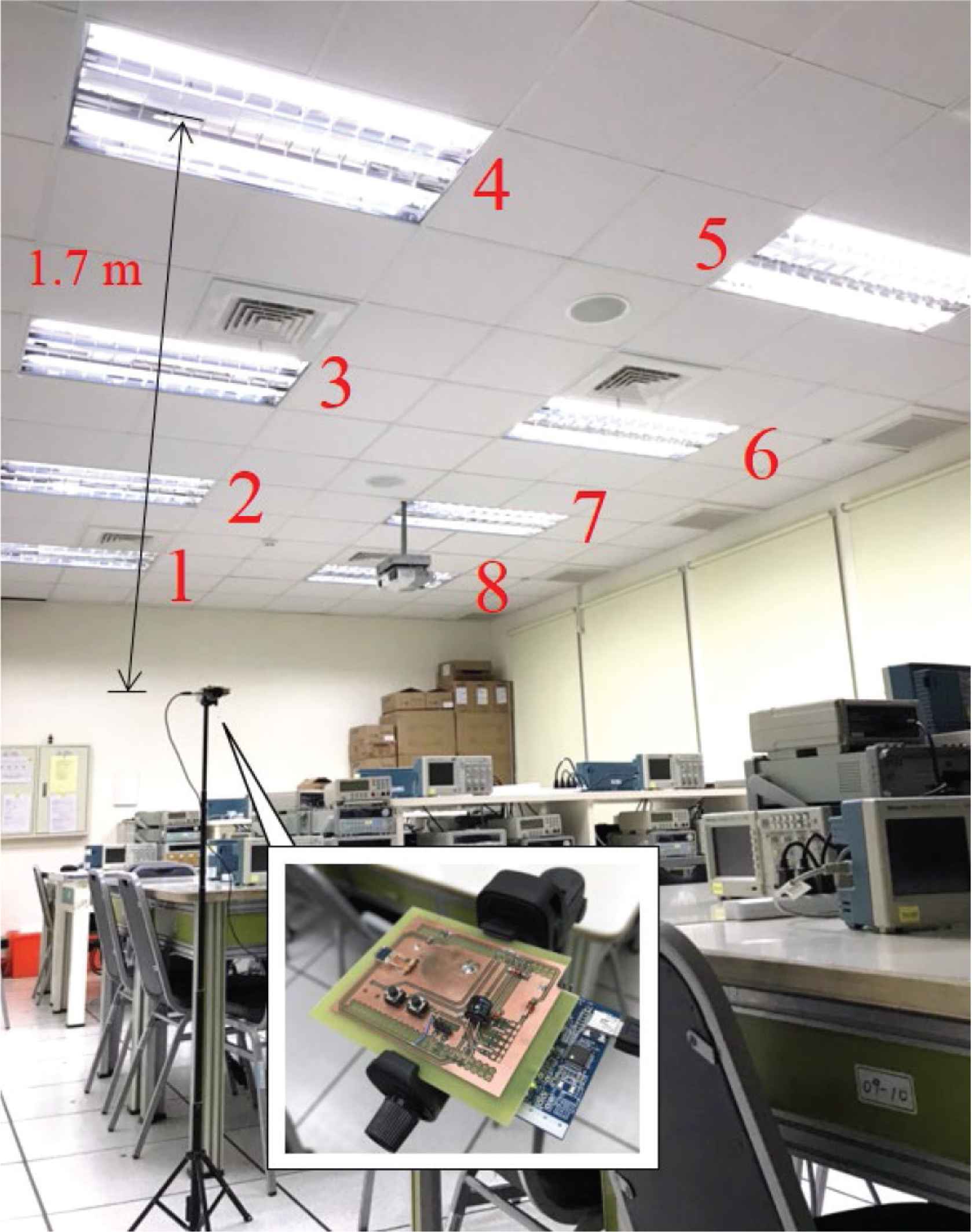
Experiment in the EN303 room.
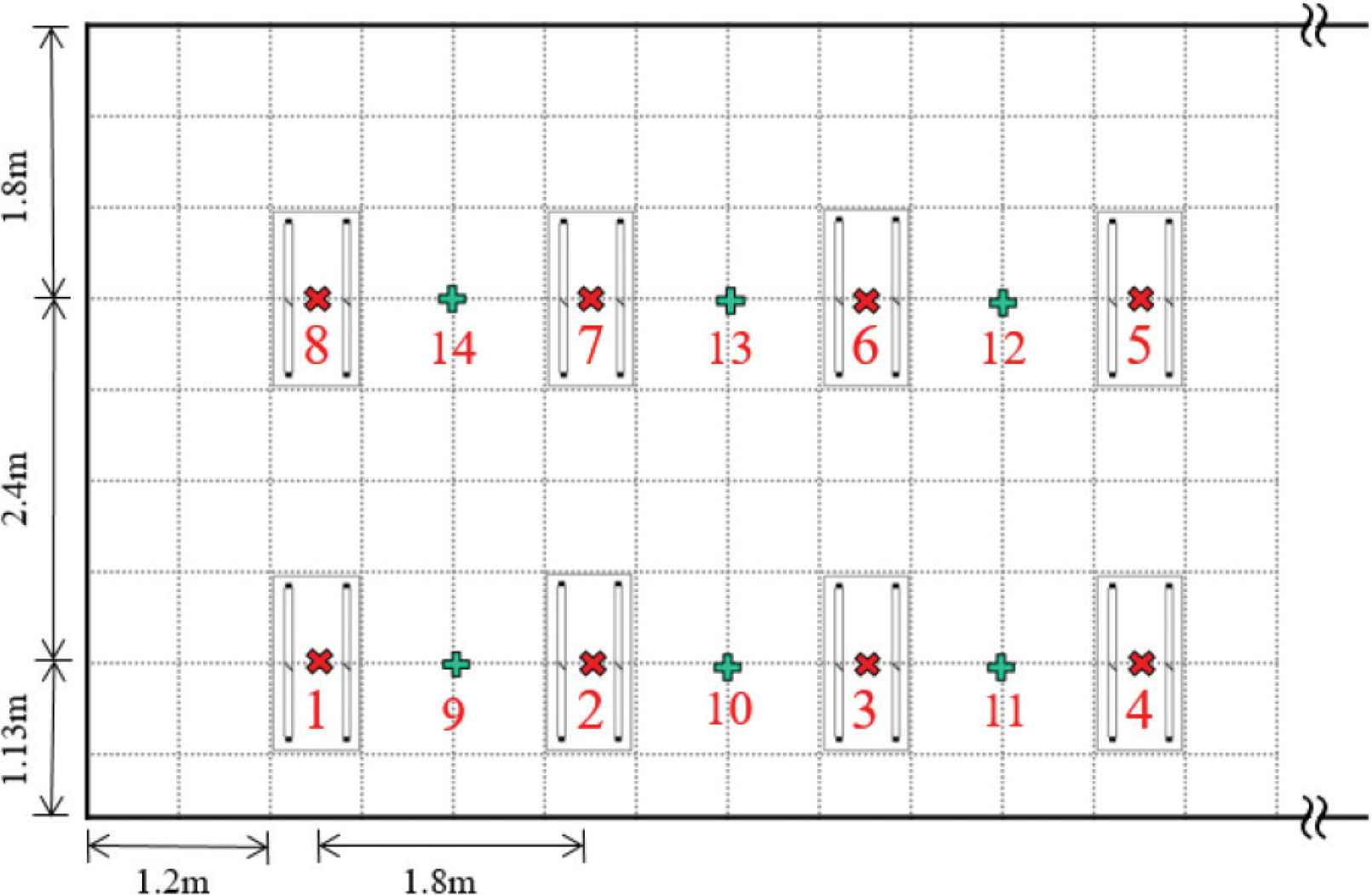
Floor Experiment in the EN303 room.
5.2. Results
The estimated likelihoods of classification are shown in Table 5, the proposed module is placed below the lamps which are marked by ‘X’ turn-by-turn. The number in the table indicates the most likelihood lamp number, and the number in the parentheses shows the estimated likelihood. The experiment ran 10 turns, and every ‘X’ point is tested every turn. The localization accuracy performed 100%. The least likelihood in the table locates at lamp 4 in the turn 8, however the likelihood still achieved 75.8%, it demonstrated the localization is correct.
| Turn | Lamp1 | Lamp2 | Lamp3 | Lamp4 | Lamp5 | Lamp6 | Lamp7 | Lamp8 |
|---|---|---|---|---|---|---|---|---|
| 1 | 1 (98.8) | 2 (98.9) | 3 (98.9) | 4 (97.6) | 5 (96.2) | 6 (98.9) | 7 (98.4) | 8 (99.1) |
| 2 | 1 (98.6) | 2 (98.9) | 3 (97.2) | 4 (97.6) | 5 (98.1) | 6 (98.8) | 7 (96.5) | 8 (99.1) |
| 3 | 1 (98.2) | 2 (98.9) | 3 (98.2) | 4 (95.3) | 5 (98.2) | 6 (98.8) | 7 (98.5) | 8 (99.0) |
| 4 | 1 (98.5) | 2 (98.9) | 3 (98.6) | 4 (93.1) | 5 (96.9) | 6 (98.9) | 7 (98.3) | 8 (99.1) |
| 5 | 1 (97.4) | 2 (99.0) | 3 (91.3) | 4 (95.1) | 5 (97.3) | 6 (98.9) | 7 (98.5) | 8 (98.9) |
| 6 | 1 (98.9) | 2 (99.0) | 3 (98.9) | 4 (96.4) | 5 (98.2) | 6 (98.8) | 7 (98.5) | 8 (99.1) |
| 7 | 1 (98.6) | 2 (99.0) | 3 (98.5) | 4 (94.2) | 5 (98.2) | 6 (98.9) | 7 (98.5) | 8 (99.1) |
| 8 | 1 (98.8) | 2 (98.9) | 3 (96.4) | 4 (75.8) | 5 (98.2) | 6 (98.9) | 7 (98.5) | 8 (99.0) |
| 9 | 1 (98.7) | 2 (98.9) | 3 (98.5) | 4 (93.9) | 5 (98.0) | 6 (98.8) | 7 (98.5) | 8 (99.1) |
| 10 | 1 (98.9) | 2 (98.9) | 3 (95.0) | 4 (90.8) | 5 (98.1) | 6 (98.8) | 7 (98.3) | 8 (98.8) |
Likelihood of classification of the turns
Table 6 presents an interesting estimation results, the average likelihood of 10 turns is expressed by percentage, when the proposed module is placed at mark ‘+’ position. The two adjacent likelihoods shown in bold are expected to be highest two number, because the testing position is located between the two lamps indicated in the first line of table. However, the expectation was correct such as position 9, 11 and 13, but incorrect for other points. The reason should be that the sample located the position 9–14 never be adopted for AI model training and the estimated likelihood is not the interpolation of any two training points. The future work is to adopt such position sample to machine learning to evaluate the localization effect if not sampled below the lighting source.
| Pos. | Lamp1 | Lamp2 | Lamp3 | Lamp4 | Lamp5 | Lamp6 | Lamp7 | Lamp8 |
|---|---|---|---|---|---|---|---|---|
| 9 | 28.333 | 26.879 | 1.589 | 3.464 | 36.366 | 1.612 | 1.506 | 0.251 |
| 10 | 0.113 | 80.002 | 7.090 | 0.288 | 0.033 | 10.378 | 1.790 | 0.306 |
| 11 | 0.138 | 0.054 | 38.109 | 60.799 | 0.490 | 0.056 | 0.300 | 0.055 |
| 12 | 0.033 | 0.652 | 0.017 | 0.123 | 0.509 | 97.521 | 0.863 | 0.283 |
| 13 | 0.011 | 1.321 | 0.046 | 0.267 | 0.757 | 22.136 | 74.460 | 1.001 |
| 14 | 0.080 | 0.034 | 0.004 | 0.193 | 0.657 | 0.976 | 1.443 | 96.620 |
Likelihood estimation between two lamps
6. CONCLUSION
In this paper, a low-cost indoor localization system using sound spectrum of light fingerprint is proposed. To implement this light fingerprint-based localization indoor mobile equipment, modularization is the key consideration. So, the memory and calculation of the selected MCU are limited by cost and size. A simplified 1-D CNN is performed to classify the lamps, and the rescaling frequency features only between 100 Hz to 30 kHz are used in classification. Herein, the hyperparameter of the machine learning model is optimized to find the highest-accuracy and smallest-size model, after grid search. The experiment results show that the system could be implemented in a lost-cost MCU with few components. The on-line tests present the localization accuracy achieve 100% when the proposed device located below the lamps. However, not as expected, when testing position locates between lamps, the likelihood is not an interpolation of the nearest two lamps. It may be the future works of this topic.
CONFLICTS OF INTEREST
The authors declare they have no conflicts of interest.
ACKNOWLEDGMENTS
The part of this work was financially supported by Ministry of Science and Technology, Taiwan, under contract MOST 109-2218-E-150-002-, 109-2221-E-224-023-, 108-2221-E-224-045- and 108-2218-E-150-004-.
AUTHORS INTRODUCTION
Prof. Chung-Wen Hung
 He received the PhD degree in Electrical Engineering from National Taiwan University in 2006. Currently, he is a professor in National Yunlin University of Science & Technology. His research interests include IoT, IIoT, Power Electronics, Motor Control, and AI Application.
Prof. Hiroyuki Kobayashi
 He received PhD degree in Engineering from Tokyo Institute of Technology, Japan in 2003. He worked at Keio University and Tokyo University of Technology, then moved to Osaka Institute of Technology in 2006, where he is now working as a professor. His interests include mobile robots localization, AI and IoT applications.
Mr. Jun-Rong Wu
 He received his B.S. in Electrical Engineering from Southern Taiwan University of Science and Technology. Since September 2019, he is a graduate student at the National Yunlin University of Science and Technology. His research interests include Data Science and Artificial Intelligence Algorithms in automatic systems.
Prof. Chau-Chung Song
 He received the PhD degree in Electrical and Control Engineering from National Chiao Tung University in 2001 at Taiwan. He is currently a distinguished professor in Department of Aeronautical Engineering, National Formosa University. His research interests include the integration application of networking information system, the UAV technology, and the cloud network and Cyber-Physical System (CPS).
REFERENCES
Cite this article
TY  - JOUR
AU  - Chung-Wen Hung
AU  - Hiroyuki Kobayashi
AU  - Jun-Rong Wu
AU  - Chau-Chung Song
PY  - 2021
DA  - 2021/10/09
TI  - End-to-End Deep Learning by MCU Implementation: Indoor Localization by Sound Spectrum of Light Fingerprints
JO  - Journal of Robotics, Networking and Artificial Life
SP  - 186
EP  - 192
VL  - 8
IS  - 3
SN  - 2352-6386
UR  - https://doi.org/10.2991/jrnal.k.210922.007
DO  - 10.2991/jrnal.k.210922.007
ID  - Hung2021
ER  -