
Design System of Cell Type Assembly Machine with Dual Arms Robot by GA
- DOI
- 10.2991/jrnal.2018.5.1.12How to use a DOI?
- Keywords
- genetic algorithm; Unit arrangement decision; Dual arm robot; Assembly machine
- Abstract
The purpose of this research is to develop a system named DELUGA which automatically decides by genetic algorithm (GA) where to place a lot of assembled parts, jigs and robot hands in the workstation when designing a cell type assembly machine with a dual arms robot. In DELUGA, since the left and right robot arms simultaneously perform assembly work, adopt the concept of waiting time to prevent interference between the left and right arms. The cycle time from assembly to completion is used as fitness, GA operation is performed, and better arrangement is decided.
- Copyright
- Copyright © 2018, the Authors. Published by Atlantis Press.
- Open Access
- This is an open access article under the CC BY-NC license (http://creativecommons.org/licences/by-nc/4.0/).
1. Introduction
In this research, we develop the system called DEciding Locations of Units by Genetic Algorithm (DELUGA) for determining the units arrangement of cell type assembly machines[1] with a dual arms robot by Genetic algorithm (GA). The unit includes dual arm robot’s hands, parts trays and jigs. Generally, the units arrangement which is one of the components of the workstation was decided by the production engineer. We aim to improve the design and production efficiency by automating the units arrangement determination.
2. Cell type assembly machine
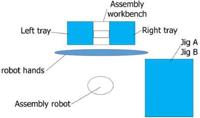
As shown in Fig. 1, the cell type assembly machine of this research consists of an assembly dual arms robot which is located in the center of the assembly machine, an assembly workbench in front of the robot and the units located around the robot.
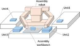
Cell type assembly machine
2.1. Assembly process
The assembly machine of this study uses a dual arm robot, that is, each arm chucks a unit necessary for an assembly work, carries it to the assembly workbench and assembles parts. In this research, we define three positions existing on the movement path of the robot arm, approach 1, approach 2 and chuck position. Each definitions is as follows.
Chuck position: position to put or grasp the unit
Approach 1: position upward away from the chuck position
Approach 2: position further upward than Approach 1
The arm passes from approach 2 through approach 1 and arrives at the chuck position. When the arm leaves the unit, it performs the reverse operation (see Fig. 2).With this definition, the assembly time calculations can be formulated.
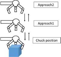
Movement of arm
3. DELUGA
DELUGA is the system that determines the arrangement of each unit with a high efficiency by using GA when a cell type part assembly machine is designing. DELUGA consists of two modules, the conditions module and GA module (Fig. 3). The conditions module reads the placement possible area of the unit and work data, divides the placement possible area, and sets various parameters required for GA. GA module decides the arrangement place of the unit by GA, determines the arrangement of parts in the parts tray which is one of the units by a full search method, evaluates the total working time, and shows the coordinates of the arrangement place of each unit and the output of the acquired arrangement image.
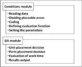
System construction of DELUGA
3.1. Condition creation module
The conditions module is as follows.
Step 1: Read work data of parts assembly, placement possible area, parts arrangement data and create their database
Step 2: Divide placement possible area into a lattice shape to create placement possible place
Step 3: Carry out genes coding
Step 4: Define the fitness function
Step 5: Determine various parameters
3.2. GA module
The process flowchart of the GA module is shown in Fig. 4.
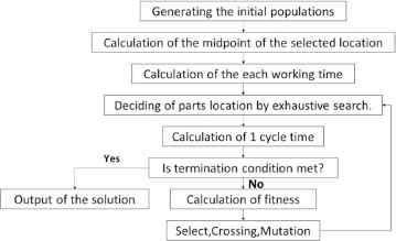
Flowchart of GA module
This detailed process is described below.
Step 1: Generate an initial population
Step 2: Calculate the arrangement coordinates of each unit
Step 3: Determine part placement inside a parts tray by full search method
Step 4: Calculate the time taken for each work
Step 5: Calculate the cycle time of each individual in order not to collide with both arms
Step 6: Calculate fitness
Step 7: Give selection, crossover and mutation
Step 8: Judge whether the termination condition is satisfied or not. If it is satisfied, go to Step 10
Step 9: Give Step 4 to new individuals
Step 10: The unit arrangement of individuals with the smallest cycle time is adopted as the optimal arrangement and output as a solution
4. Application example of DELUGA
The example cell type assembly machine with dual arm robot consists of the units, the left parts tray, the right parts tray, the left parallel hand, the left three nail hand, the right parallel hand, the right four nail hand, the jig A, the jig B. The goal of DELUGA is to decide the better layout of the units. The layout image of the machine is shown in Fig. 5.
Units layout
4.1. System comparison
We compared DELUGA with the following two systems.
- ∙
System that determines unit arrangement only by reinforcement learning
- ∙
System that determines unit arrangement only by GA
The above two systems cannot find the parts layout in the tray. On the contrary, DELUGA can determines the arrangement of parts in the tray.
Fig. 6 is the left and right parts tray. Each number means each part. DELUGA decides the part arrangement in the tray by full search as follows.
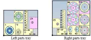
Parts trays
As shown in Fig. 7, we divide the parts in left and right trays into two groups and three groups. Left tray has Group A and Group B, and right tray has Group C, Group D and Group E. Group A has 6 arrangement patterns. Group B to E also have arrangement patterns. Also, we consider arrangements in which Group A and Group B are rearranged, and Group C, Group D and Group E are rearranged. The number of each pattern is shown in Table 3.
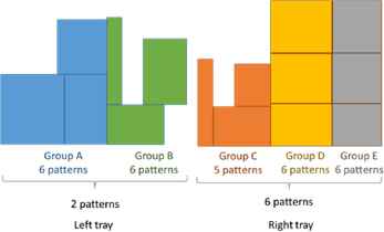
Arrangement pattern of parts
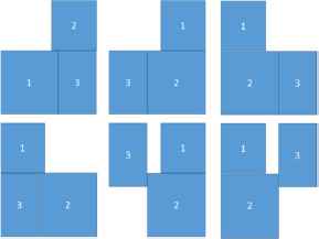
Arrangement of group A
Table 1 shows 6 × 6 × 2 = 72 patterns in the left tray and 5 × 6 × 6 × 6 = 1080 patterns in the right tray.
| Group A | 6 |
| Group B | 6 |
| Sorting A and B | 2 |
| Group C | 5 |
| Group D | 6 |
| Group E | 6 |
| Sorting C, D and E | 6 |
| All patterns | 77,760 |
Number of patterns
That means 72 × 1,080 = 77,760 patterns exist.
4.2. Arrangement determination method
DELUGA calculated 77,760 pattern cycle times of parts arrangement in the tray for each individual during GA operations and the parts arrangement in the tray with the smallest cycle time among them is adopted.
4.3. Details of placement possible area
Table 2 shows the detailed data for the possible placement areas of each unit.
| Unit | x1 | y1 | z1 | x2 | y2 | z2 |
|---|---|---|---|---|---|---|
| Left tray | 1,811.5 | 1,760 | 740 | 1,918.5 | 1,804.5 | 740 |
| Right tray | 2,522 | 1,806.5 | 740 | 2,628 | 1,807.5 | 740 |
| Left parallel hand | 1,280 | 1,480 | 629 | 2,320 | 1,480 | 629 |
| Left three claw hand | 1,280 | 1,480 | 629 | 2,320 | 1,480 | 629 |
| Right parallel hand | 2,100 | 1,480 | 629 | 3,140 | 1,480 | 629 |
| Right four claw hand | 2,100 | 1,480 | 629 | 3,140 | 1,480 | 629 |
| Jig A | 3,034 | 83 | 740 | 3,656 | 1,117 | 740 |
| Jig B | 3,034 | 83 | 740 | 3,656 | 1,117 | 740 |
Placement area of each unit
Table 3 shows the coordinates of the dual arm robot. All units of the label values are mm.
| x | y | z | |
|---|---|---|---|
| Dual arm Robot | 2,210 | 915 | 740 |
Coordinates of dual arm robot
5. Simulation results
We acquired the simulation results as follows.
- ∙
Minimum working time: Smallest working time in each simulation
- ∙
Average working time: average of 100 hours simulation work time
- ∙
Plane drawing of unit arrangement: plan view of arrangement of each unit whose working time is the smallest
The minimum cycle time and the average cycle time of 100 simulations are summarized in Table 4. Acquired unit layouts are shown in Fig. 9, Fig. 10 and Fig. 11. From the Table 4, DELUGA has the shortest cycle time compared with other two systems[2].
| Reinforcement learning | GA | DELUGA | |
|---|---|---|---|
| Minimum time | 237.41 | 237.25 | 234.38 |
| Average time | 237.68 | 237.26 | 234.89 |
Simulation results comparison (seconds)
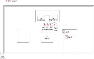
Layout of DELUGA
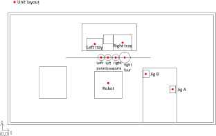
Layout of GA
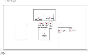
Layout of Reinforcement learning
6. Conclusions
DELUGA is the system that aims the improvement of design and production efficiency by automating the unit arrangement determinations of cell type assembly machine by GA. Compared DELUGA with a dual arm robot system with using reinforcement learning and the system using only GA, we were able to obtain the unit arrangement more efficient than the two systems.
References
Cite this article
TY  - JOUR
AU  - Hidehiko Yamamoto
AU  - Keita Honda
AU  - Takayoshi Yamada
PY  - 2018
DA  - 2018/06/30
TI  - Design System of Cell Type Assembly Machine with Dual Arms Robot by GA
JO  - Journal of Robotics, Networking and Artificial Life
SP  - 52
EP  - 55
VL  - 5
IS  - 1
SN  - 2352-6386
UR  - https://doi.org/10.2991/jrnal.2018.5.1.12
DO  - 10.2991/jrnal.2018.5.1.12
ID  - Yamamoto2018
ER  -