
Dual-stage Release of Ketoprofen from Electrosprayed Core–Shell Hybrid Polyvinyl Pyrrolidone/Ethyl Cellulose Nanoparticles
- DOI
- 10.2991/mathi.k.200825.001How to use a DOI?
- Keywords
- Electrospraying; core–shell nanoparticles; dual-stage release; polymeric nanohybrids
- Abstract
Dual-stage release, consisting of a first fast release for eliminating the uncomfortable symptoms and a later sustained release for a long time period for reducing the administration times, is highly welcomed by the patients. In the present investigation, a new type of core-shell Electrosprayed Nanoparticles (ENPs) were developed for providing a dual-stage controlled release profile of Ketoprofen (KET). A coaxial electrospraying process was explored to prepare the core–shell particles in a directly and straightforward manner. The resultant ENPs were tested in terms of morphology and inner structure, physical state and compatibility between KET and the core matrix of ethyl cellulose, between KET and the shell matrix of polyvinyl pyrrolidone, and the dual-stage controlled release performances. The results from scanning electron microscopy and transmission electron microscope observations demonstrated that the core–shell polymeric nanohybrids had a round morphology with an average diameter of 570 ± 120 nm, and a clear core–shell structure with an estimated shell thickness of 70 nm. KET presented in the ENPs in an amorphous state thanks to the fine compatibility of the hybrid components, as verified by X-ray diffraction and fourier transform infrared spectroscopy (FTIR) tests. In vitro dissolution tests exhibited that the ENPs were able to provide a designed dual-stage controlled release profile with an amount of 45.1 ± 4.5% for the first stage.
- Copyright
- © 2020 The Authors. Published by Atlantis Press B.V.
- Open Access
- This is an open access article distributed under the CC BY-NC 4.0 license (http://creativecommons.org/licenses/by-nc/4.0/).
1. INTRODUCTION
More and more useful drug controlled release profiles have been reported in literature for potential applications of “efficacious, safe and convenient” drug delivery [1–9]. These profiles include immediate release, pulsatile release, delayed release, sustained release, zero-order kinetic release, dual-stage release, and multiple-phase release in terms of the drug release rate and initiating time [10–17]. Among these profiles, dual-stage release is composed of a first rapid release for quickly eliminating the uncomfortable symptoms (such as ache, fever and depression) and a later sustained release for a long time period to considerably reduce the administration times [18–21]. This controlled release profile holds the advantages of both pulsatile release and sustained release, and thus has a high patient compliance.
The traditional pharmaceutical techniques for creating dual-stage release dosage forms are often composed of multiple steps, time-consuming and the products having a high variations in term of controlled release performances. Nanotechnologies, being able to manipulate the components, compositions and also the spatial distributions of active pharmaceutical ingredients, can provided a wide variety of advanced strategies to fulfill the requests in a facile and robust manner. For example, electrospun nanofibers have been reported to furnish dual-stage release profiles through several strategies [21]. One strategy is to prepare blends composed of several polymeric matrices with different properties [22–24]. Another strategy is the deposition and collection of medicated nanofibers through a layer-by-layer manner, in which the outer layer is designed for rapid initial release and the inner core layer is conceived to provide a sustained release. The third strategy is to encapsulate nanoparticles providing drug sustained release into electrospun nanofibers consisting of drug and hydrophilic polymers. And the fourth strategy is to take advantages of the core-sheath structure of electrospun nanofibers, i.e. the sheath section and core section are engineered to provide the first pulsatile and the later sustained release, respectively [14,21].
Similarly, to the coaxial electrospinning, coaxial electrospraying is another electrohydrodynamic atomization method that are frequently exploited to create core–shell nanostructures [25–28]. The differences mainly lie in the mechanism of working processes (splitting for electrospraying and bending and whipping for electrospinning) and the formats of final solid products (particles for electrospraying and fibers for electrospinning). Being inspired by coaxial electrospinning and core-sheath nanofibers, it is hypothesize that coaxial electrospraying and the related core–shell nanoparticles may play their roles in developing new sorts of dual-stage release dosage forms.
In this study, a coaxial electrospraying process was carried out to directly prepare a kind of core–shell particles. With Ketoprofen (KET) as a model active pharmaceutical ingredient, Ethyl Cellulose (EC) and Polyvinyl Pyrrolidone (PVP) as the core and shell polymeric matrics, respectively, a new type of Core–Shell Nanoparticles (ENPs) were generated using the coaxial electrospraying process. Both EC and PVP are common pharmaceutical polymeric excipients. PVP is easy to dissolve in water and is frequently utilized to enhance the fast dissolution of poorly water-soluble drugs, whereas EC is insoluble in water and thus suitable for providing drug sustained release profile [23,24].
2. MATERIALS AND METHODS
2.1. Materials
Ketoprofen (with >98% purity) was kindly provided by Heng-Rui Pharmaceutical Company (Nanjing, China). Polyvinylpyrrolidone K10 (PVP K10, Mw = 8000 g/mol) and ethyl cellulose (EC) were supplied by Shanghai Hao-Sheng Bioengineering Company (Shanghai, China). All the organic solvents were obtained from Merck (Shanghai, China). All other chemicals were analytical grade and water was double distilled before use.
2.2. Preparation
2.2.1. Working solutions
All the solutions were prepared using a mixture solvent of ethanol and dichloromethane with a volume ratio of 6:4. PVP–KET co-dissolving solution was prepared by placing 15.0 g PVP and 2.0 g KET into 100 mL solvent mixture. EC–KET solution was composed of 10.0 g EC and 3.0 g KET in 100 mL solvent mixture.
2.2.2. Apparatus & experimental parameters
For electrospraying, the solutions were loaded into two 10 mL syringes, which were fixed on two fluid drivers. A home-made concentric spraying head was utilized to carry out all the preparation. Electrosprayed Nanoparticles (ENPs) were collected on the aluminum foil collector set at a distance of 20 cm from the nozzle of spraying head. Finally, all ENPs were carefully peeled off from the collector and placed into a desiccator. All the electrospraying experiments were performed at room temperature. Other experimental parameters are included in Table 1.
| No. | Process | Applied voltage (kV) | Core fluid | Shell fluid | Structure | Drug loading (wt%) | ||
|---|---|---|---|---|---|---|---|---|
| Flow rate (mL/h) | Drug con. (w/v%) | Flow rate (mL/h) | Drug con. (w/v%) | |||||
| P1 | Single-fluid | 16 | — | — | 1.0 | 2.0 | Monolithic | 11.8 |
| P2 | Single-fluid | 16 | 1.0 | 3.0 | — | — | Monolithic | 23.1 |
| P3 | Coaxial | 16 | 0.5 | 3.0 | 0.5 | 2.0 | Core–shell | 16.7 |
Experimental parameters for preparing the three kinds of ENPs
2.3. Characterization
2.3.1. Morphology
Morphology and diameter of the ENPs were studied using Scanning Electron Microscopy (SEM, Quanter 450, FEI, USA). The samples were sputtered with a thin layer of gold, then the images were visualized and taken under an applied voltage of 5 kV at 10 K magnifications. The average diameters of the ENPs were determined by ImageJ software (National Institutes of Health, USA) by randomly selecting about 50 data points.
2.3.2. Inner structure
Transmission Electron Microscope (TEM, JEM 2100F, JEOL, Tokyo, Japan) was used to present all the prepared ENPs containing KET. The samples were prepared by a carbon film supported by 200 × 200 Cu Mesh. The TEM was operated at an accelerating voltage of 200 kV using bright field mode.
2.3.3. Physical state
X-ray Diffraction (XRD) patterns of ENPs and raw PVP, EC, and KET particles were recorded over the range 2θ from 5° to 60° using a Bruker X-ray diffractometer (Karlsruhu, Germany) with CuKα radiation. The X-rays were emitted at 40 kV and 30 mA.
2.3.4. Compatibility
The presence of components, physical/chemical interactions and drug-excipient compatibility were evaluated by using a Spectrum 100 FTIR Spectrometer (PerkinElmer, Billerica, USA) at a range of 500–4000/cm at a resolution of 2/cm.
2.4. Functional Performances
2.4.1. Entrapment efficiency
The Entrapment Efficiency (EE%) of KET was determined following this procedure: the ENPs were weighed accurately in triplicate and extracted in ethanol using a rotating stirrer at 20 rpm, and the extract solution was centrifuged at 10,000 rpm for 10 min at room temperature, then the supernatant was transferred to a cuvette and measured at λmax = 260 nm using a UV–Vis spectrophotometer (UV-2102PC, Unico Instrument Co. Ltd., Shanghai, China). The ethanol solution of raw materials without KET was used as the control sample solution to avoid background interference.
The KET in the ENPs was calculated using the calibration curve of KET determined in the same conditions. EE% was calculated using the following equation:
2.4.2. In vitro dissolution tests
The release behavior of KET from prepared ENPs was investigated in the simulated digestive tract fluid without enzyme. The paddle method in the Chinese Pharmacopoeia (2015 Ed.) was utilized. About 100 mg ENPs were placed into 900 mL pH 2.0 HCl solutions (0.01 M) as artificial gastric juice for the first 2 h. The later dissolution media were neutralized by adding equivalent NaOH as artificial intestinal fluid. The dissolution media were kept at 37°C and a rotation rate of 50 rpm. At predetermined time points, a 5.0 mL aliquot was withdrawn and 5.0 mL of fresh same solution was added. The amounts of KET released were measured at λmax = 260 nm using a UV–Vis spectrophotometer (UV-2102PC). The experimental results were reported as mean ± S.D. All experiments were repeated six times.
3. RESULTS AND DISCUSSION
3.1. The Coaxial Electrospraying and the Core–Shell Structures in Drug Delivery
Figure 1 is about the coaxial electrospraying apparatus (Figure 1a) and a diagram of its core–shell ENPs (Figure 1b), which shows a combination of insoluble and soluble polymeric matrices for drug delivery applications. Similarly with a single-fluid electrospraying and also with single-fluid, coaxial and even triaxial electrospinning [29–37], the coaxial electrospraying system has a typical four components: one/more pumps, one power supply, a spraying head and a collector. Other devices such as camera, light and auxiliary drier may be found in some literature. The number of pumps is determined by the working fluid that are treated at the same time. In the present investigation, two syringe pumps were exploited to drive the core and shell solutions separately.
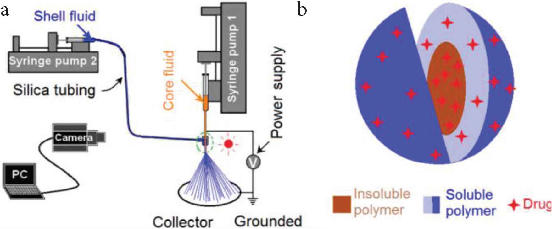
The coaxial electrospraying and its products: (a) a diagram showing the components of an electrospraying system; (b) a diagram showing a combination of insoluble and soluble polymeric matrices in the core–shell structure for drug delivery applications.
Among all types of complex multiple-compartment nanostructures, core–shell structure, reflecting an inner–outer spatial relationship, is the most fundamental and also the most useful one for designing new functional nanomaterials [38–42]. And in the most recent years, the trend that the core–shell structure is explored for drug delivery is increased dramatically. In Web of Science, an investigation about the items of the applications of “core–shell or core-sheath” in “drug delivery” (Search date: 2020-April-15) was carried out. The results and trend are shown in Figure 2. The number for the publications before 1990 is 664, and from 1991 to 1995, a number of 622 is reached during 5 years. In the most recent 5 years, i.e. from 2016 to 2020, the number has soared to 36,748. Most of the core–shell structures are at micro-scale or nano-scale.
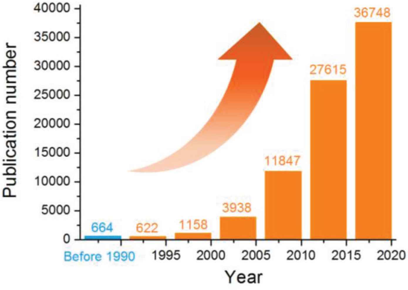
An investigation about the publications in Web of Science about the applications of “core–shell or core-sheath” in “drug delivery” (Search date: 2020-April-15).
The methods reported for creating core–shell nanostructure including the “top-down” methods and “bottom-up” approaches such as molecular self-assembly. Among these methods, coaxial electrospraying (formerly often called as coaxial electrohydrodynamic atomization), as a typical “top-down” physical process, is one of the most popular technique for generating core–shell nanoparticles. All the preparation can be finished within a single step in a straightforward manner. Shown in Figure 3a, the coaxial electrospraying system was arranged in a very compact way. Two alligators were exploited to transfer the high voltages to the working fluids and to remove the electrostatic energy from the deposited particles on the collector, respectively. A digital picture about the co-exist nozzle of the concentric spraying head is shown in the upper-left inset of Figure 3a.
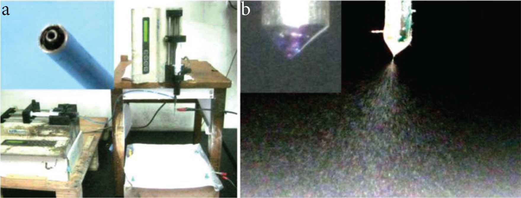
The implementation of coaxial electrospraying processes: (a) the arrangements of electrospraying system for conducting coaxial processes, the upper-left inset shows the nozzle of the spraying head; (b) A digital picture about the coaxial electrospraying of PVP–KET and EC–KET solutions, the upper-right inset shows the compound Taylor cone.
In Figure 3b, a typical electrospraying process was captured using a digital camera under a magnification of 12× and the help of backward illumination. During the optimization processes, the core and shell solutions were added 1 × 10⁻³ mg/mL of basic fuchsin and methylene blue for easy observations, respectively. Indicated by these color markers, the compound Taylor cone, shown in the upper-left corner of Figure 3b, had a clear inner–outer spatial relationship.
3.2. The Morphology and Structure of ENPs
Both KET–PVP and KET–EC solutions were able to be solidified through a single-fluid electrospraying process, which ensured the creation of core–shell ENPs when they were treated together through the concentric spraying head. When the pump driving the core solution was switched off, a single-fluid electrospraying for generating monolithic nanoparticles P1 was conducted. The SEM morphology of these particles are shown in Figure 4a. It is clear that ENPs consisting of PVP and KET had a round morphology with few satellites. Their average diameter was 670 ± 120 nm, as indicated in the bottom inset of Figure 4a. When the pump driving the shell solution was turned off, a single-fluid electrospraying for generating monolithic nanoparticles P2 was similarly conducted. The SEM morphology of these particles are shown in Figure 4b. It is clear that ENPs consisting of EC and KET had a concave morphology with few satellites. Their average diameter was 590 ± 180 nm, as indicated in the bottom inset of Figure 4b. By the way, although both PVP and EC are soluble in ethanol alone, a mixture of ethanol and dichloromethane with a volume ratio of 6:4 was utilized to prepare the working fluids. This is because that dichloromethane has a boiling point of 39.8°C, smaller than 78.3°C of ethanol. The smaller boiling point should be not only beneficial for the solidification of working fluids, but also for keeping the resultant particles a round shape.
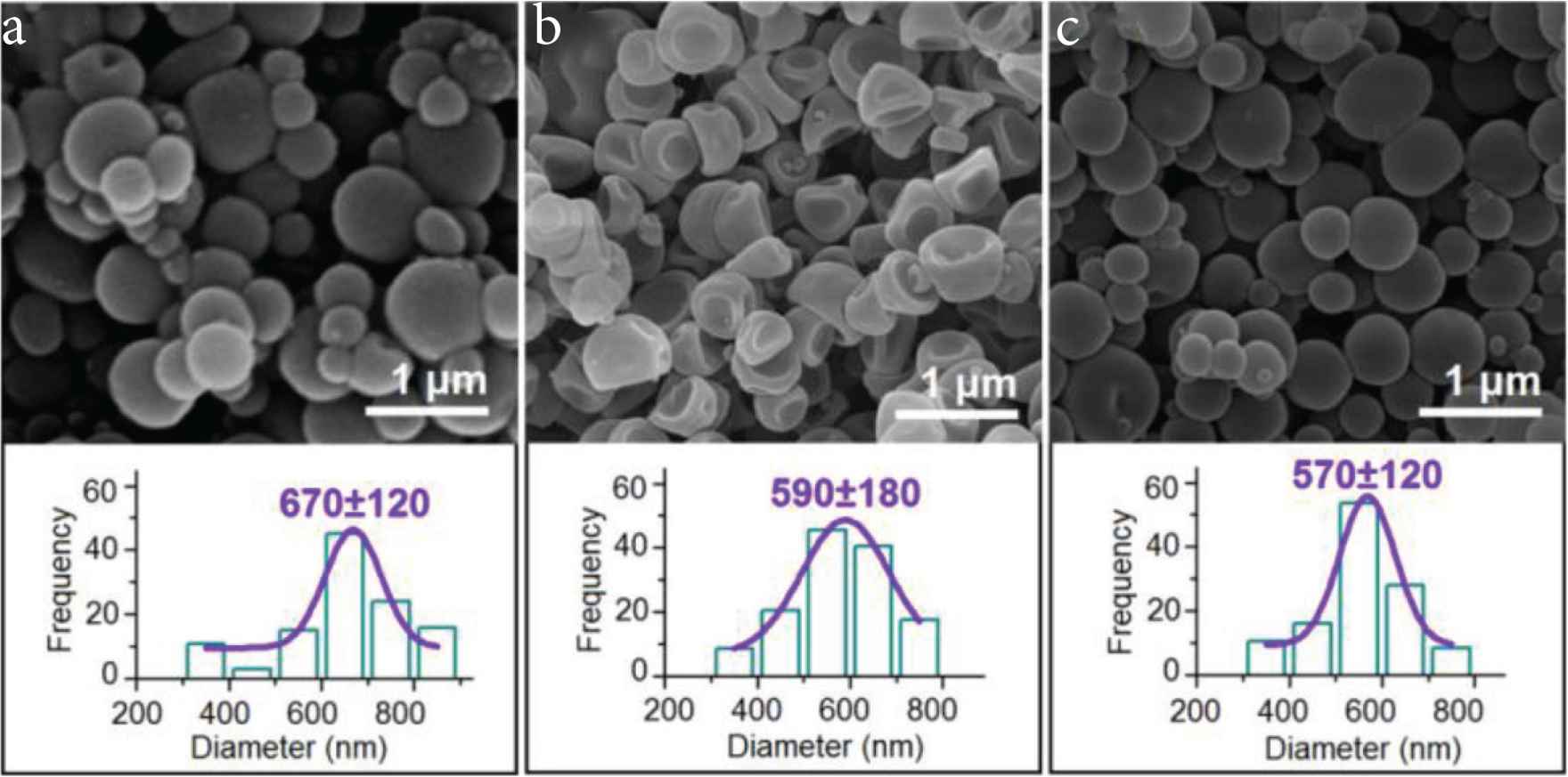
SEM images of the prepared particles and their size distributions: (a) particles P1; (b) particles P2; (c) particles P3.
When both the core and shell fluid pumps were switched on to pump them to the concentric nozzle of spinneret and were guided into the electrical field in a core–shell manner, a coaxial electrospraying process was carried out. Figure 4c provides the morphology and size distribution of the core–shell nanoparticles P3 that were fabricated using a coaxial electrospraying. Similarly, as the monolithic particles comprising the core and shell sections, these core–shell ENPs had a round morphology with few satellites. Their average diameter was 570 ± 120 nm, as indicated in the bottom inset of Figure 4c.
Transmission electron microscope was utilized to determine the inner structures of the three types of ENPs. They images are exhibited in Figure 5. Just as anticipated, monolithic nanoparticles P1 had a homogeneous structure with the drug KET uniformly distributing all over the PVP matrix. The images in Figure 5a indicate that these ENPs had no any multiple-compartment characteristics. The gradually and continuously decreased gray levels from the centre to the boundary are the results of thicknesses variations of the sphere particles P1.
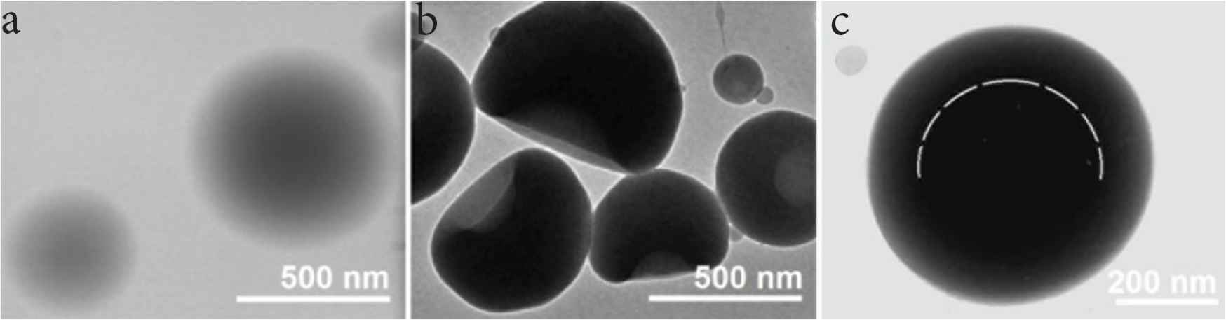
TEM images of the prepared particles and their size distributions: (a) particles P1; (b) particles P2; (c) particles P3.
Figure 5b shows the TEM images of monolithic nanoparticles P2 composed of EC and KET. The concave morphology made these particles have an inhomogeneous gray levels, and the caves were always formed on one side of the EC–KET particles. In contrast, nanoparticles P3 have a round morphology with an obvious inner-outer double-compartment structure. The core section of KET and EC had an obvious deeper gray level than the shell section of KET and PVP. Different with the images of particles P1 with a gradual decrease, particles P3 had a sudden change of gray level, as suggested by the dash lines in Figure 5c. The core section has a diameter of about 400 nm, and the outer doughnut has a thickness of about 70 nm. Thus, the volume ratio can be calculated according to the spherical volume formula, i.e. V = (4/3)πr3. Meanwhile, the mass ratio of the core and shell section can be achieved through their fluid flow rates and the solute concentrations. Thus the ratio of core and shell density can be determined as [(15 + 2)/(4/3)π(2703 − 2003)]:[(10 + 3)/(4/3)π(200)3] = 0.8954, suggesting the shell section had a smaller density than the core section. Thus, the sudden change of gray level is a result of both varied thickness and also the different density.
Microformation mechanism of the core–shell nanoparticles using coaxial electrospraying is suggested in Figure 6. Under an electrical field, the charged fluid will deform from a round droplet to a cone shape, i.e. the well-known Taylor-cone. Because the electrons always distribute on the surface of fluid, thus, the shell fluid should play a dominant role in the formation of Taylor cone. At the tip of Taylor cone, a jet is emitted although it is often very short. Later, an atomization region is presented due to the Coulombic explosion. During the splitting processes of droplets, on one hand, the size of droplets are quickly decreasing. In the other hand, the splitting makes the total fluid’s surface dramatically increase, by which the solvent in the fluid jets will quickly evaporate [43–47]. This process will repeat until the droplets are solidified and then the electrical forces have no enough energy to split the solid particles.
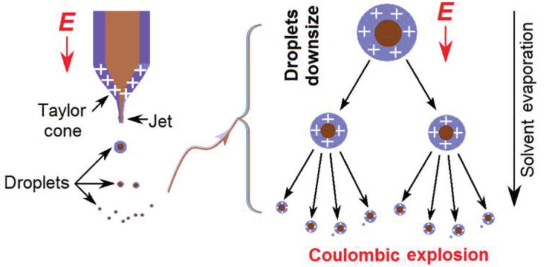
Microformation mechanism of the core–shell nanoparticles using coaxial electrospraying.
3.3. The Physical State and Compatibility
Dissolution and delivery of poorly water soluble drug pose one of the most difficult challenges in pharmaceutics during the past half century. Over 60% of the chemical little molecules have the dissolution issues for an efficacious therapeutic effect. These drugs often present in a crystalline state. When they are incorporated into a compatible polymer, their physical state will change from a crystalline state to an amorphous state, which is favorable for fast dissolution. In pharmaceutics, these drug-polymer materials are called solid dispersion, and in polymer field, they are often termed as medicated polymeric composites [48–50]. PVP is one of the most frequently utilized polymer for forming solid dispersion of poorly water-soluble drug, and is reported to be able to prevent the re-crystallization of over 140 insoluble drugs.
In this study, the raw KET powders are typically crystalline materials, as suggested by the sharp Bragg peaks in its XRD patterns in Figure 7. In sharp contrast, both PVP and EC patterns have no any sharp peaks, indicating that they are amorphous polymers. When these polymers are formed into nanoparticles with KET through the electrospraying processes, the sharp peaks of KET disappeared totally. These phenomena suggested that KET lost its original physical state and was converted into amorphous solid dispersion through the electrospraying, regardless of the single- or double-fluid coaxial processes. These results are similar to the electrospun medicated nanofibers, which have been broadly demonstrated in literature [23,24].
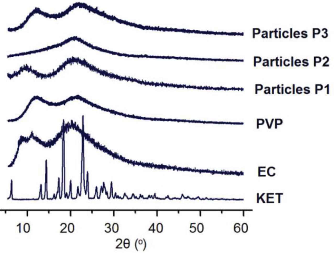
XRD patterns of the electrosprayed particles (P1, P2 and P3) and the raw materials of PVP, EC and KET.
Figure 8 shows the attenuated total reflection fourier transform infrared spectroscopy (ATR-FTIR) spectra of the electrosprayed particles (P1, P2 and P3) and the raw materials of PVP, EC and KET. The wavenumbers at 1655 and 1697/cm suggest that there are two types of crystal dimmers of KET in its crystals, which are formed through different hydrogen bonds. The finger region of KET spectra is full of sharp peaks. However, when KET was incorporated into PVP to form particles P1 and into EC to form particles P2, all the KET’s sharp peaks disappeared from their FTIR spectra. These phenomena suggested that KET has good compatibility with both PVP and EC. There are both –OH and –C=O groups in a ketoprofen molecule, thus, KET can form hydrogen bonds with PVP molecules as a proton donor, and also form hydrogen bonds with EC molecules as a proton acceptor. In the spectra of particles P2, there is a new peak of 1734/cm, which should be a result from a free –C=O group of KET molecule. As for the particles P3, their spectra show a superposition of spectra of particles P1 and P2. There are characteristic peaks of both particles P2 (such as 1064 and 1731/cm) and particles P1 (such as 1288 and 1657/cm), suggesting a hybrid of KET–PVP shell composites and KET–EC core composites.
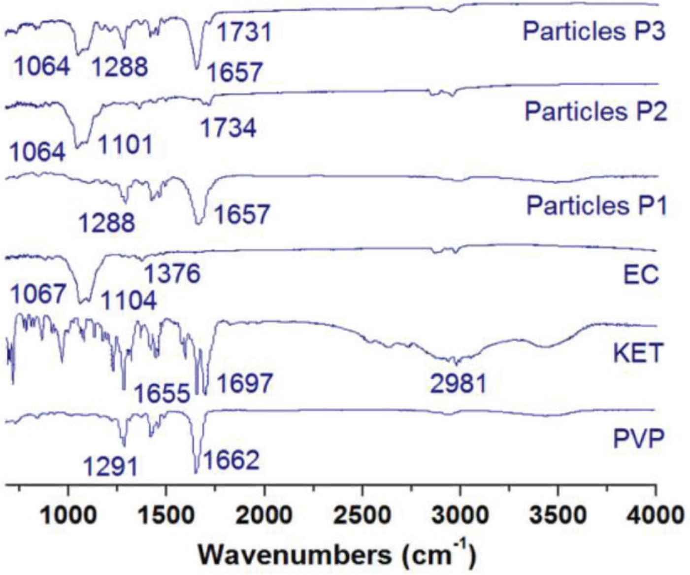
ATR–FTIR spectra of the electrosprayed particles (P1, P2 and P3) and the raw materials of PVP, EC and KET.
3.4. The Drug Encapsulation Ratio Dual-stage Drug Controlled Release Profile
The values of entrapment efficiency (EE%) of KET for particles P1, P2 and P3 are 98.77 ± 6.3%, 101.11 ± 3.8%, and 99.76 ± 5.1%, respectively. These results suggest that all the loaded drug KET was well encapsulated into the particles with the polymeric matrices. Just as the electrospinning process, electrospraying is also an essential physical drying process. The drying rate is extremely fast, often at a range of several decades of milliseconds. Thus, when the working fluids were converted into solid particles, the drug and polymer molecules can keep at a highly homogeneous scattering state, forming molecular composites provided favorite secondary interactions presenting between them. During this quick process, the volatile solvents of ethanol and dichloromethane evaporated to the environment, but the drug and polymer molecules would be “concentrated” together, without any loss to the environment.
Shown in Figure 9a are the in vitro drug release profiles of the three sorts of ENPs. Just as anticipated, particles P1 gave a pulsatile release of KET, 94.1 ± 6.7% of the loaded drug was freed into the dissolution media at the first 5 min and all the drug was released at 10 min (Figure 9b). Both particles P2 and P3 are able to provide a continuous release of KET over 32 h. The release amounts for particles P2 and P3 are 31.4 ± 3.2% and 45.1 ± 4.6%, respectively. However, these two data have totally different meanings that are ignored frequently in literature. For particles P2, an initial release of 31.4 ± 3.2% (>30%) suggested a significant initial burst release effect, which was uncontrollable during a sustained release process. The reasons should be attributed to the abundant distributions of KET molecules on the particles P2’s surface with no diffusion distance and an amorphous state. This kind of phenomenon should be avoided for a fine sustained release.
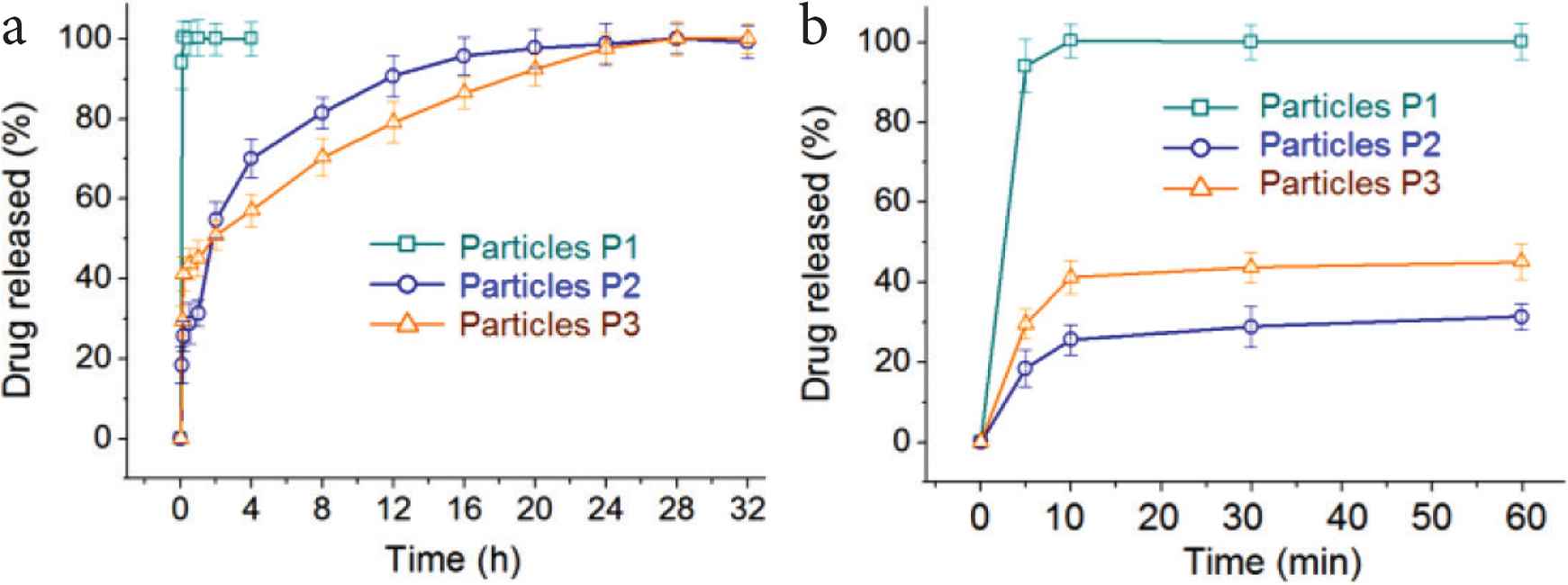
In vitro drug release profiles of (a) the whole time period and (b) the first hour.
As for particles P3, the release of the first hour is 45.1 ± 4.6%. Although this amount value is higher than that of particles P2, this result is reasonable. It is an intentional design of the first stage fast release according to the request of better therapeutic effect. The drug loading amount during the preparation is 2/(2 + 3) × 100% = 40%. The release amount from particles P3 for the 5 and 10 min are 29.6 ± 4.2% and 41.2 ± 3.8%, respectively, suggesting that all the KET loaded with the PVP K10 in the shell section has been dissolved into the dissolution media, similarly with the performances of particles P1. In comparison, the release percentage of particles P2 in the first 10 min is 25.6 ± 3.7% (Figure 9b), reflecting a fast moving of KET from particles P2’s surface to the bulk solutions. The release amount of the 2 h in the acid condition for particles P2 and P3 are 54.7 ± 4.5% and 50.9 ± 3.6%, respectively. This result is unexpected. The reasons should have a close relationship with the concave morphology of particles P2 and the shell PVP sections have effectively retarded the enrichment of KET molecules on the core EC–KET surfaces of particles P3. In a recent review article [21], several strategies are concluded for creating structural nanofibers using multi-fluid electrospinning processes for biphasic drug controlled release profiles. Enlightened by those strategies, some new ways can be imagined for generating novel structural nanoparticles through multi-fluid electrospraying methods. Certainly, the dual-stage release profiles can also be realized through the combinations of different types of water soluble and insoluble polymers [14,38,53].
To further disclose the drug release behaviors from particles P2 and P3, Peppas equation was exploited to regress the drug release data [51]. The results are shown in Figure 10. For nanoparticles P2, the regressed equation is Log Q = 1.5853 + 0.3297 Log torQ = 38.5t0.33 (R = 0.9553), suggesting a typical drug diffusion mechanism controlling the drug molecule dissolution behaviors from the EC matrix (0.33 < 0.45). For the core sections of nanoparticles P3, the regressed equation is Log Q = 1.6336 + 0.2492 Log torQ = 43.0t0.25 (R = 0.9931), suggesting a similar drug diffusion mechanism for the drug molecules to go into the dissolution media from the core EC matrix of particles P3 (0.25 < 0.45).
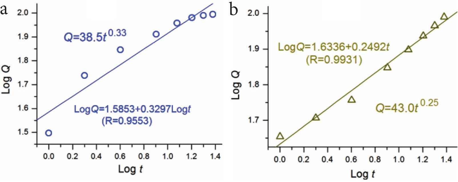
The regressed results of the drug release from the particles P2 (a) and the second release stage of particles P3 (b).
3.5. The Proposed Drug Controlled Release Mechanism
Figure 11 shows a diagram about the mechanism that core–shell structure is explored to furnish a dual-stage drug controlled release profile. In this investigation, the hydrophilic polymer PVP is engineered to be a host shell polymeric matrix to load the drug. PVP is highly hygroscopic. When the core–shell particles encounter water, PVP can be dissolved into water all at one [52–54]. Thus, this property of PVP make sure that the loaded KET molecules can be released instantly with the PVP matrix in an erosion manner. This is the first stage fast release. Certainly, the release amount in the shell PVP section can be facilely adjusted through the addition of KET in the working fluid during preparation.
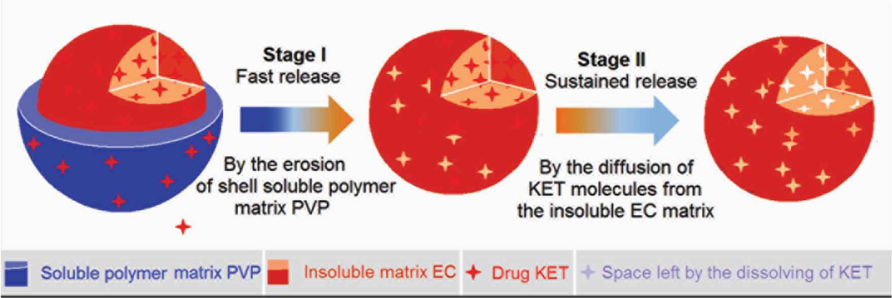
The proposed mechanism of dual-stage release from a core–shell particles consisting of a soluble polymer-based shell for first fast release stage and an insoluble polymer-based core for the second sustained release stage.
When the shell section is removed by the water, the core section appeared in the dissolution media. EC is an insoluble polymer. The prerequisite for the loaded KET molecules to be dissolved into the dissolution media is that the water molecules can penetrate into the EC skeleton for freeing KET molecules from its hydrogen bond with the groups of EC molecules. Later, the free KET molecules penetrate outward to the bulk solutions out of the core sections of core–shell particles. Thus, the second stage of sustained release is inevitably controlled by a diffusion mechanism. Based on the strategy reported here and the combination mechanisms, many other structural dosage forms can be similar developed based on complex structures such as Janus and tri-layer coaxial structures [55–59].
4. CONCLUSION
In this study, with KET as a model drug and PVP and EC as the polymeric carriers, a coaxial electrospraying process was carried out to organize them in a core–shell manner. SEM and TEM results demonstrated that the ENPs from the coaxial process had a round morphology and an obvious core–shell structure, with an average diameter of 570 ± 120 nm and an estimate thickness of 70 nm. KET presented in the ENPs in an amorphous state owing to the fine compatibility between KET and its carriers, as verified by XRD and FTIR measurements. The drug can be encapsulated into the polymeric matrices completely. In vitro dissolution tests exhibited that the core–shell ENPs were able to provide a designed dual-stage controlled release profile with an amount of 45.1 ± 4.5% for the first stage. Core–shell nanostructure has its flexibility and applicability of tailoring components and spatial distributions for achieving the designing functional performances, and coaxial electrospraying is able to provide a strong support for the facile fabrication of core-shell nanoparticles.
CONFLICTS OF INTEREST
The authors declare they have no conflicts of interest.
AUTHORS’ CONTRIBUTION
DY and PW contributed in conceptualization. PW, MW, XW, Honglei Z and Heng Z contributed in experiments. PW and MW contributed in writing-original draft preparation. All authors contributed in writing-review and editing. DY contributed in supervision and project administration.
ACKNOWLEDGMENTS
The financial support from
Footnotes
REFERENCES
Cite this article
TY  - JOUR
AU  - Pu Wang
AU  - Meng-long Wang
AU  - Xi Wan
AU  - Honglei Zhou
AU  - Heng Zhang
AU  - Deng-Guang Yu
PY  - 2020
DA  - 2020/08/31
TI  - Dual-stage Release of Ketoprofen from 	Electrosprayed Core–Shell Hybrid Polyvinyl Pyrrolidone/Ethyl Cellulose Nanoparticles
JO  - Materials Highlights
SP  - 14
EP  - 21
VL  - 1
IS  - 1-2
SN  - 2666-4933
UR  - https://doi.org/10.2991/mathi.k.200825.001
DO  - 10.2991/mathi.k.200825.001
ID  - Wang2020
ER  -