
A Computational Study of the Effect of Stent Design on Local Hemodynamic Factors at the Carotid Artery Bifurcation
 , Xiao Yun Xu1, *,
 - DOI
- 10.2991/artres.k.200603.001How to use a DOI?
- Keywords
- Carotid artery stenting; hemodynamics; in-stent restenosis; computational fluid dynamics
- Abstract
Background: Previous clinical studies have shown that the incidence of restenosis after carotid and coronary stenting varies with stent design and deployment configuration. This study aims to determine how stent design may affect in-stent hemodynamics in stented carotid arteries by means of Computational Fluid Dynamics (CFD).
Methods: A robust computational method was developed to integrate detailed stent strut geometry in a patient-specific carotid artery reconstructed from medical images. Three stent designs, including two closed-cell stents and one open-cell stent, were reproduced and incorporated into the reconstructed post-stent carotid bifurcation. CFD simulations were performed under patient-specific flow conditions. Local hemodynamic parameters were evaluated and compared in terms of Wall Shear Stress (WSS), Oscillatory Shear Index (OSI) and Relative Residence Time (RRT).
Results: All simulated stent designs induced some degree of flow disruption as manifested through flow separation and recirculation zones downstream of stent struts and quantified by WSS-related indices. Compared to the simulated open-cell stent, closed-cell stents created slightly larger areas of low WSS, elevated OSI and high RRT, due to a greater number of stent struts protruding into the lumen.
Conclusion: Detailed stent design and patient-specific geometric features of the stented vessel have a strong influence on the evaluated hemodynamic parameters. Our limited computational results suggest that closed-cell stents may pose a higher risk for in-stent restenosis (ISR) than open-cell stent design. Further large-scale prospective studies are warranted to elucidate the role of stent design in the development of ISR after CAS.
- HIGHLIGHTS
- •
This study provides a detailed analysis of in-stent hemodynamics in post-stenting carotid arteries under patient-specific anatomical and flow conditions.
- •
Three different carotid stents are modelled and virtually implanted into a carotid artery bifurcation reconstructed from computed tomography images.
- •
Results from this study offer more insights into the differences in hemodynamic measures between open- and closed-cell stents, which are essential for evaluating the risk of in-stent restenosis.
- •
The computational method used in this study offers a useful tool for future improvement and optimisation of carotid stent designs.
- •
- Copyright
- © 2020 Association for Research into Arterial Structure and Physiology. Publishing services by Atlantis Press International B.V.
- Open Access
- This is an open access article distributed under the CC BY-NC 4.0 license (http://creativecommons.org/licenses/by-nc/4.0/).
1. INTRODUCTION
Carotid Artery Stenting (CAS) is a recognised alternative procedure to Carotid Endarterectomy (CEA) for the treatment of severe carotid stenosis, especially when patients age and anatomy, surgical risk and clinical experience are considered in the choice of treatment [1–4]. Specifically, CAS is considered for patients at high-risk for surgery owing to anatomical and/or clinical factors, such as contralateral laryngeal-nerve palsy, previous radical neck surgery, or restenosis after CEA [5,6], but it is not recommended for acutely symptomatic patients [6,7]. Its minimally invasive nature, together with the increased number of trained physicians, has made CAS widely adopted in routine clinical practice [2,8–11]. Despite this fact, the need for CAS has been debated in several clinical controversies and it has been the subject of intense investigation since its first application [12].
In-stent Restenosis (ISR) has been reported as a long-term complication which can arise from CAS. Previous clinical trials have reported variable ISR rates depending on the criteria used [13–15]. The secondary analysis of Carotid Revascularization Endarterectomy versus Stenting Trial [13] reported a 6.0% ISR incidence in 2 years based on narrowing of ≥70% and Peak Systolic Velocity (PSV) ≥300/cm. A 10-year follow-up study reported a cumulative ISR incidence of 12.2% [2]. Using a slightly different criterion with a lower PSV, International Carotid Stenting Study (ICSS) [16] reported ISR incidences of 6.9% and 10.8% at 1- and 5-year follow-up, respectively. Another major trial that defined ISR as narrowing of ≥50% (with PSV ≥175/cm) reported ISR incidences of 3.9% and 6.0% at 3- and 5-year follow-up, respectively [17]. Restenosis after CAS is mainly attributed to neointimal hyperplasia and vascular remodelling or recurrent atherosclerosis [13,18] as a healing response to tissue injury induced by stent implantation. It has been suggested that the incidence of restenosis may be influenced by stent design and stenting configuration [18–24], and the location of ISR correlated consistently with regions of low Wall Shear Stress (WSS) [25–27].
Differences in stent design contribute to disparity in WSS distribution as the presence of stent struts in the arterial wall creates local flow disturbances between the strut edges protruding into the lumen. Several studies used WSS as a hemodynamic risk indicator to identify potential regions of restenosis after CAS [25,26,28] and to determine the optimal stent type for specific vessels [25,29]. Uemiya et al. [26] compared hemodynamic changes in pre-, post- and follow-up CAS models of five patients. Their computational results showed low flow rate and significant variations of WSS in the Internal Carotid Artery (ICA) of patients who developed restenosis at follow-up. Although the stent strut geometry was not reconstructed in their post-stent models - which limited the ability for detailed quantitative analysis of near wall parameters - their preliminary results were useful in predicting hemodynamic variations before and after CAS.
Building patient-specific post-stent models is challenging due to imaging artefacts caused by the metallic struts in medical images acquired using Computed Tomography Angiography (CTA) or Magnetic Resonance Imaging (MRI) [29,30], which are commonly adopted for the reconstruction of patient-specific vascular models. Creating a good quality mesh that is able to capture the protrusion of thin stent struts into the blood volume is also a difficult task. In this study, a rapid and robust computational method was developed for patient-specific simulations of CAS. This consists of reconstruction of the actual stent geometry, the details of its strut design and its incorporation into the fluid domain. It has been applied to three different stent designs representing an open- and two closed-cell stents implanted in a highly stenosed carotid artery bifurcation reconstructed from CTA images. Comparisons were made between the pre- and post-stent models, and between the models with different stent designs: the original model with a closed-cell stent design, and two additional stent designs (one closed- and open-cell). The contralateral carotid artery bifurcation in the same patient was also included as a control.
2. MATERIALS AND METHODS
2.1. Patient Information
A 68-year-old male patient with asymptomatic chronic stenosis (90% according to NASCET grading) in his right ICA was examined using contrast-enhanced CTA. Pre-stenting assessment of the neck confirmed the presence of a significant fibrocalcific plaque in the right ICA. The patient was recommended for carotid artery stenting. An 8F guiding catheter was inserted into the carotid artery from the femoral artery. A balloon pre-dilation of the tight stenosis was performed using a 3 mm-diameter balloon, which was then removed and a self-expanding Wallstent (Carotid WALLSTENT™ 6–8 × 37 mm, Boston Scientific, MA, USA) was deployed in the ICA and distal to the Common Carotid Artery (CCA), followed by post-stenting dilation using a 4 mm-diameter balloon to ensure good stent positioning. Pre- and post-stent CTA images were acquired and used to reconstruct patient-specific models for computational simulations. In addition, Doppler ultrasound velocity measurements were available for the normal left carotid arteries and the right carotid arteries after stenting. According to the guidelines and regulations of the NHS Health Research Authority, formal ethical approval was not required for this limited, retrospective and anonymised study.
Three carotid bifurcation models were reconstructed from CTA scans of the same patient (Figure 1): a healthy carotid for the normal left carotid bifurcation, a stenosed carotid for the right carotid artery bifurcation before stenting and its post-stent model. Details of the CTA acquisition and carotid lumen segmentation can be found in Appendix A.
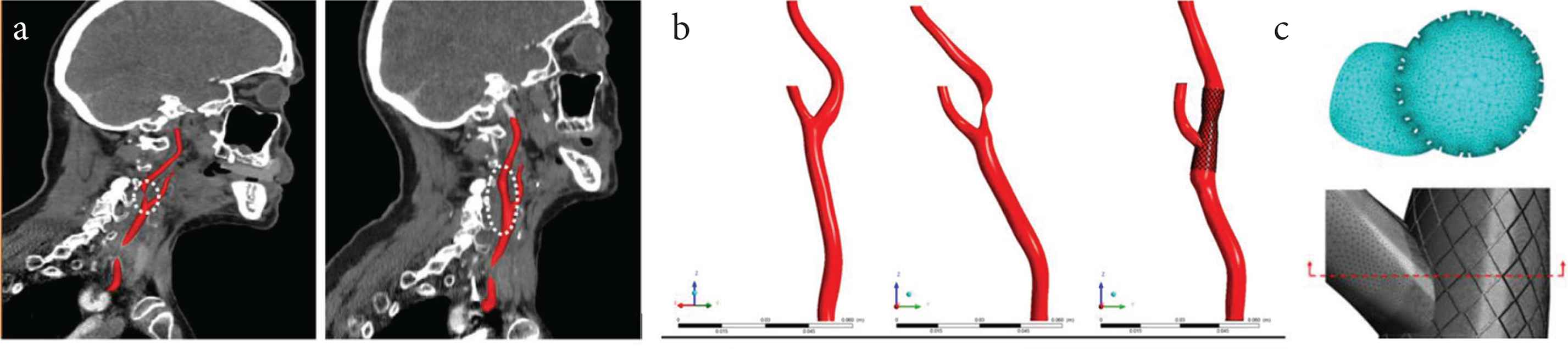
Details of the carotid artery bifurcation models. (a) Oblique sagittal view of the stenosed right carotid artery bifurcation (left) and the stented carotid bifurcation obtained a week after the procedure (right). (b) 3D reconstruction of the three different models under investigation: the healthy left carotid bifurcation (left), the stenosed right carotid bifurcation (middle), and the post-stent right carotid bifurcation (right). (c) particular of the tetrahedral mesh at the vicinity of the stent struts.
2.2. Stent Creation and Virtual Implantation
To account for the actual stent geometry, as well as details of its strut design and its presence at the External Carotid Artery (ECA) ostium, a rapid and robust procedure was developed to virtually implant a chosen stent into a patient-specific model (Figure 2). This procedure makes use of the following information: (1) geometry of the post-stent carotid bifurcation; and (2) stent-specific properties including the number and width of cells, circumferential or longitudinal struts, as well as the overall stent length and diameter. To virtually implant the stent, a series of Boolean operations were performed. First, the stented segment was extracted from the post-stent model for virtual stenting (Figure 2a–c). This segment was then wrapped with the parameterized sketch of stent cells and hollowed by 0.24 mm according to the stent strut thickness (Figure 2d and e). An intersection Boolean operation was performed between the stent cell geometry and the stented segment in order to remove the vessel and isolate the stent geometry (Figure 2f). Finally, the stent geometry was embedded into the patient-specific post-stent model (Figure 2g). Explicit representation of the stent struts at the ECA ostium is important for evaluating the effect of stent design and location on post-stent carotid hemodynamics.
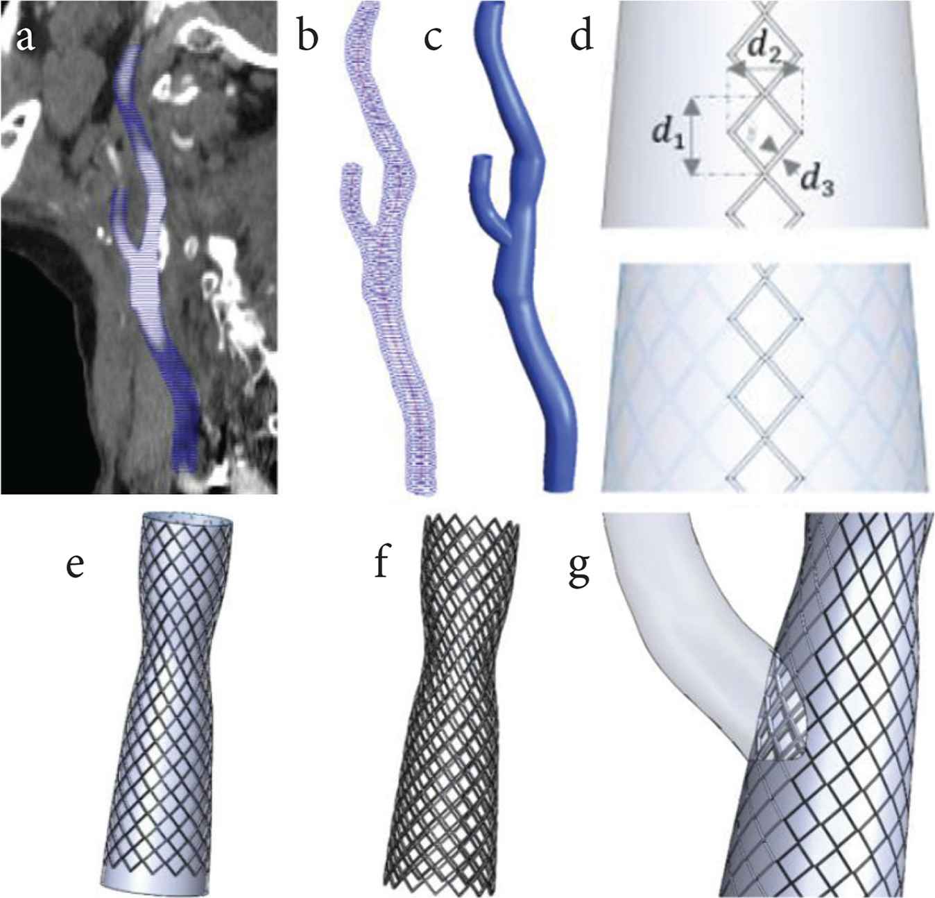
Workflow: (a) Segmented CT images are used to generate polylines of the stented carotid bifurcation; (b) Polylines and centrelines are exported to CAD software for (c) lofting to create a 3D solid model; (d) Parameterized sketch of the stent cell is (e) wrapped around the solid wall representing the stented region (CCA and ICA); (f) Intersection of the stent strut and the solid wall yields the expanded stent, and (g) subtraction from the solid post-stent model to produce a stented carotid bifurcation for CFD simulation.
To investigate the influence of open and closed-cell stent designs on blood flow patterns, models for the deployed Wallstent (Stent A) and two additional commercial stent designs were built (Figure 3). Stent B was created to represent another closed-cell stent design resembling a XACT stent (XACT® Carotid stent system, Abbot Vascular, CA, USA) and Stent C was created for an open-cell design to resemble an ACCULINK stent (RX ACCULINK™, Abbot Vascular, CA, USA). Details of the geometric parameters are summarised in Appendix B. The models were discretised into tetrahedral elements using ANSYS ICEM CFD 15.0 (Canonsburg, PA, USA). Figure 1c shows the mesh elements generated with local refinement around the stent struts where the mesh density was much higher than in other regions. The post-stent models consist of approximately 7 million elements, while the stenotic and healthy models consist of approximately 3 million elements each.
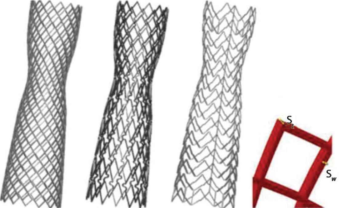
Details of the three different stent geometries in deployed configuration. Starting from the left are WALLSTENT (Stent A), Stent B and C; the latter represent XACT and ACCULINK, respectively. A single free cell area at the far right defines the strut thickness (St) and strut width (Sw).
2.3. Flow Simulations
Laminar and pulsatile blood flows were simulated by numerically solving the governing equations for an incompressible fluid using a finite volume-based CFD code (ANSYS CFX 15.0). For the pre-stent stenosed carotid where the maximum local Reynolds number at the throat was around 1430, the shear stress transport turbulence model incorporating the γ-Reθ transitional model was used to better capture disturbed blood flow features [31,32]. Blood was treated as incompressible and non-Newtonian with a density of 1060 kg/m3 while its viscosity was described using the Quemada model for a haematocrit of 0.45 [33,34].
Fully-developed flow was assumed at the inlet where Womersley velocity profiles were specified which corresponded to the patient-specific CCA flow waveforms acquired with Doppler ultrasound. The 3-element Windkessel model was applied at both the ICA and ECA outlets, and all model parameters were calibrated using the measured flow waveforms at the outlets as well as the maximum, minimum and cycle-averaged pressures of 110, 70 and 90 mmHg, respectively. For the pre-stent model, since flow information was not available, an empirical ICA:ECA flow split was assumed according to the degree of stenosis [35]. The walls were assumed to be rigid with no-slip conditions. A schematic illustration of the computational model and the applied inflow waveforms can be found in Appendix C. The aforementioned boundary conditions were implemented in ANSYS CFX through FORTRAN subroutines. A uniform time-step of 0.001 s was adopted, and a periodic solution was achieved after three cardiac cycles.
3. RESULTS
3.1. Flow Patterns
From the flow rate waveforms shown in Figure 4a the ICA:ECA flow splits can be determined - these are 52:48, 20:80 and 62:38 for the healthy, stenotic (pre-stent) and post-stent models, respectively. Note that flow waveforms for the normal left carotid bifurcation and the post-stent right carotid bifurcation were obtained from Doppler ultrasound measurements. For the pre-stent right carotid bifurcation, ultrasound measurements were not available, hence the flow waveform in the CCA was assumed to be the same as the pre-stent waveform, with the ICA:ECA flow split being determined based on the degree of stenosis as explained earlier. The abnormal flow split in the pre-stent carotid reflects the consequence of the severe stenosis (90%) in the ICA, forcing most of the flow through the ECA, whereas the improved flow split in the post-stent model demonstrates the effectiveness of CAS in restoring ICA flow.
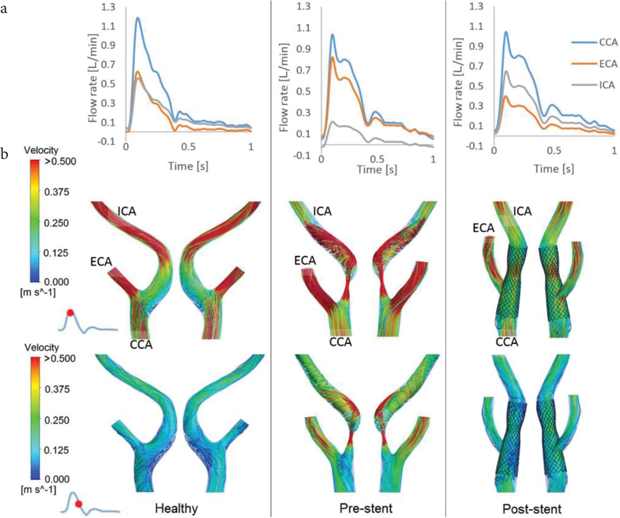
Flow patterns in the healthy, pre- and post-stent models. (a) Flow rate waveforms in the CCA, ICA and ECA. (b) Comparison of instantaneous velocity streamlines in the bifurcation region of the three models at two time points over the cardiac cycle.
It is clear from the instantaneous velocity streamlines in Figure 4b that there are distinctly different flow features in the three models. The healthy carotid bifurcation is characterised by low velocities in the bulb due to localised expansion of lumen area where flow separation and recirculation occur during part of the cycle. The presence of a 90% stenosis in the pre-stent model dramatically altered the flow pattern which is featured by a high-velocity jet from the throat, flow separation immediately after the stenosis and a strong helical flow structure downstream of the stenosis. Blood flow is significantly improved after stenting. However, the carotid artery was straightened by the implantation of a relatively stiff stent, which also created discontinuity in surface curvature at the proximal and distal ends of the stent. Furthermore, the stent was purposely deployed with a mild ‘waist-shape’ to avoid extensive plaque rupture and embolisation through the stent mesh during stenting. This created a local constriction with up to 15% reduction in luminal diameter (Figures 1 and 4b). These geometric features caused local flow disruptions in the proximal region of the constriction especially along the outer wall opposite to the ECA ostium, and at the distal end of the stent. Secondary flow and small recirculation are also observed near the entrance to the stented segment in the CCA where the stent bends about 20° from the host artery.
Flow patterns in Stent A (the stent deployed in the patient) are compared with two other models which were artificially created to mimic another closed-cell stent (Stent B) and an open-cell stent (Stent C), respectively. All post-stent models have similar flow patterns, with only minor differences in the proximal and distal regions of the stented segment (Appendix D). To further examine the influence of different stent designs, velocity contours and streamlines in the stented region are displayed in the coronal and transverse planes (Figure 5). At peak systole, several small vortices in flow recirculation zones can be identified in the coronal planes of all models as highlighted by yellow stars: one near the proximal end of the stent, one just after the ECA ostium at the lower wall, and another two downstream of the ‘waist’ of the stent (Figure 5a). At maximum flow deceleration, the recirculation zones are still present at the same locations but become much larger. There is a new recirculation zone along the outer wall opposite the ECA entrance as a result of the combined effect of branching and flow deceleration. On the transverse plane cutting across the ECA and ICA at the bifurcation (Figure 5b), isolated high velocity spots are seen between the stent struts at the ECA ostium as flow passes through the open cells at peak systole. There are more high velocity spots in Stent A, but they are smaller in size compared to Stents B and C. In the ICA cross-section, the core region with velocities >0.375 m/s is much larger with Stent A due to higher flow resistance posed by the stent struts at the ECA ostium. Velocity contours at systolic deceleration are similar in all models, showing a pair of counter-rotating vortices in ICA and small flow recirculation zones in-between stent struts (as highlighted by the inset figure in Figure 5).
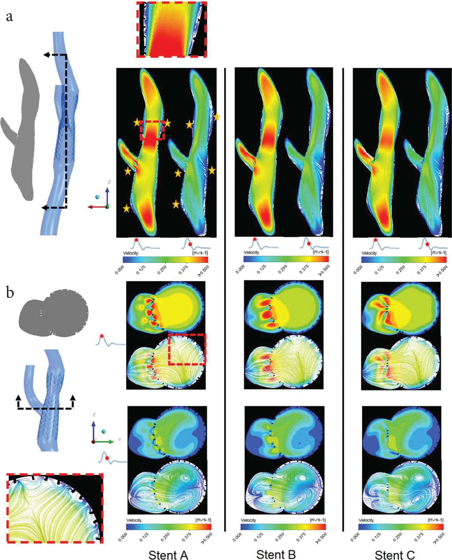
Instantaneous velocity streamlines plotted on the two cut planes dividing the stented regions: (a) The coronal plane and (b) the transverse plane. The inset figures show examples of flow recirculation and the yellow stars indicate locations of flow recirculation.
3.2. Wall Shear Stress-related Indices
Time-averaged WSS (TAWSS), Oscillatory Shear Index (OSI) and Relative Residence Time (RRT) were calculated to identify regions of unfavourable hemodynamic conditions that may induce neointimal hyperplasia, leading to subsequent restenosis. As shown in Figure 6a, TAWSS in the healthy carotid is characterised by low values in the carotid bulb due to localised flow recirculation, and a small band of relatively high values in the ECA. The stenosed carotid (pre-stent model) exhibits considerable spatial variations in TAWSS, as a result of the tight stenosis in the ICA. Extremely high TAWSS values are observed at the centre of the stenosis where the maximum value is up to 73 N/m2 (Pa), and in the downstream region along the outer wall impinged by the high-velocity jet.
In the post-stent models, TAWSS is much lower than in the pre-stent and healthy models, with only isolated spots of elevated TAWSS around the flow divider and stent struts at the ECA ostium (Figure 6b). Since low TAWSS (<0.4 Pa) is considered to be atheroprone [36], areas with TAWSS <0.4 Pa were measured as percentage of the total geometry area and compared. Table 1 shows that both closed-cell stent models (Stent A and B) have larger areas of TAWSS <0.4 Pa than Stent C. In addition to TAWSS, OSI and RRT were also evaluated and compared. It is clear that both Stent A and Stent B have larger areas of high OSI (>0.1) and RRT (>10/Pa) than Stent C. Figure 6c and 6d shows the contours of OSI and RRT in all stent models where regions of high OSI and RRT are often co-located. High OSI and RRT are observed in the proximal and distal regions of the ‘waist’, mostly at the stent strut interconnections.
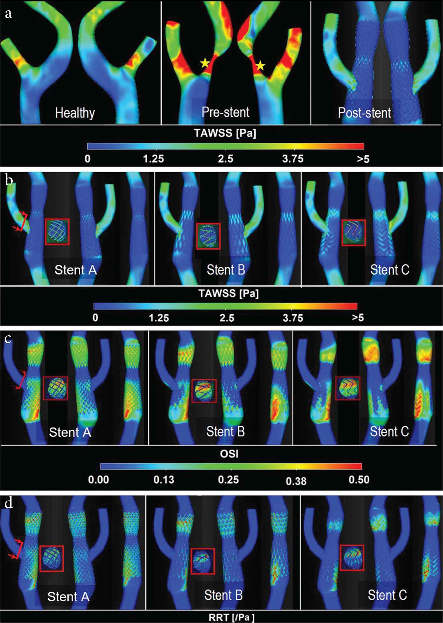
Contours of TAWSS, OSI and RRT. (a) TAWSS distribution for healthy, pre-stent and post-stent models, where yellow stars indicate the location of maximum TAWSS due to high-velocity jet through the throat. Three views of different post-stent models comparing TAWSS (b), OSI (c) and RRT (d) distributions are shown for clarity. Distributions of WSS indices on the stent strut at the ECA ostium are also shown (inset).
| TAWSS [Perc. area of TAWSS <0.4 Pa] (%) | OSI [Perc. area of OSI >0.1] (%) | RRT [Perc. area of RRT >10] (%) | |
|---|---|---|---|
| Stent A | 28.29 | 26.72 | 16.92 |
| Stent B | 24.13 | 24.13 | 12.60 |
| Stent C | 22.75 | 23.51 | 10.58 |
| Normal | 3.93 | 8.69 | 0.89 |
| Stenotic | 2.93 | 5.94 | 1.04 |
Percentage areas of low TAWSS, elevated OSI and high RRT for all post-stent models. Results for the normal left carotid artery bifurcation and stenosed right carotid bifurcation before stenting are included for comparison
4. DISCUSSION
In-stent restenosis is a long-term complication which can arise after CAS. Welt and Rogers [37] presented an integrated view of the pathophysiological processes underlying ISR, showing continued vascular smooth muscle cell proliferation and monocyte recruitment as the main causes for neointimal thickening in the weeks after endothelial injury. On the other hand, hemodynamic factors, such as WSS, are involved in regulating the behaviour of smooth muscle cells, with low WSS being associated with up-regulation of proinflammatory genes and enhanced smooth muscle cell proliferation and migration [38,39].
Several studies have compared the short- and mid-term results of open- and closed-cell stent designs [18,19,21,23,40,41], but no consensus has been reached as to which type of stent would be less likely to cause ISR in the long-term. Therefore, more studies are needed to elucidate the role of stent design in the development of ISR. In this study, we investigated the effect of stent design on local hemodynamic factors by adopting a robust computational procedure to construct stent cell geometry and to embed this in a patient-specific carotid bifurcation reconstructed from CTA images acquired after CAS. This allowed us to compare changes induced by open- and closed-cell stent designs in flow patterns and shear stress-related indices. Our method differs from previous finite element method-based studies [25,28,42] by using a parametric design technique to model the deployed stent configuration. The use of Boolean operations to reconstruct the post-stent patient-specific model is not only computationally efficient, but can also retain faithfully the original geometric features. This advantage can be appreciated through the replication of a mild constriction in the middle of the stent (Figure 1), which was created to avoid embolisation due to overdilation with a high pressure that may compress the atherosclerotic plaque [43], and other features such as the immersed stent struts at the ECA entrance and the bends at the proximal and distal ends of the stent.
Analysis of flow and hemodynamic indices in the pre-stent model showed the dramatic impact of the high grade (90%) stenosis, with increased velocities at the tight throat resulting in extremely high local WSS which far exceeded the normal physiological threshold of 7 Pa [36]. High shear stress is likely to lead to matrix degradation and weakening of the plaque cap in the endothelium, which may cause rupture [36,44]. CAS effectively restored blood supply to the ICA, achieving a normal ICA:ECA flow ratio of 62:38 after stenting. However, detailed analysis of flow patterns and WSS-related indices revealed much larger areas of low WSS (TAWSS <0.4 Pa), elevated OSI (>0.1) and high RRT (>10/Pa) in all post-stent models compared to the normal control (Table 1). As low TAWSS, large OSI and high RRT are correlated with neointimal thickening which could potentially lead to ISR [25,27], our computational results appeared to suggest that the closed-cell post-stent models (Stent A and B) fared slightly worse than the open-cell model (Stent C) in that the modelled closed-cell stents had larger surface areas exposed to unfavourable hemodynamic conditions. This can be explained by taking a close look at the locations of low TAWSS, elevated OSI and high RRT in the post-stent models. Regardless of the stent cell geometry, these can be found in both the proximal and distal portions of the stent, as a result of sudden changes in surface curvature and the presence of a mild ‘waist’ shape in the middle of the stent. While these geometric features were present in all post-stent models, differences in stent cell design were reflected in the number of struts and cell size, with closed-cell stents having more struts protruding into the lumen causing more localised flow disturbances in-between the struts. Our results are consistent with a recent study by Texakalidis et al. [19] who found that open-cell stents were associated with a statistically lower risk of restenosis compared to closed-cell stents.
The computational model used in this study has a number of limitations. First, the stent deployment method did not consider mechanical interactions between the stent struts and the vessel wall, bypassing the finite element analysis-based procedure for virtual stent implantation. Nevertheless, the reconstruction procedure adopted in this study incorporated the best-fitted stent scaffolding based on the technical specification of the stent and also the patient-specific geometry [45]. A similar strategy was used for all simulated stents to ensure consistency in the results. Second, a rigid wall assumption was made in all CFD simulations. Since the focus of this study was on hemodynamic parameters, the rigid wall assumption is expected to have a minor influence on the results in the stented region [46]. Nevertheless, it has been shown that fluid–structure interaction simulations might be necessary for assessing OSI and RRT [47]. Third, in this study, new hybrid stent designs were not included. The absence of follow-up data also limited the scope of the study in searching for any direct correlations between the predicted hemodynamic parameters and ISR.
5. CONCLUSION
In this study, we used a computationally efficient method for stent deployment in patient-specific carotid arteries reconstructed from CTA images. In order to investigate the impact of stent design on in-stent hemodynamics and the potential development of ISR, we compared flow patterns and WSS-related indices between three different stent designs and with a normal control. Our results clearly show that while the CAS procedure effectively restored a normal flow distribution through the severely stenosed right carotid bifurcation, all post-stent models exhibited atheroprone and procoagulant flow conditions as measured by the WSS-related indices. Comparisons of the closed- and open-cell stents suggested that closed-cell stents created slightly larger areas of low TAWSS, elevated OSI and high RRT, which may be indicative of an increased risk for ISR. In addition to detailed stent design, patient-specific geometric features, such as changes in vessel curvature at the proximal and distal ends of the stent and changes in lumen diameter, were found to have a strong influence on the evaluated hemodynamic parameters. Therefore, these features should be reserved in patient-specific computational models for assessing the risk of ISR after CAS.
CONFLICTS OF INTEREST
The authors declare they have no conflicts of interest.
AUTHORS’ CONTRIBUTION
MH and XYX were responsible for the study conceptualization and supervised the project. Data curation, formal analysis were carried out by NHJ and was also responsible in writing (original draft) the manuscript. Funding acquisition and project administration was done by NHJ and XYX Review and editing of the final manuscript were done by MH and XYX.
FUNDING
NHJ was supported by a PhD scholarship awarded by the
APPENDIX A. Reconstruction of the carotid artery bifurcation
The pre-stent images (acquired with SIEMENS SOMATOM Definition AS) contained 200 slices with a slice thickness of 1 mm, interslice distance of 1 mm and pixel size of 0.467 mm. For post-stent imaging, a different scanner was used (Philips Ingenuity CT) with a slightly lower resolution: 100 slices of the carotid artery were taken with a thickness of 2 mm for each slice, interslice of 1 mm and pixel size of 0.549 mm.
A segmentation technique based on thresholding and region growing was used to delineate the inner surface of the carotid artery using MIMICS 16.0 (Materialise Inc., Leuven, Belgium). Smoothing was performed for lumen contours and surfaces, in order to correct registration errors and avoid results with spurious WSS values. Polylines of the segmented post-stent geometry were also created together with the centreline path before being exported to SolidWorks 2012 (Dassault Systems, Velizy, France) for lofting. Since the stenosis affected only the right ICA, the contralateral left carotid bifurcation was used as a normal healthy model for comparison.
APPENDIX B
| Model | Stent A | Stent B | Stent C |
|---|---|---|---|
| Configuration | Straight | Straight | Straight |
| Cell type | Closed-cell | Closed-cell | Open-cell |
| Strut thickness (St) [mm] | 0.24 | 0.24 | 0.24 |
| Strut width (Sw) [mm] | 0.1 | 0.1 | 0.1 |
| Stent diameter (max) [mm] | 8 | 8 | 8 |
Design parameters for three carotid stents (data were adopted from Auricchio et al. [42])
APPENDIX C
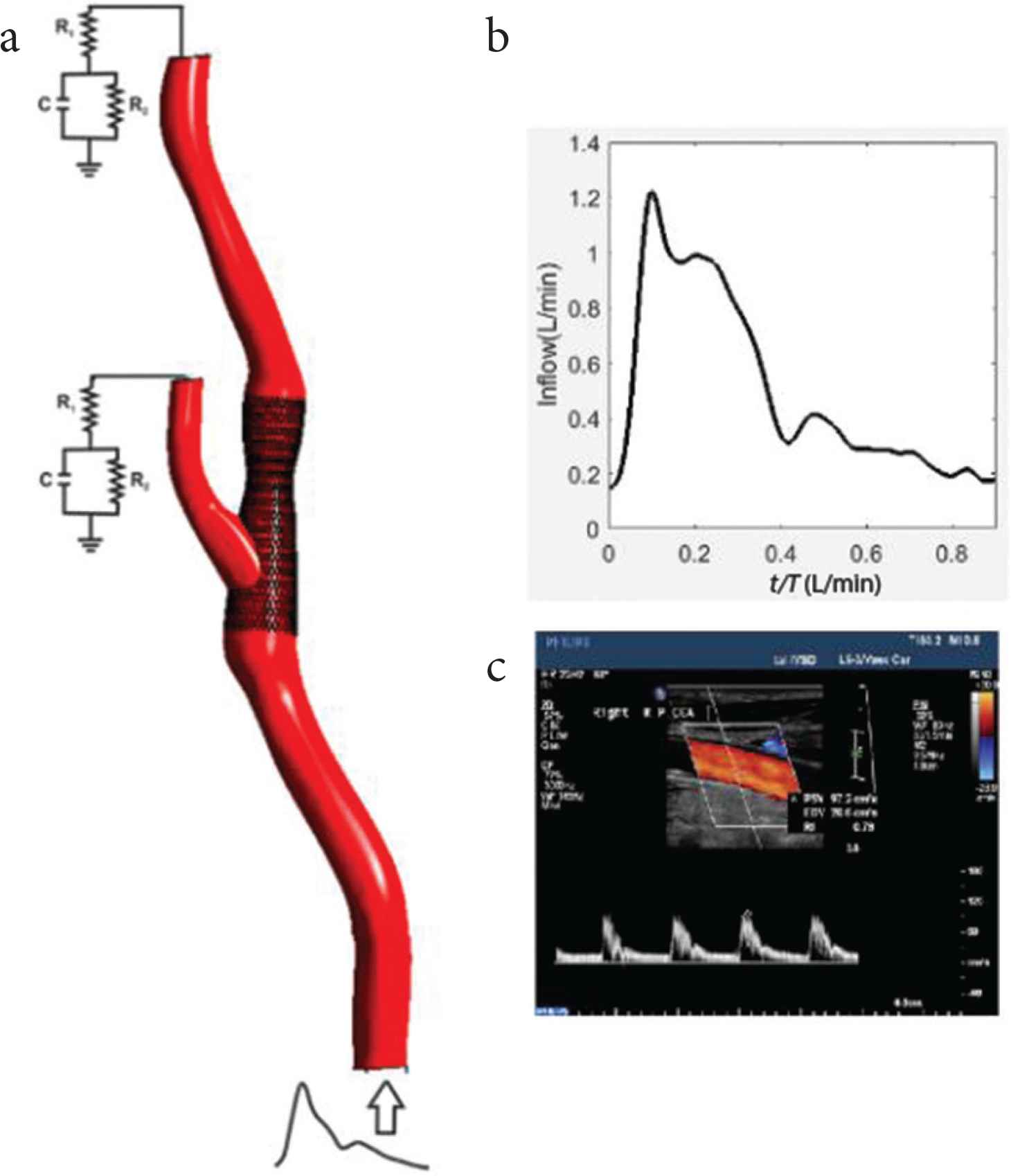
Schematic of the computational model utilized in this study. (a) The carotid bifurcation model together with the RCR network model at the ECA and ICA outlets and (b) the inflow waveform prescribed at the CCA inlet section based on (c) Doppler ultrasound velocity measurements.
APPENDIX D
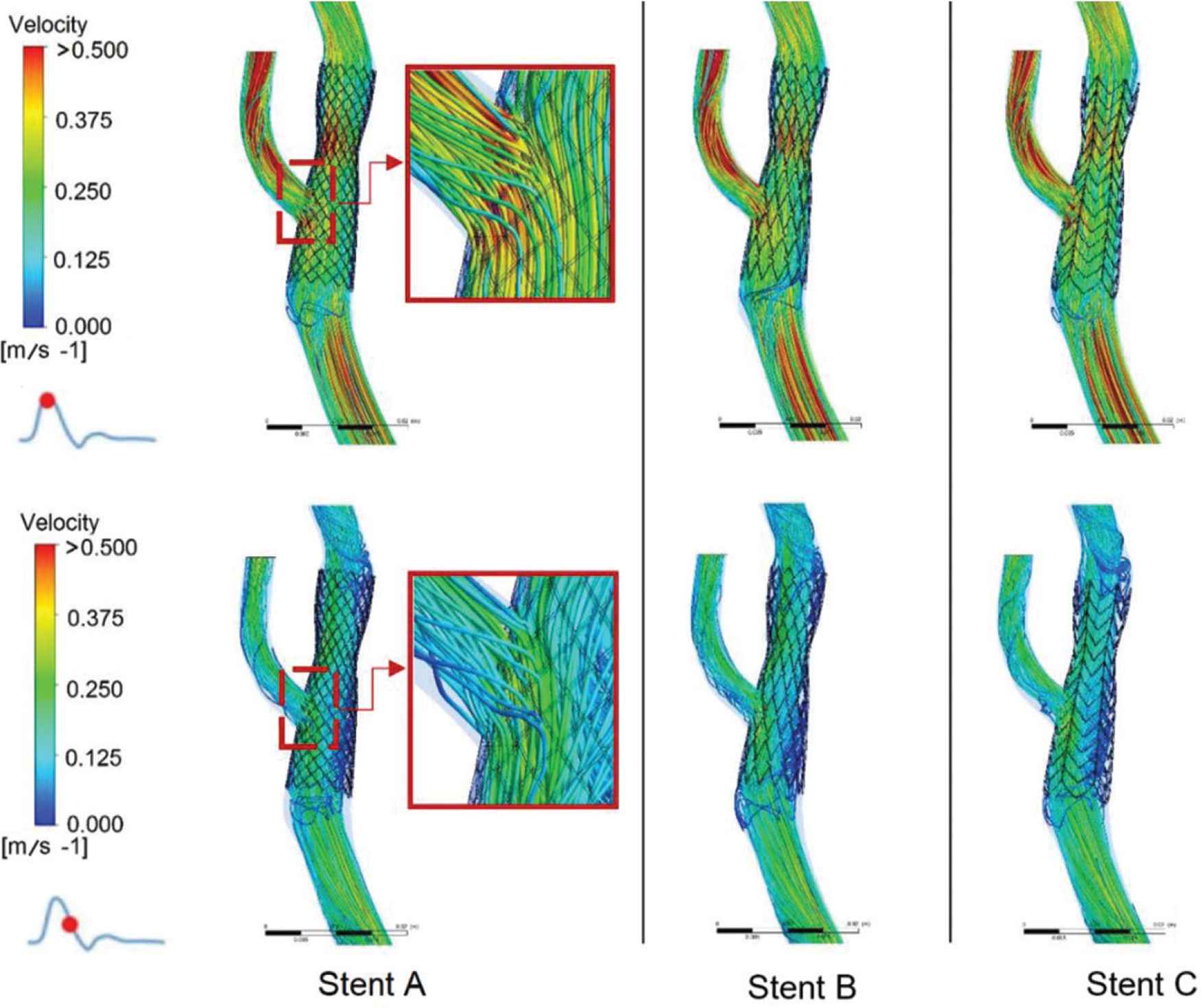
Instantaneous velocity streamline at the carotid bifurcation in all post-stent models at peak systole and maximum deceleration. The insets show the flow passing through stent struts at the ECA ostium.
Footnotes
REFERENCES
Cite this article
TY  - JOUR
AU  - Nasrul Hadi Johari
AU  - Mohamad Hamady
AU  - Xiao Yun Xu
PY  - 2020
DA  - 2020/06/07
TI  - A Computational Study of the Effect of Stent Design on Local Hemodynamic Factors at the Carotid Artery Bifurcation
JO  - Artery Research
SP  - 161
EP  - 169
VL  - 26
IS  - 3
SN  - 1876-4401
UR  - https://doi.org/10.2991/artres.k.200603.001
DO  - 10.2991/artres.k.200603.001
ID  - Johari2020
ER  -