
Development of Emotional State Model using Electromagnetic Signal Information for Rehabilitation Robot
- DOI
- 10.1080/18756891.2016.1144154How to use a DOI?
- Keywords
- electromagnetic (EM) signal; Human Machine Interaction (HMI); rehabilitation; robot-assisted platform
- Abstract
The paper presents a development of emotion recognition system which can detect human emotion in real-time leveraging information captured from human body’s electromagnetic (EM) signals. A new model of controller framework was designed to embed the emotion recognition module which was evaluated on a robot-assisted rehabilitation platform. The framework is based on hybrid automata model and used to govern the suitable trajectory to deploy by the robotic platform in assisting rehabilitation therapy. The result of the new controller design demonstrates the efficacy of the approach where emotion of the subject is taken into consideration in switching the rehabilitation tasks.
- Copyright
- © 2016. the authors. Co-published by Atlantis Press and Taylor & Francis
- Open Access
- This is an open access article under the CC BY-NC license (http://creativecommons.org/licences/by-nc/4.0/).
1. Introduction
Human Machine Interaction (HMI) is also known as Man Machine Interaction (MMI), or Human Computer Interaction (HCI). It is generally defined as a kind of interaction or communication (verbal or nonverbal) between human and machine that assist in the performance of human task. Machine is any mechanical or electrical device that transform mechanical and electrical energy into another functional form [1]. The development of HMI based applications has become a significant phenomenon in 20th century due to the interactive platform provided to govern the operation of the machines. For instance by clapping hands, a simple lighting system can be controlled more effectively. From a small home appliance to a huge production line in industry, HMI has also proven to increase the efficiency and productivity of the existing systems [2].
The idea of embodying the human emotion into health-robotic system came since research findings on emotion-health connection involving 150 thousand people from 142 countries claimed that human emotion has a direct impact on their health [3]. Hence, scientists in the field of HMI have developed robots called Socially Assistive Robots (SAR) that can understand people’s emotion and synthesize a proper response to that sentiment. In SAR, robotic systems integrate psychological aspect to achieve high quality of life through personalizing social interaction with human being [4]. The system is capable of evaluating the emotion of humans rather than only making some physical contact between them.
The needs of SAR system in recognizing human emotional state is crucial to ensure the user will have an ultimate confidence and feel comfortable in using HMI application especially for health applications such as rehabilitation robotics [5–7]. In [8, 9], NaO robot was developed with the ability to detect human emotion through body language and facial expression, reciprocate the information, before conveying different type of emotion such as anger and happiness through its robotic body.

Example of SAR: NaO robot (Adopted from [7]).
In the field of HMI, the emotion of human subject plays crucial roles in allowing the robot to react accordingly. It is reported that the impact of students’ cognitive emotions during interactions with different computer-based learning environments can be rather frustrating than boring [10]. Thus, it is essential to observe the mental health of the subject for HMI application as it could affect the self-confidence of the subject and recovery period [11] through their emotion.
A paradigm of emotion-sensitive robot for HMI is vital to lead a natural interaction between human and robot [12]. Recently, the use of robotic systems to rehabilitate disabled patients is becoming prevalent [13, 14]. This system is able to complement the manual rehabilitation technique which uses human as the therapist and has proven to be effective to a large segment of patients. The approach is capable of reducing the cost, providing efficient time management, and administering continuous monitoring in which recovery progress is also quantifiable. In addition, for post-stroke patients, under recovery, an economical rehabilitation robot is very important to be placed nearby such as at home so that they can always undergo rehabilitation exercise in the absence of human therapist.
Previous researches focus on physiological aspects of human subject and operation of the machine separately. In bridging this gap, the gate for some new research improvement is opened to increase the effectiveness of the existing system by integrating both aspects. In this research, an emotion recognizer is developed for the rehabilitation robotics application. It is envisioned that the complex task in the conventional rehabilitation process by a human therapist can be assisted by the robotic system that is naturally responsive to the emotion of the patients.
The application of HMI specifically for rehab application is not limited to the embodiment with emotion recognition system only, but it can be integrated with other system architecture as well. For instance, admittance controller was employed by Loureiro and Harwin [15] in developing a Gentle/G integrated system for robot assisted stroke rehabilitation. In the nine degree of freedom (9 DOF) system, the controller was used to adjust the speed of the DC motors for rehabilitation activity based on the measurement of the patient’s force input. Another system which was called PHYSIOBOT platform was developed to relate the psychophysiological feedback of the patient in a virtual neuro-rehabilitation task. The mechanism was controlled by a multiple input-single output Takagi-Sugeno Fuzzy logic inference system (FIS). It was operated to give several commands to the robot output which was translated into the degree of assistance in changing the spring stiffness (K) on the admittance haptic model. The input signals for the system were based on the galvanic skin response (GSR), skin temperature (SKT), and ECG data input signals from the user [16]. Another application of HMI is the novel hand rehabilitation robot named HIT-glove [17]. The system was able to assist in rehabilitating the stroke patients especially those with severe hand impairment.
The limitations of the previous HMI researches listed so far has been the absence of structured model (ie: no system model-based analysis) used to embody the emotion into rehabilitation systems. The structured model is essential for each controller to evaluate the stability and reachability of the system developed.
Overall, this paper comprises of four sections. Section 1 discusses the background of Human-Machine Interaction (HMI) applications. It justifies the need of the psychological aspect of the human subject to be programmed into the machine control system, problem related to the existing emotion recognition system and the approach taken to overcome these problems. Section 2 explains the development of emotion recognition system design. This includes the discussion on the experimental setup to induce the emotion, the verification technique, the method used to classify the dataset and the structure of hybrid automata to represent the system controller. Section 3 elaborates the results and analysis of the system followed by Section 4 that concludes the findings and some recommendations for future work.
2. System Description
The emotion recognition system for Human-Machine Interaction (HMI) specifically used for the rehabilitation robotic platform is shown in the block diagram in Figure 2 where each of the blocks is labeled and discussed in the next paragraph.
Overall block diagram of rehabilitation robot with emotion recognizer system.
2.1. Emotion Recognition System (Methodology)
In order to develop the emotional state model, an experimental setup was designed with a structured procedure to invoke the desired emotion as shown in Figure 3.
Steps in data collection for emotion modeling.
The experiment was conducted in a controlled room with 20°C. There are 21 healthy subjects randomly chosen from International Islamic University Malaysia (IIUM) Gombak and Kuantan campuses. The audio-visual materials in inducing subject’s emotion are compiled from International Affective Picture System and video sharing website [18]. The efficacy of audio-video stimuli to invoke the desired emotion has been reported in [19, 20].
Basic emotion models consist of the fundamentals human feeling namely anger, joy, sadness, surprise, boredom, disgust, and neutral [21]. Since the model is limited by a number of fundamental human emotions, the theorists had to hypothesize the mixing of the basic emotions into another type of emotion blending. The emotion blending must consist of more than one fundamental emotion as listed before. For this research, there are two fundamental emotions and only one emotion blending is being considered. The two fundamental emotions are happy (joy) and sad, while the emotion blending is nervous. Meanwhile, natural or calm emotion is being considered as a default emotion for the hybrid automata system developed. The other type of emotions is under the future study of this work. The crucial role of emotion in the control of rehabilitation system stems from the fact that current system only deals with physiological aspect of the subject [22].
The psycho-physiological aspect should make the system more adaptive and could mimic the human therapist who requires to access the emotional state of the subject before any session of rehabilitation therapy begins.
There are 3 sessions for each subject marked as ‘a’ in the Figure 3 flowchart representing 3 types of emotions under study as mentioned before. A set of electromagnetic (EM) signals from human body are recorded by using Resonant Field Imaging (RFI™) device. The efficiency of the device has been proved in [23] to classify human health condition in particular for smoker and non-smoker. In [24], there are 17 regions on human body that can be used as measuring points for determining human emotion. However, this works consider only ten of them due to the fact that the emotion recognizer is developed to be used in the robot assisted rehabilitation platform for post stroke patients specifically. These points are both left and right head, arms, palms, thighs, and forearms as denoted in Figure 4. It is then used to model the relationship between the EM signals dataset and the corresponding emotion; with calm emotion set as the default emotion for the constructed system [25].
Point of interests (POIs) for EM signal acquisition.
By utilizing Waikato Environment for Knowledge Analysis (WEKA) programming [26], the dataset is being tried on a few classifiers, for example, Attribute Selected Classifier with a precision of 70%, Decision Table (74%), Naïve Bayes (68%) and the Multilayer Perceptron with 52%. Bayes Network (BN) performed the best with the most elevated classification precision so it is chosen as the classifier with a Simple Estimator calculation in looking the contingent likelihood tables. Tenfold cross approval is chosen as the test alternative in this exploration.
The BN is fit to give reasoning under vulnerability, evaluating convictions for theory variable, and steady in joining all data from different sources [27]. The Bayesian classifier assumes the attributes to have independent distributions and the theorem for the classifier is given in Eq. (1) and Eq. (2).
di is the features (10 points EM signals),
cj is the class (emotion),
- i
=1:10
- j
=1:3
- p(c|d)
= probability of instance d being in class c,
- p(d|c)
= probability of generating instance d given class,
- p(c)
= probability of occurrence of class c
- p(d)
= probability of instance d occurring
From the experiment, the result shows that the system is able to recognize the right emotion at the rate of 90% accuracy and 80.6% precision by using Bayesian Network classifier.
The GUI provides a display and a manual input as illustrated in Figure 5. It can only provide parameters for the control system and cannot perform any automatic coding. To use the GUI, the user has to be defined and the set of 10 EM signal values have to be keyed in. The trained BN classifier is then executed to classify the emotion. The emotion s then coded into value that is later passed to the hybrid automata system to control the rehabilitation robotic platform.
Graphical User Interface (GUI) for displaying appropriate emotion.
As the last step, the new coded dataset value is customized into the chosen classifiers before the matching identical emotion and its relating hybrid automata code are shown as the yield. The hybrid automata code is the coded value that is passed from GUI to Stateflow to administer the rate or speed, and the direction of the end-effector of the rehabilitation robotic platform. For instance, Code 1 shows that the subject is in sad feeling. On the off chance that the client is in nervous feeling, Code 2 is shown while Code 3 is assigned for happy feeling. A default feeling which is calm is marked as code 0. “Reset” catch is utilized to initialize the EM signal values at all POI to be zero.
In confirming the emotion prompted during the experimental session, toward the end of every varying audio-visual session, the subject is given an arrangement of questionnaire [28]. The questionnaire is made out of 2 sections which are demographic information of the subject and a Likert Scale of 4 for every video session. Details of the questionnaire can be found in Figure 6.
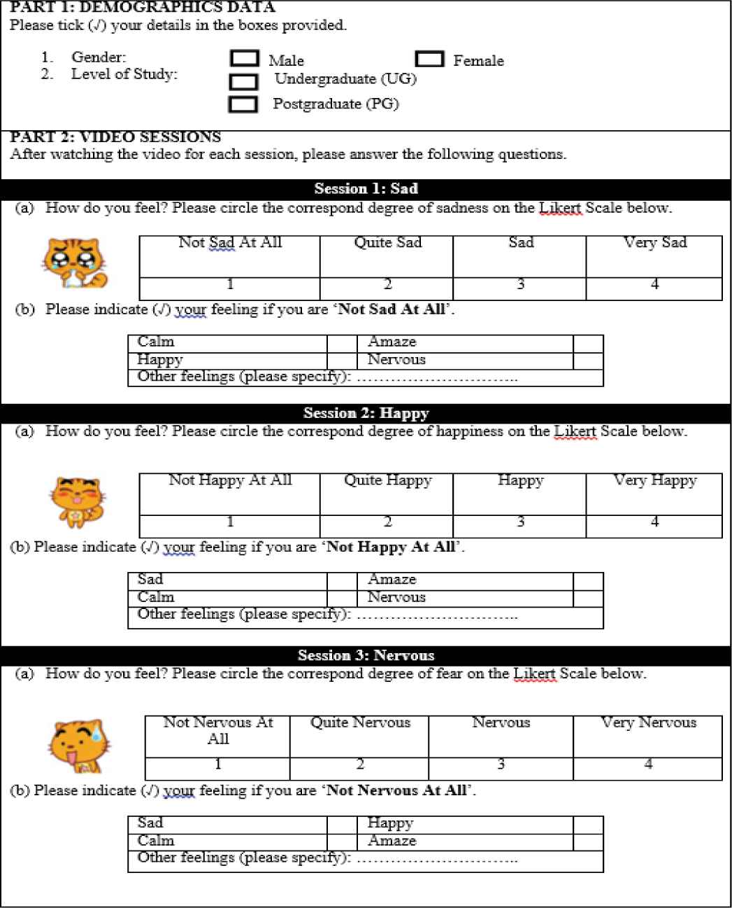
Questionnaire to verify the subject’s emotion
2.2. Robotic Platform
In embedding the emotion into Human Machine Interaction applications, an upper extremity rehabilitation robot is utilized to test the system via hybrid automata as the control system. There are four major parts of the rehabilitation robotic platform system consisting of rotational axis actuator, linear guide or locking mechanism, linear guide actuator, and gripper as depicted in Figure 7 [25].
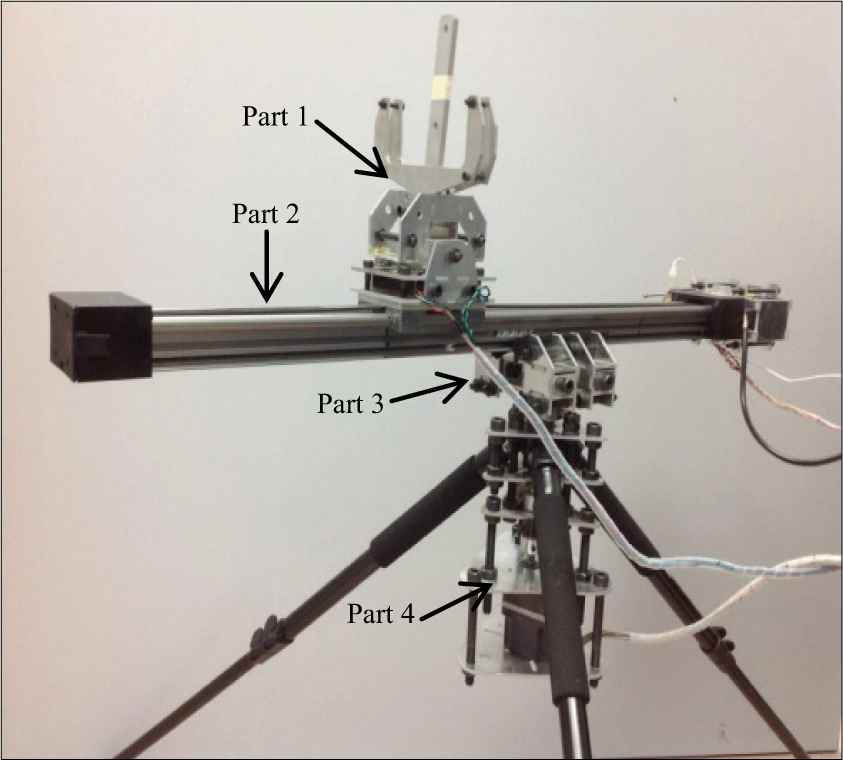
The robot assisted rehabilitation platform.
The affected subject’s arm is put on the platform then the linear actuator help the movement of the arm forward and backward repeatedly by using brushless DC motor. Impact of stroke generally shows up on one side of the body where amid the rehabilitation method of the influenced limb (i.e. arm), the unaffected one is held constraint. The system of the rehabilitation treatment through arm movement is appeared in Figure 8.
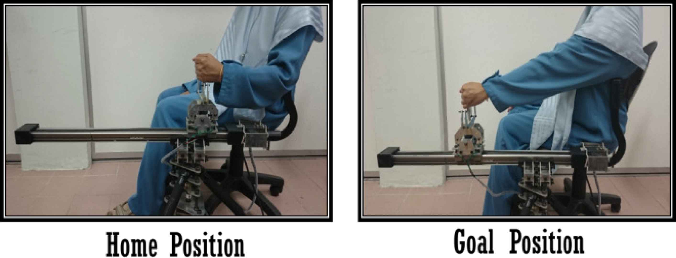
Demonstration of the affected arm’s movement during treatment.
2.3. Controller Modality: DES
Figure 9 illustrates the block diagram of emotion recognition system embodiment into the rehabilitation robotic platform via hybrid automata system [29].
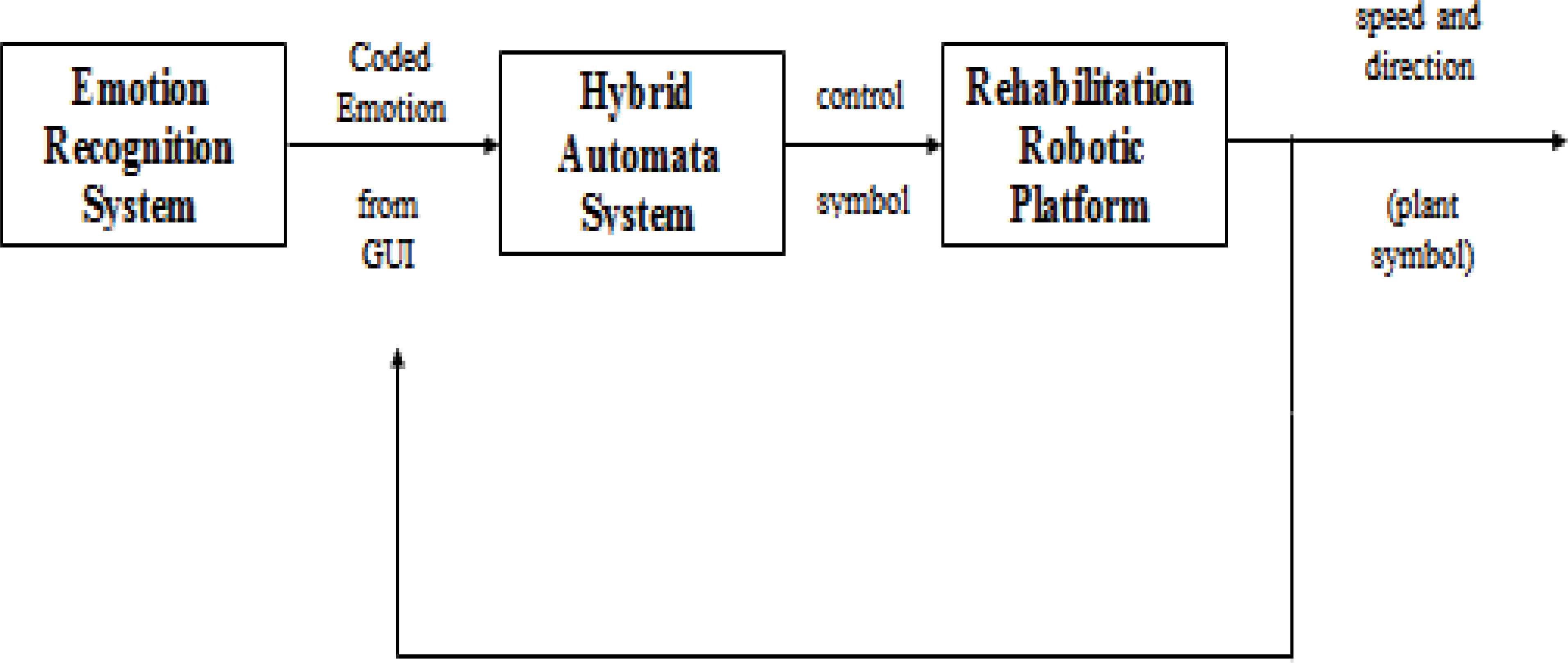
Emotion embodiment into rehabilitation robotic platform
The output from the emotion recognizer is being classified and coded by GUI before the hybrid automata system use the coded emotion to give several commands to the robotic platform in controlling the speed and direction of the gripper movement. Si/ri represents the state and the control symbol for each mode and xi represents the plant symbol of the system.
The controller modality for the robotic platform is Discrete Event System (DES) as elaborated in Figure 10.
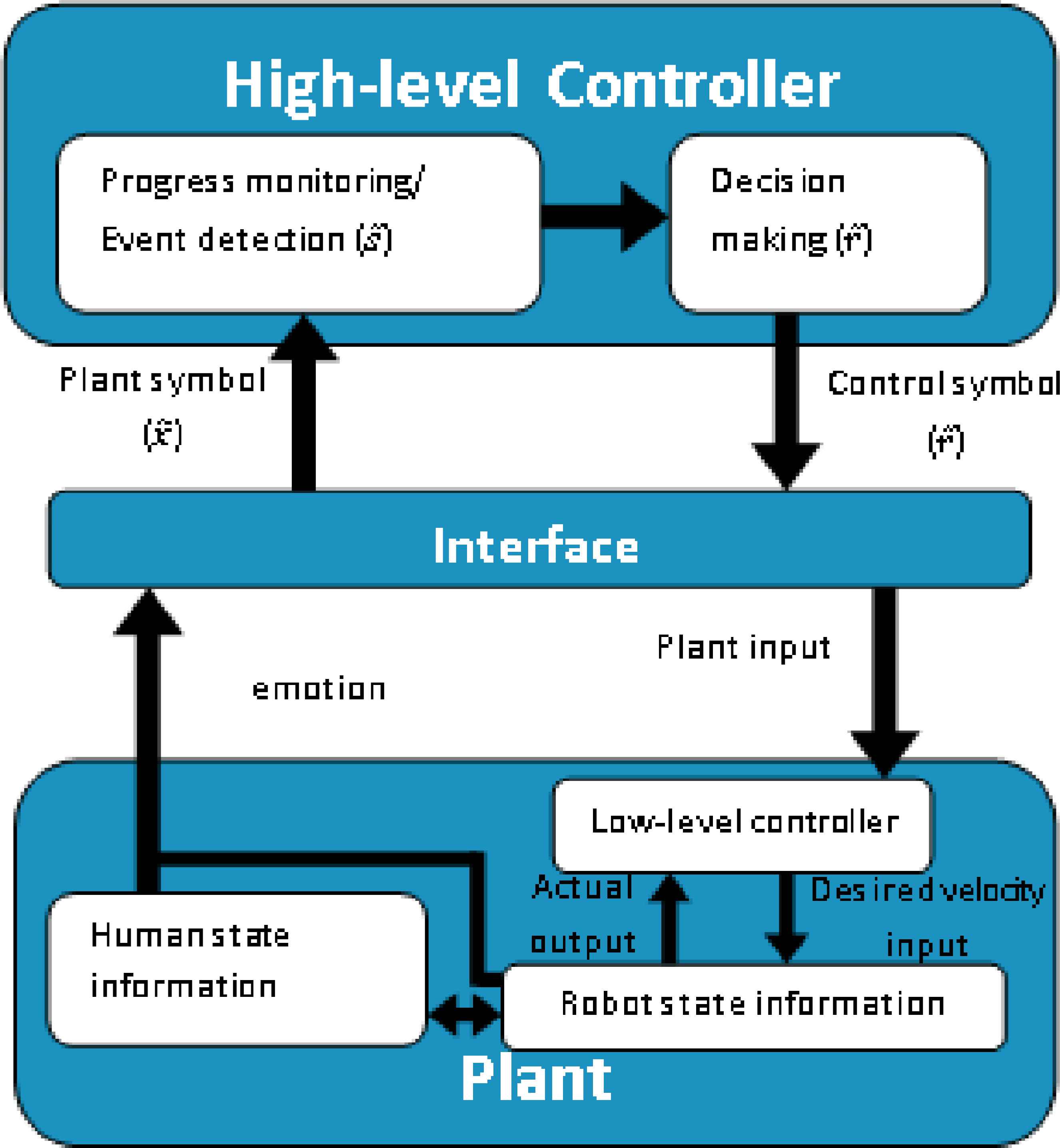
Controller modality for robotic platform with emotion embodiment.
The controller developed for this project is divided into 3 major parts which are high level controller, interface, and low level controller (plant). The high level controller is designed to control the designated discrete input-output while the low level controller in plant is used to handle the continuous input-output to the robotic platform. The interface used to interchange both discrete and continuous element in the DES is the robotic platform, through its ability in changing the speed and direction of the gripper based on emotion detected.
For the developed system, the input-output discrete elements are the emotion of the subject and the control state commands via hybrid automata system whereas, the speed and position of the gripper movement is labelled as input-output continuous elements [30].
A set of the discrete inputs for the hybrid automata model is the EM signals from the POI which are eventually classified into particular emotions while the continuous input is the desired speed of the rehabilitation platform. The basic representation of the hybrid automata model of the system is shown in Figure 11 where S1 represents the initial state. The automata can be described in 6-tuple as follows;
- (i)
Control states,
- (ii)
Plant symbol,
- (iii)
Control symbol,
- (iv)
Transition function,
- (v)
Initial state, X0= {S1}
- (vi)
Final state, Xm= {Si}
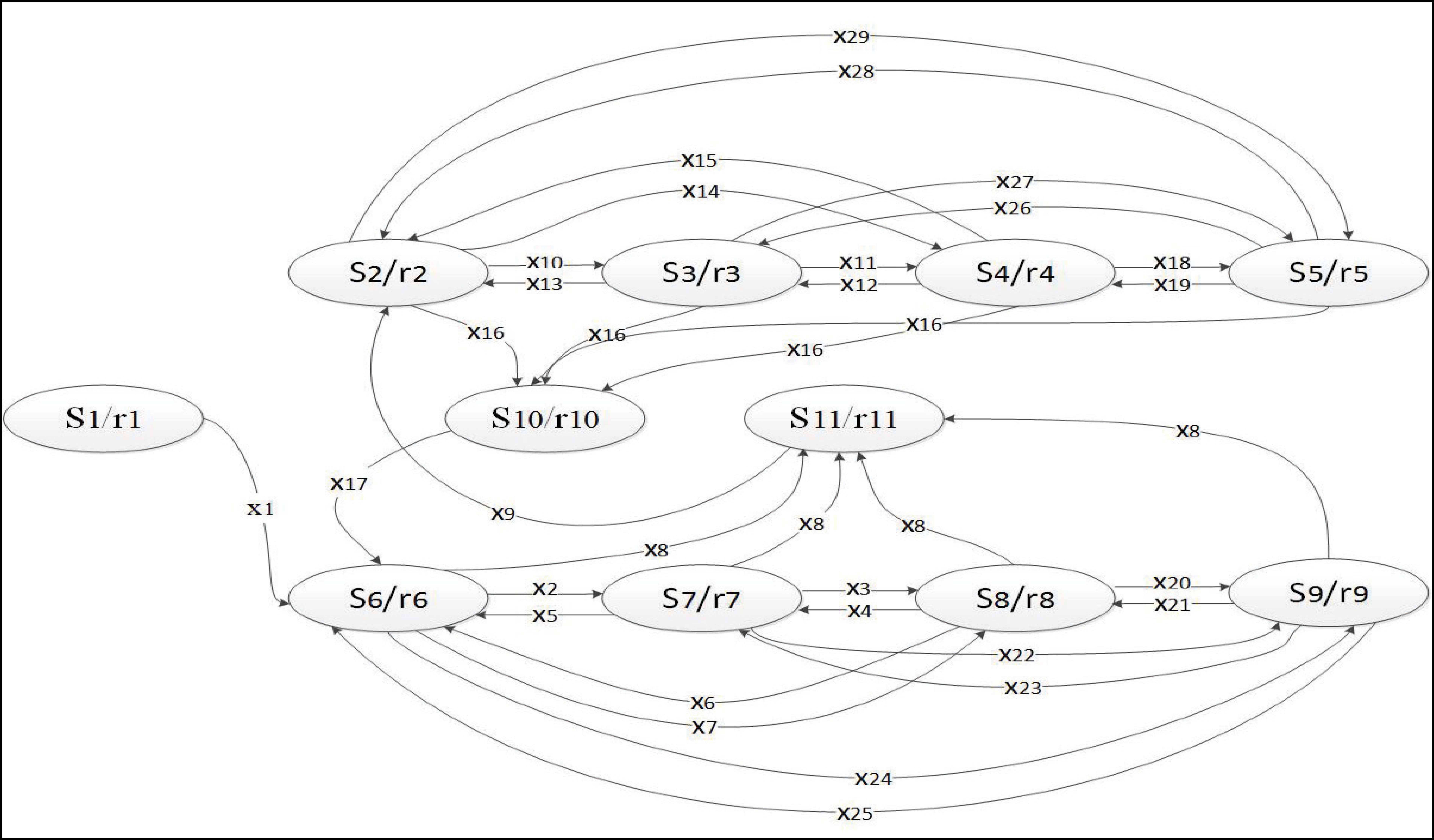
Hybrid automata model.
Two types of symbols are used in the hybrid automata which are plant symbol and control symbol. These symbols are employed to represent the task assigned to the rehabilitation platform in changing the speed and direction of the gripper based on the emotion of the subject. There are eleven control states or modes described for the rehabilitation platform. Each of the modes represents the dynamic evolution of the system (i.e. speed, direction, and subject emotion) given different desired speeds and directions to follow during the rehabilitation session. The transition between modes is allowed once the guard condition (i.e the type of emotional state) is fulfilled.
The continuous set of platform dynamics is governed by the discrete type of emotion. The intention in controlling the speed and direction of the platform movement is to mimic the human therapist in changing the rehabilitation tasks based on the emotional state of the patient. Thus, the system is able to act more naturally in autonomous form.
The input to the system is the emotion, E. The position of the gripper, X(m) is acquired from the potentiometer reading, from which speed, ν of the gripper (cm/s) and the direction, dir of the gripper movement are derived. The wanted speed that is set for the gripper to move relies on upon the automaton that is activated by the separate feeling. It is expected that the subject is at default state when he/she is “calm” with a set speed of 0.833cm/s. For the other emotional states the speed is set appropriately. For instance, the most extreme speed of the platform is set when the subject is happy, since the patient could give greatest attention regarding the rehabilitation session whereas the base speed of the gripper is set when the subject is sad. For this emotional state, the subject may give practically zero concentration throughout the rehabilitation therapy session. The moderate speed is set if the subject is nervous in which case the subject give partial attention for the rehabilitation session.
The operation of the system is described by different tasks in which the linear actuator or gripper moves at different speeds and directions when the affected arm is under rehabilitation session. In describing the hybrid automata model, the control symbols or conditions of the modes, control states or modes, and plant symbols of the system are initialized in Table 1 to Table 3.
| Control State | Platform Modes |
|---|---|
| State 1 (S1) | Initial |
| State 2 (S2) | Intro Mode Back |
| State 3 (S3) | Excited Mode Back |
| State 4 (S4) | Advance Mode Back |
| State 5 (S5) | Rilex Mode Back |
| State 6 (S6) | Intro Mode Forth |
| State 7 (S7) | Excited Mode Forth |
| State 8 (S8) | Advance Mode Forth |
| State 9 (S9) | Rilex Mode Forth |
| State 10 (S10) | End Forth |
| State 11 (S11) | End Back |
List of Control States and Platform Modes
| Control Symbol | Task Assigned |
|---|---|
| r1 | The gripper moves backward to home position (X=20) with maximum speed of 1cm/s |
| r2 | Subject is sad (speed:0.5cm/s and direction : backward) |
| r3 | Subject is nervous (speed:0.667cm/s and direction: backward) |
| r4 | Subject is happy (speed:1.0cm/s and direction: backward) |
| r5 | Subject is calm (speed:0.833cm/s and direction: backward) |
| r6 | Subject is sad (speed:0.5cm/s and direction: forward) |
| r7 | Subject is nervous (speed:0.667cm/s and direction: forward) |
| r8 | Subject is happy (speed:1.0cm/s and direction: forward) |
| r9 | Subject is calm (speed:0.833cm/s and direction: forward) |
| r10 | Negate dir value (change direction from forward to backward with minimum speed: 0.333cm/s) |
| r11 | Negate dir value (change direction from backward to forward with minimum speed: 0.333cm/s) |
List of Control Symbols and Task Assigned
| Plant Symbol | Type of Emotion and Gripper position (X in cm) |
|---|---|
| x1 | Gripper at goal position (X=20) |
| x2 | Subject emotion change from sad to nervous AND (X=5) |
| x3 | Subject emotion change from nervous to happy AND (X=5) |
| x4 | Subject emotion change from happy to nervous AND (X=5) |
| x5 | Subject emotion change from nervous to sad AND (X=5) |
| x6 | Subject emotion change from happy to sad AND (X>=5) |
| x7 | Subject emotion change from sad to happy AND (X>=5) |
| x8 | Gripper at goal position (X=5) |
| x9 | Gripper direction changes from forward to backward (5<X<6) |
| x10 | Subject emotion change from sad to nervous AND (X<=20) |
| x11 | Subject emotion change from nervous to happy AND (X<=20) |
| x12 | Subject emotion change from happy to nervous AND (X<=20) |
| x13 | Subject emotion change from nervous to sad AND (X<=20) |
| x14 | Subject emotion change from sad to happy AND (X<=20) |
| x15 | Subject emotion change from happy to sad AND (X<=20) |
| x16 | Gripper at home position (X=20) |
| x17 | Gripper direction changes from backward to forward (19<X<20) |
| x18 | Subject emotion change from happy to calm AND (X<=20) |
| x19 | Subject emotion change from calm to happy AND (X<=20) |
| x20 | Subject emotion change from happy to calm AND (X=5) |
| ‘x21 | Subject emotion change from calm to happy AND (X=5) |
| x22 | Subject emotion change from nervous to calm AND (X=5) |
| x23 | Subject emotion change from calm to nervous AND (X=5) |
| x24 | Subject emotion change from sad to calm AND (X=5) |
| x25 | Subject emotion change from calm to sad AND (X=5) |
| x26 | Subject emotion change from calm to nervous AND (X<=20) |
| x27 | Subject emotion change from nervous to calm AND (X<=20) |
| x28 | Subject emotion change from calm to sad AND (X<=20) |
| x29 | Subject emotion change from sad to calm AND (X<=20) |
List of Plant Symbols and Definitions
The sets of control states which represent the patient’s emotion and direction of the gripper movement is presented in Table 1.
S10 and S11 denote the control state that the patient arm has reached the home and goal position in the rehabilitation trajectory. For example, in the initial state, S1 the gripper moves backward until it reached the home position at X=20 with the speed of 1cm/s from any previously rest position. The gripper then moves forward to the goal position located at X=5 with different speed based on the emotional state detected. The speed is set to decrease whenever the gripper is nearly to the end point in order to reduce the momentum before the gripper switches direction as depicted by S10 and S11. The robotic platform’s operation continues until a stop command is sent to the system. Each of the control symbols, r produce a unique rehabilitation treatment that mends to symbolize the different type of task assigned as listed in Table 2. The tasks assigned are different in terms of speed of the gripper’s movement solely based on the subject emotion.
The plant symbols listed in Table 3 are generated based on the information from position sensor (potentiometer) of the robotic platform and the emotion of the subject. It represents the possible evolution of system dynamics which is speed and direction of the gripper besides the subject emotion. The plant symbols will change from one plant symbol to another plant symbol only if it fulfills the requirement of the guard condition of the hybrid automata model. It then becomes the precondition before the transition between one control state to another control state can occur [31].
3. Results and Discussions
In order to study the efficacy and the performance of the hybrid automata system, different case studies are designed to reflect possible events that might occur in the real setup.
3.1. Case Study 1: Offline Simulation with Simulated Inputs
In the case studied, an offline simulation is conducted to analyze the functionality of the hybrid automata. A series of emotional states is set as the input to the hybrid automata system in ‘Repeating Sequence Stair’ form as shown in Eq. (3);
The period for each emotion state is fixed to 10s as correlated to a finding which claims that emotion is very brief in duration and can change in several seconds [32]. Figure 12 shows the result from the simulation. The subject is sad from point A to point B during a particular rehabilitation therapy. Since the location of the gripper is not reaching the home position (X=20), the speed of the gripper is set to 1cm/s with the backward motion until it reaches point C. The speed is set intentionally as part of the calibration process.
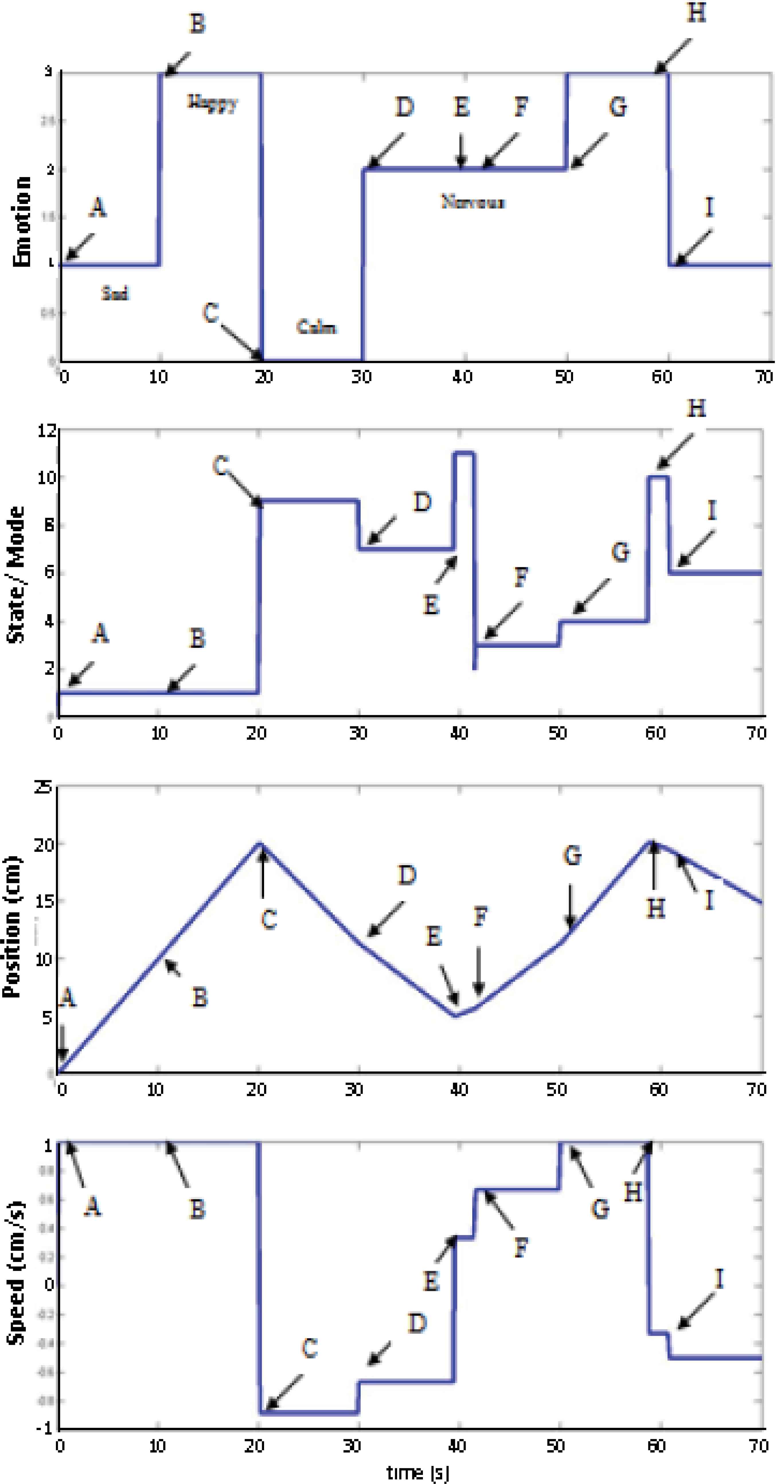
Simulation of emotion, state, position, and speed profiles for Case Study 1.
Thus the emotion detected during this time is ignored (i.e. state=S1). Point C shows that the subject has reached the home position and switches the gripper direction from backward to forward motion with calm emotion (E=0).
The speed is set to -0.883cm/s and the active state is S9. While performing the task, it is observed that the subject has shown a change in the emotion to nervous (E=2) at point D, thus the speed is adjusted to - 0.667cm/s and S7 becomes the active state. At point E, the goal position (X=5cm) is reached to prepare the gripper to negate its motion into backward direction. Thus the state switches to S11 to adjust the minimum speed value to 0.333cm/s in order to reduce the impact of gripper’s direction changing and some ‘cushion’ on the drastic change in the direction. At point F, the emotion remains nervous (E=2). Without delaying, the state switch to S3 and the speed changes to 0.667cm/s. Up to point G, the emotion detected is happy (E=3) and this causes the state to switch to S4, thus increases the gripper speed to 1.0cm/s. As it reaches the home position which is at X=20cm, the state S10 is activated, thus negates the direction and sets the new speed to - 0.333cm/s as can be seen at point H. When the point I is reached, the state profile is automatically changed to S6 and the speed is set to -0.5cm/s in the forward motion (E=1).
The case study proves that the developed hybrid automata system works perfectly in the simulation environment. The control framework is flexible and effective enough to allow additional or deletion of any state without the needs to redo major reprogramming.
3.2. Offline Experimentation with Simulated Inputs
For case study 2, the same automata developed in case study 1 is tested to analyze the adaptability of the rehabilitation platform with the hybrid automata developed. The sequence of emotion is given in ‘Repeating Sequence Stair’ form as shown in Eq. (4);
The period for each emotion state is fixed to 10s. Figure 13 captures the dynamics evolution between the emotion, the system state, position and speed of the system. For the first ten seconds, which is from point A to B, the emotion of the subject is denoted as 3 to indicate happy emotion. However, regardless of emotion, since the system is initializing, the gripper is moving backward to home position at X=20 from the previous resting position, with speed of 1.0cm/s. As the gripper reaches the home position at point B for the first time, the emotion is still happy (E=3), but the state is now switched to S8 to prepare the gripper to move forward at speed of -1.0cm/s.
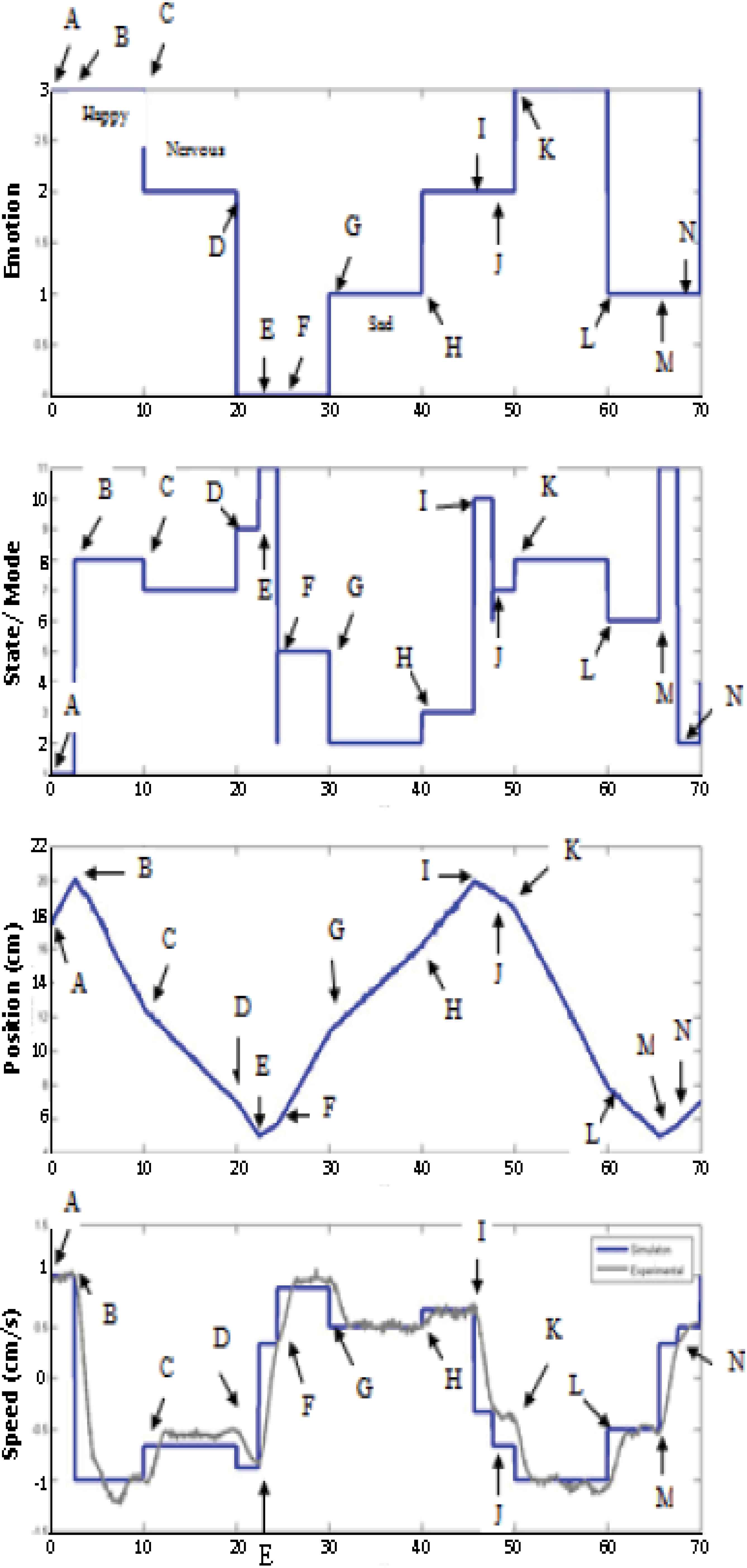
Simulation of emotion, state, position, and speed profiles for Case Study 2.
At point C while moving forward, the emotion is switched to nervous (E=2), thus the state switches to S7 and the speed is made slower to -0.667cm/s. At point D, the emotion switches to calm (E=0), prompting the state to switch to S9 and the speed to -0.883cm/s while the gripper is still moving forward until goal position. At point E, the goal position is reached so the state switches to S11 to negate the speed value. In order to cushion the drastic change in the direction, the speed for this state is set to 0.333cm/s (the minimum speed). Now the gripper is moving backward to home position. At point F, the emotion detected is still calm (E=0) and this causes the state to switch to S5, thus changing the speed to 0.833cm/s.
The state remains the same until at point G; the emotion detected changes to sad (E=1). It causes the speed and state changes to 0.5cm/s and S2 respectively. At point H, the speed switches to 0.667cm/s indicates the input emotion is nervous (E=2). It continues until the home position is reached. As it reaches the position, the state S10 is activated, thus negates the direction and sets the new speed of -0.333cm/s as can be seen at point I. At point J, the state switches to S7 denoting the emotion detected is still nervous (E=2) and the speed of the gripper is set to -0.667cm/s.
At point K, the emotion changes to happy (E=3). Without delaying, the state switch to S8 and the speed changes to -1.0cm/s. At point L, the emotion detected is sad (E=1) and this causes the state to switch to S6, thus increases the gripper speed to -0.5cm/s. At point M, the goal position is reached to prepare the gripper to move backward. So the state switches to S11 to negate the speed value of 0.333cm/s. Finally at point N, S2 is activated (E=1) and the speed of the gripper is set to 0.5cm/s.
From the graph in Figure 13, the system is able to track the change of emotion and position of the gripper, and react accordingly by changing the corresponding state and speed of the system. Figure 14 shows the speed error between the simulated and experimented case study.
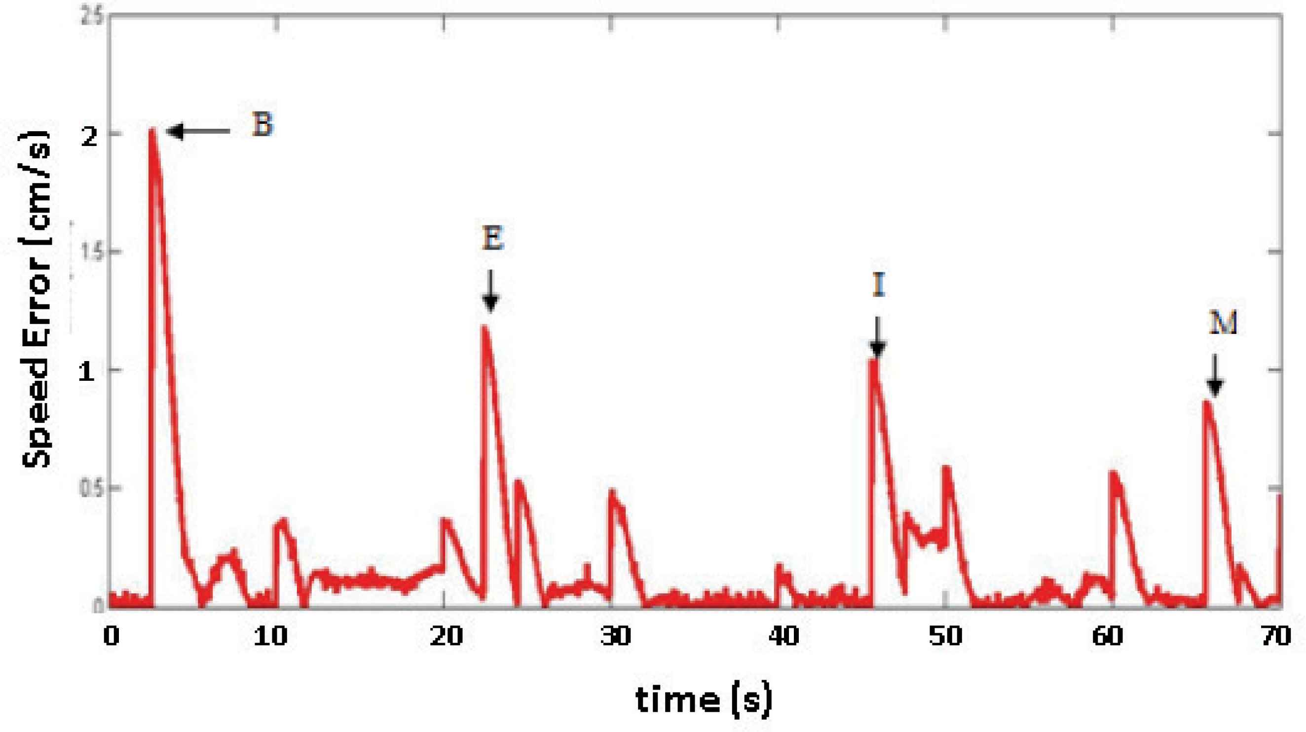
Error generated by the rehabilitation platform.
It can be seen the peak errors occur at the points where the direction of gripper changes due to the mechanism of the robot in changing the gripper’s speed on time via the hybrid automata’. The experimental and simulation results verify that the hybrid automata approach is practical for the Human Machine Interaction in rehabilitation applications.
3.3. Online Simulation vs Experimentation with Real Time Inputs
In case study 3, the rehabilitation system takes the emotional state input in real time. Instead of using ‘Repeating Sequence Stair’ as an array of the input emotions, a constant block called ‘emot’ is utilized in integrating the Simulink-Stateflow with rehabilitation platform and the Graphical User Interface (GUI) to infer the emotion of the subject. The function of ‘emot’ block is to set the hybrid automata input which is directly taken from the ‘hybrid automata code’ in GUI.
In this case, the initial emotion of the subject is sad (E=1) at the beginning of the therapy. The emotion of the subject converges from sad to nervous, nervous to calm, then back to nervous again before ends with happy emotion.
When the task execution starts, S1 is triggered since the Stateflow is in initialization mode. The gripper is in backward motion with the desired speed of 1cm/s at point A as seen in Figure 15. When the subject’s arm has reached the home position (X=20cm) at point B, S6 activated to guide the patient arm’s movement in forward motion. Simultaneously, the desired speed is decreased to -0.5cm/s. At point C, the gripper speed is set at -0.667cm/s and the active state is S7. As the gripper reaches the goal position (X=5cm) at point D for the first time, the emotion detected is still nervous (E=2), but the state is now switched to S11 to prepare the gripper to move backward at speed of 0.333cm/s. At point E, the emotion remains at nervous (E=2), prompting the state to switch to S3 and the speed to 0.667cm/s.
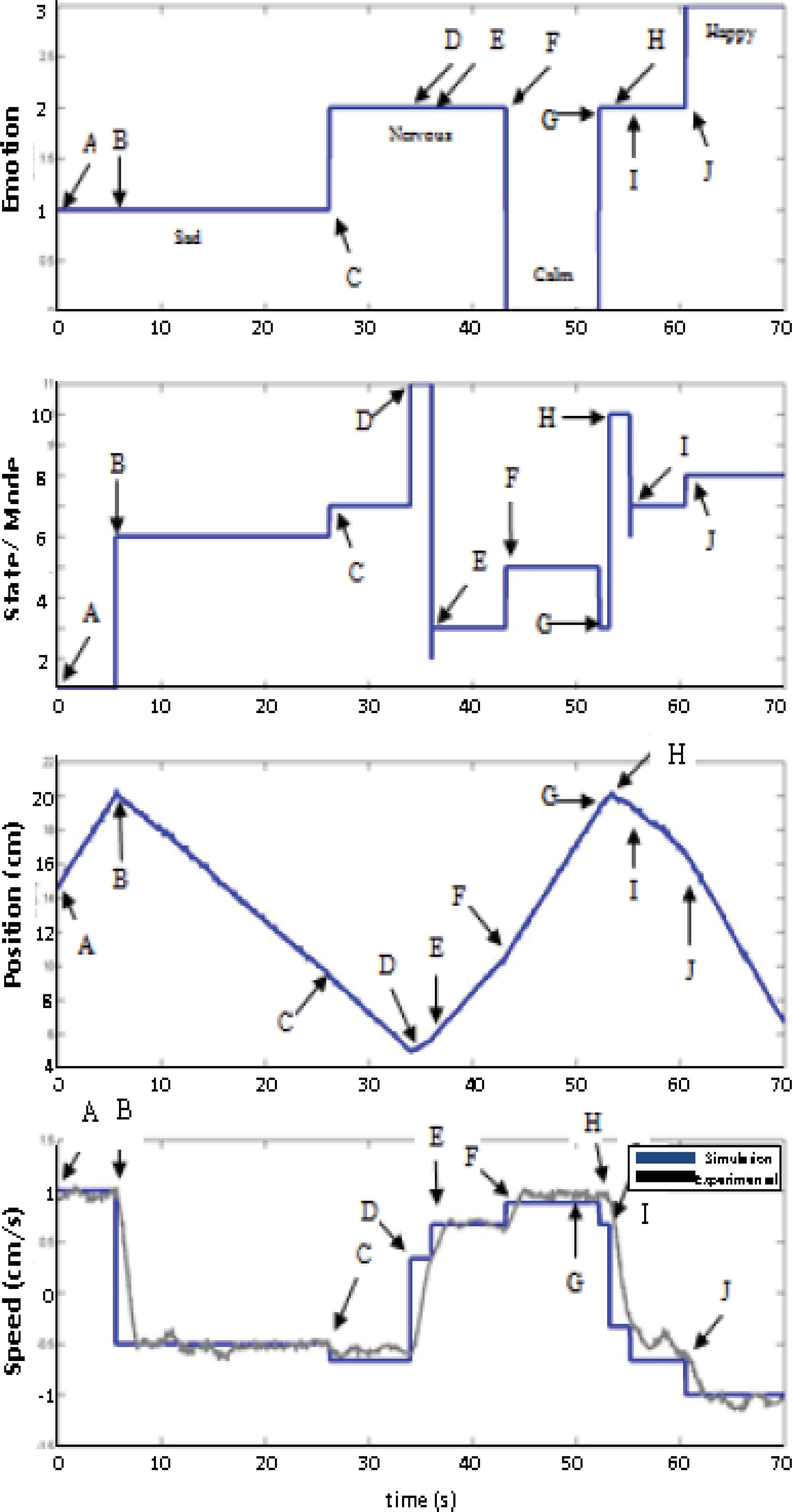
Simulation of emotion, state, position, and speed profiles for Case Study 3.
While performing the task, it is observed that the subject has shown a change in the emotion to nervous (E=0) at point F, thus the speed adapts the changes to 0.883cm/s and S5 becomes the active state. At point G, the state switches to S3 denoting the emotion detected is still nervous (E=2) and the speed of the gripper is set to 0.667cm/s. At point H, the speed changes to a negative value of -0.333cm/s which is in S10. It symbolizes that the subject’s arm has reached the home position and the gripper direction is changed to forward motion again. At point I, the state switches to S7 denoting the emotion detected is still nervous (E=2) thus the gripper changes the direction and the speed is set to 0.667cm/s. The subject is finally observed to be happy (E=3) in performing the task due to change of state as can be seen at point J. It activates S8 with the speed of -1.0cm/s.
4. Conclusions
The hybrid automata system is chosen as a framework to embody three types of emotions which are happy, sad, and nervous as classified by the emotion recognition system in controlling the rehabilitation robot platform. Three different scenarios are run to test the workability of the embodiment system through offline and online modes. The experimentation and simulation results verify that the hybrid automata approach is practically feasible for the Human Machine Interaction in rehabilitation applications. Some future works to improve the efficacy of the technique is suggested such as to deploy ANOVA test to discriminate the input points that are correlated. The embodiment of emotion recognition system into rehabilitation robotic platform also can be automated by using other technique such as decision tree, petri net, and fuzzy logic approach in order to compare the performance of the new system with hybrid automata approach.
Acknowledgements
The work presented was carried out in the Biomechatronics Research Laboratory of International Islamic University Malaysia. The authors wish to acknowledge the subjects who took part in this project and grant funding from the Ministry of Higher Education Malaysia (RAGS 12-002-0002).
References
Cite this article
TY  - JOUR
AU  - Aimi Shazwani Ghazali
AU  - Shahrul Naim Sidek
AU  - Sado Fatai
PY  - 2016
DA  - 2016/01/01
TI  - Development of Emotional State Model using Electromagnetic Signal Information for Rehabilitation Robot
JO  - International Journal of Computational Intelligence Systems
SP  - 65
EP  - 79
VL  - 9
IS  - 1
SN  - 1875-6883
UR  - https://doi.org/10.1080/18756891.2016.1144154
DO  - 10.1080/18756891.2016.1144154
ID  - Ghazali2016
ER  -