
Fuzzy Based Reconfiguration Method Using Intelligent Partial Shadow Detection in PV Arrays*
- DOI
- 10.1080/18756891.2016.1150004How to use a DOI?
- Keywords
- PV Arrays; Shadow Detection; Reconfiguration; Partial Shading Diagnosis; Fuzzy Logic; Switching Matrix
- Abstract
Photovoltaic (PV) systems are the most commonly used methods. PV systems have the most potential and efficiency between the species of renewable energy. However, this method can be subjected to a loss of energy gain when shading occurs on the PV panels. To overcome this negative situation, a reconfiguration process in the PV systems has been developed. Through this method, the power losses caused by the shading of the panel on the system are attempting to be minimized . Without any change in the physical location of the pre-shading panels, the panels are co nfigured with electrical connectors. In this study, a new efficient and intelligent reconfiguration method is proposed. The short-circuit current values of the PV panels are detected using current sensors. Short-circuit current values vary in proportion to the shadings that occur on the panels. A fuzzy calculation is carried out taking the current values into account as the system input parameters. The optimal connection structure is detected by using the fuzzy output values. The result is then applied to the system by switching the matrix circuit. The proposed method has been tested in different shadowing conditions and has been seen as a gain ratio. Experiments performed in real-time availability have confirmed the suitability of the method for different sized systems.
- Copyright
- © 2016. the authors. Co-published by Atlantis Press and Taylor & Francis
- Open Access
- This is an open access article under the CC BY-NC license (http://creativecommons.org/licences/by-nc/4.0/).
1. Introduction
Nowadays, the amount of non-renewable energy sources demand and rising fuel prices have led to a turn to renewable energy sources. Hence, researchers are working to produce energy using renewable natural resources. In this way, they are aiming to meet the growing energy demand, be environmentally friendly and reduce the cost. One of the most appropriate renewable energy sources is solar energy. Electrical energy is obtained by converting solar radiation in PV systems. While obtaining this type of energy, some disadvantaged situations may occur (e.g., partial shading may occur in PV arrays because of clouds, birds, trees or contamination) and the solar radiation received by a PV panel can drop in value . As such, the amount of power given by a panel decreases because of the shading1. Two methods have been developed to overcome the negative effects of shading: maximum power point tracking (MPPT) and reconfiguration2. In the MPPT approach, the main aim is tracking the maximum power point on a PV curve that is obtained by using the present system values (e.g. current, voltage and power). However, the applicability of this method is not appropriate for all PV arrays and it is the only system-specific working method3,4,5,6,7,8,9,10. This approach is also unable to provide sufficient efficiency, as it cannot obtain sufficient power and takes so much time.
In the second approach, the reconfiguration aims to find the best connection structure that obtains the maximum power point in the PV system. The reconfiguration process uses a fixed panel, an adaptive panel and a switching matrix circuit. The system provides the opportunity to work with a dynamic structure11. Many studies have investigated the reconfiguration12,13,14,15. In some of these studies, in the reconfiguration process, mathematical calculations and various input parameters are used. The reconfiguration process proposed by Liu et al.12 is shown in Fig. 1. In this study, the voltage and current values taken from the panels are used. El-Dein et al.13 calculated the index value of the radiation level compliance. These methods are difficult and time-consuming because of the calculation complexity and the need for extra calculations.
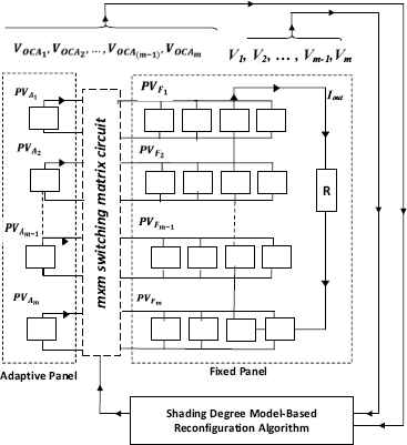
Reconfiguration process12.
In some of the reconfiguration methods, changes associated with the electrical structure of the PV cell have been proposed. In such methods, the hardware used in system made the system more complex. As such, there was a reduced efficiency in obtaining the values of these elements in the reconfiguration process. Velasco et al.15 used the EAR (Electrical Array Reconfiguration) approach and proposed a mathematical expression to minimize the difference between the radiation levels on the arrays by using the switches. In another study dealing with radiation values of PV arrays16, a reconfiguration is provided by the Su Do Ku method. Su Do Ku is a method designed by assigning logical values to PV arrays. It aims to obtain the maximum power from the system in cases of partial shading without making any changes in the electrical connections of the PV arrays. The shading values are distributed to different regions to get the same radiation on the same sub-modules.
While the proposed approaches can be applied to small sized systems, they cannot be applied to large sized systems.17 calculated all of the possible connections for arrays and found the best one among them. However, the permutations and sorting operations used negatively affected the performance of the system. In another study18, the bubble sort algorithm was used. When this method is applied in large sized systems, the process time will be increased, even though it had an efficiency in small sized systems. In Nyugen et al.19, two methods were proposed to find the maximum power from the arrays. Experimental operations were applied for a small sized PV system. When we consider this approach for more PV arrays, it will take more running time.
Reconfiguration is a method that is developed to increase the output power of a PV system that decreased in the case of partial shading. This method mainly consists of basic blocks: fixed panel, adaptive panel and a switching matrix circuit. The fixed panel has more PV cells and is the main part of the system. It is structured with one of the connection types of the S&P (Series-Parallel), TCT (Total-Cross Tied) and BL (Bridge-Linked), as illustrated in Fig. 2. It does not undergo any changes during the process and is always fixed. The first part, the fixed PV panel part, consists of mxn PV panels (m sub-modules, consisting of n cells). The arrays in the fixed panels are F1, F2,…, Fm. The second main part, the adaptive panel, consists of an m PV panel, A1, A2,…, Am. There is also a switching matrix circuit that provides the connection between the adaptive panel and the fixed panel. As illustrated in Fig. 3, each switch in this circuit is designed, as any PV array in an adaptive panel will be connected to an array in the fixed panel.
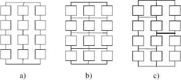
Connection type of fixed panel a) S&P b) TCT c) BL
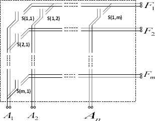
Switching matrix circuit
The reconfiguration approach is aimed at determining the best connection structure that provides the maximum power for the system by the processing values from the adaptive and fixed panels. The obtained connection information is applied to the system by a switching matrix circuit. The PV system will become the dynamic mode of the operation with this method. A graphic that shows the power efficiency obtained with the reconfiguration method is illustrated in Fig. 4.
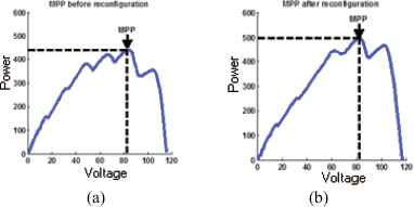
MPP variation for a reconfiguration in the same PV array
In this study, a fuzzy partitioning based artificial approach for a reconfiguration in PV arrays has been proposed. For the fixed panel structure, a TCT connection type is used. The proposed algorithm takes the radiation and current values from the adaptive panel and the fixed panel as input parameters. The detected values are transmitted to a control and decision unit after processing the fuzzy calculations. The results taken from the unit are sent to the switching matrix circuit. The system has the optimum connection structure to obtain the maximum power. Large and small sized PV systems both have short reply times with this algorithm. In addition, the system will work at the maximum power point.
2. Proposed Approach
The reconfiguration is an important method for providing the maximum performance on a PV system. In performing the method, a major step is determining the optimal connection structure. This step should be as accurate and as quick as possible, especially in large sized systems. In this study, a very efficient algorithm that can be applied to real time systems is proposed. The algorithm has a fuzzy partitioning based artificial approach. The short circuit currents obtained from the adaptive and fixed panels (Isc) are transmitted to a fuzzy control unit. Here, the fuzzy partitioning operation is done. The optimal connection structure is then determined and the result is applied to the arrays by the switching matrix circuit. A block diagram illustrating proposed approach is given in Fig. 5.
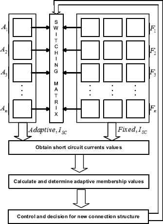
Block diagram for proposed approach
In the proposed approach, a different use of fuzzy technique is proposed. Typically, fuzzy logic that used in situations involving uncertainty, is used to determine the optimal panel layout in reconfiguration problem. The reason for using this technique in large-scale PV systems in the reconfiguration process is to identify the best-panel layout quickly. For this purpose, this radiation values based on the value of the short circuit currents are determined and according to fuzzy values determined by the proposed approach radiation values are grouped. These values grouped for adaptive and fixed arrays, matched appropriately and new optimal panel layout is obtained.
A. Obtaining short circuit currents: When a PV array is exposed to partial shading conditions, the output short circuit current value of each module will change, because the radiation values on the PV panels change. In the proposed method, our fuzzy partitioning based algorithm is taking the short circuit current values as input parameters. Both numbers of sub-modules in the adaptive panel and fixed panel (n) are obtained as short-circuit current values. The obtained values are sent to the next unit for calculating the fuzzy measurements.
B. Fuzzy measurement with adaptive values: The obtained connection structure that provides the maximum power from the system in the case of the partial shading of a PV system has an important role in the availability of the system. Therefore, this step in the reconfiguration approach can provide a higher amount of power. For this step, an efficiency and applicable fuzzy partitioning method solution is used for less complexity in the calculations20,21,22,23. The proposed system is a single-input single-output fuzzy structure. Therefore, input and output values are determined as a result of studies and observations. Radiation levels as a result of these observations are grouped into five different groups. These are, respectively, very low (VL), low (L), medium (M), high (H) and very high (VH) values. Especially, the most important advantage of the proposed approach, the optimal order on large-scale PV panels can be detected without any calculations. The method of the partitioning process, rather than being determined as constant, has been developed with a dynamic structure. For the different short-circuit current, the membership values may be illustrated as different structures. A flow chart of the method is shown in Fig. 6.

Fuzzy measurement with adaptive values
The amount of shading on a PV panel consists of radiation values in the range of 0–1000 W/m2. The value produced in response to this radiation is the amount of short-circuit current and is between 0–3.8A. However, because each sub-module in the fixed panel contained more than one PV panel, the obtained short circuit current values will be out of the expected value range. Therefore, the normalization of the values obtained from the fixed panel must be provided. The equation for the normalization process is given in Eq. (1). Some irradiance and short circuit current values obtained from the PV arrays are presented in Table 1.
| Adaptive Arrays | Fixed Arrays | |||||||
|---|---|---|---|---|---|---|---|---|
| No | Irradiance (W/m2) | ISC (A) | No | Irradiance (W/m2) | ISC (A) | ISC AVG | ||
| A1 | 300 | 1.138 | F1 | 750 | 850 | 900 | 9.486 | 3.162 |
| A2 | 300 | 1.138 | F2 | 650 | 750 | 500 | 7.209 | 2.403 |
| A3 | 300 | 1.138 | F3 | 600 | 1000 | 600 | 8.347 | 2.782 |
| A4 | 800 | 3.035 | F4 | 400 | 400 | 400 | 4.553 | 1.517 |
| A5 | 700 | 2.656 | F5 | 500 | 500 | 500 | 5.691 | 1.897 |
| A6 | 600 | 2.277 | F6 | 600 | 600 | 600 | 6.83 | 2.276 |
| A7 | 900 | 3.415 | F7 | 700 | 850 | 900 | 9.266 | 3.088 |
| A8 | 850 | 3.225 | F8 | 850 | 850 | 900 | 9.865 | 3.288 |
| A9 | 1000 | 3.794 | F9 | 850 | 900 | 1000 | 10.055 | 3.351 |
Irradiance and short circuit currents values
By using all of the short circuit current values (IscA and ISCavg), a minimum value and a maximum value have calculated. For this calculation, Eq. 2 and 3 are used. IscAi is the short circuit current from the adaptive panel. IscFi is the short circuit current from the fixed panel, ISCmin, is the minimum current value, ISCmax, is the maximum current value and n is a count of sub-modules.
The next step requires determining the range that the membership values frequently exist in. For this procedure, a control range and a threshold value are calculated by using Eq. 4 and 5. The lower limit is cntrlmin, while the upper limit is cntrlmax. The threshold value is threshold_value, and the count of expected membership value is the number_of_membership (NoM); and k is a constant and is determined experimentally.
When these values are considered, the range that the membership values are frequently in are calculated as illustrated in the pseudocode below. countmin, shows how many short circuit current values are in the range of cntrlmin. The value of countmax, shows how many short circuit current values are in range of cntrlmax.
| Step 1. Calculate Iscmin and Iscmax |
| Step 2. Calculate control ranges and threshold value |
| Step 3. If (countmin ≥ threshold_value) |
| start_value = Iscmin |
| Goto Step 4 |
| Else |
| Iscmin = the next minimum value |
| Goto Step 2 |
| Step 4. If (countmax ≥ threshold_value) |
| end_value = Iscmax |
| Else |
| Iscmax = the previous maximum value |
| Goto Step 2 |
| Step 5. Get start_value and end_value |
The start_value and end_value is the start point and end point, respectively, of the fuzzy measurements. This range is labeled with fuzzy labels by dividing the count of the membership values. When Table 1 is considered and constant, k, is 0.3, the membership values are obtained as shown in Fig. 7. Membership labels are very low (VL), low (L), medium (M), high (H) and very high (VH).
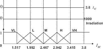
Relationship between fuzzy measurements and ISC
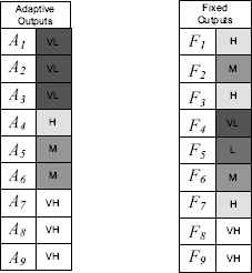
In Fig. 8, the membership values for each adaptive array are shown. The shades on this figure are illustrated as radiation values. When calculating the membership value of the fuzzy labels, we should determine the placement of the current value on the membership functions (e.g., 0.8L, 0.2M). The bigger value is the point value (0.8L); it will be the membership value to take for the current value. If both point values are the same, we would take the larger membership values. In Fig. 9, a membership value of 1.138A is illustrated.
One example of adaptive and fixed arrays
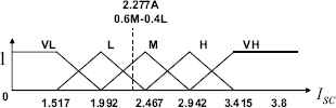
Membership of a short circuit current value
C. Control and Decision: The determined short circuit current values of the adaptive and fixed panels are sorted from very low (VL) to very high (VH). A crossing operation is applied to the sorting values as the minimum value of the fixed panel is mapped to the maximum value of the adaptive panel. For example, an adaptive array panel with a VL value can be matched with a panel with the VH values in the fixed array. A block diagram showing this condition is shown in Figure 10. In this way, the radiation values of the sub-modules in the system is averaged and the optimal result are determined. A connection structure that is calculated with that approach is shown in Fig. 10.
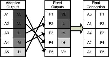
An example of the control and decision
3. Simulation and Experimental Results
In this study, simulations are actualized to overcome the disadvantages of the partial shading conditions on the PV arrays by testing the different sized arrays and different partial shading conditions. The characteristic attributes of the PV panels used in the simulations are given in Table 2. The input parameters used for the proposed algorithm are taken from the nine sub-modules. These radiation and current values are given in Table 1. The membership values of the state adaptive and fixed panels are illustrated in Table 3.
| Description | Value |
|---|---|
| Size of fixed arrays | 9×3 |
| Size of adaptive arrays | 9×1 |
| Minimum irradiance value of panels | 0 W/m2 |
| Maximum irradiance value of panels | 1000 W/m2 |
| Minimum ISC value of panels | 0 A |
| Maximum ISC value of panels | 3.8 A |
| Temperature | 25 °C |
| Maximum power (PMAX) of panels | 65 W |
Characteristics of PV Panel
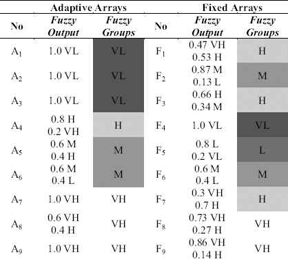
Membership Values
The columns titled fuzzy output in Table 3 are the points among the membership values measured as the fuzzy values. The column titled fuzzy group is determined by the membership value. The fuzzy group values are determined as discussed previously. This value is then sorted and applied to the cross process. The connection structure before the reconfiguration and the final structure are illustrated in Table 4. The relationship between the irradiance values on the PV panels are given in Table 5. When considering this relationship, the total irradiance value of the connected arrays are closer, as compared to before the reconfiguration. The radiance values changed from [933W/m2 - 1917W/m2] before the reconfiguration to [1117 W/m2 - 1533 W/m2] after the reconfiguration.
| Type of Array | Before Reconfiguration | ||||||||
| Adaptive | A1 | A2 | A3 | A4 | A5 | A6 | A7 | A8 | A9 |
| Fixed | F1 | F2 | F3 | F4 | F5 | F6 | F7 | F8 | F9 |
| Type of Array | After Reconfiguration | ||||||||
| Adaptive | A6 | A7 | A5 | A9 | A8 | A4 | A3 | A2 | A1 |
| Fixed | F1 | F2 | F3 | F4 | F5 | F6 | F7 | F8 | F9 |
The connection structure before and after reconfiguration
| Type of Array | Before Reconfiguration | ||||||||
| Adaptive Panel | A1 | A2 | A3 | A4 | A5 | A6 | A7 | A8 | A9 |
| Irradiance(A) (W/m2) | 300 | 300 | 300 | 800 | 700 | 600 | 900 | 850 | 1000 |
| Fixed Panel | F1 | F2 | F3 | F4 | F5 | F6 | F7 | F8 | F9 |
| Avg(Irradiance(F)) (W/m2) | 833 | 633 | 733 | 400 | 500 | 600 | 817 | 867 | 917 |
| sum_of_irradiance(W/m2) | 1133 | 933 | 1033 | 1200 | 1200 | 1200 | 1717 | 1717 | 1917 |
| After Reconfiguration | |||||||||
| Adaptive Panel | A6 | A7 | A5 | A9 | A8 | A4 | A3 | A2 | A1 |
| Irradiance(A) (W/m2) | 600 | 900 | 700 | 1000 | 850 | 800 | 300 | 300 | 300 |
| Fixed Panel | F1 | F2 | F3 | F4 | F5 | F6 | F7 | F8 | F9 |
| Avg(Irradiance(F)) (W/m2) | 833 | 633 | 733 | 400 | 500 | 600 | 817 | 867 | 917 |
| sum_of_irradiance(W/m2) | 1433 | 1533 | 1433 | 1400 | 1350 | 1400 | 1117 | 1167 | 1217 |
Irradiance and short circuit currents values
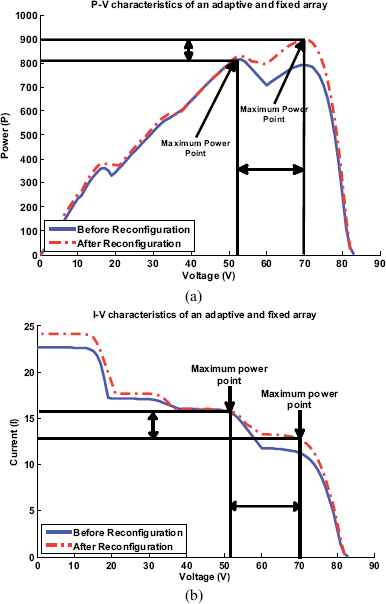
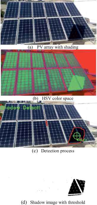
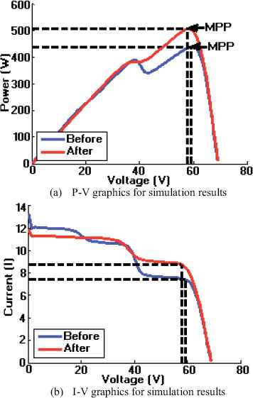
The two connection structures shown in Table 5 are actualized in the MATLAB environment. The obtained P-V and I-V graphics are given in Fig. 11 (a–b). As noticed in both of these figures, the proposed approach provides a larger power point than the conventional methods. However, the proposed approach does not contain any calculations to extend the process time. Hence, the system does not have the complexity and can actualize all operations in a minimum amount of time. The efficiency of the PV arrays will be at the maximum point. An experiment mechanism in 3×4 size is prepared for real-time testing of the proposed approach. A video is recorded by using this experimental setup and a camera. Then, the resulting full or partial shadings on the panels were determined by image processing algorithms implemented on the video image. An example scenario illustrating algorithm steps is presented in Fig. 12. In addition, the panel radiation values were obtained thanks to this algorithm and given to the fuzzy partitioning algorithm as input parameter. Finally, the results obtained from the proposed approach has been sent to the switching matrix. Thus it was determined the optimal panel layout. Connection layouts of before and after reconfiguration are given in Fig. 13-(a) and (b), respectively.
P-V and I-V graphics for reconfiguration process
Shadow detection for reconfiguration
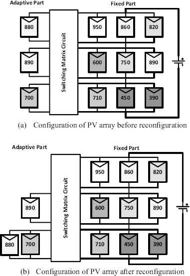
PV array configuration before and after the reconfiguration process
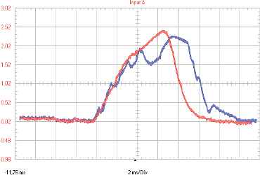
As can be seen from Fig. 13, the adaptive panel A1 and A3 are connected F3 and F1 is not connected to any adaptive panel. A2 is connected to the F2. The values of new connection layouts obtained by proposed fuzzy partitioning algorithm has measured by both MATLAB and oscilloscope in real-time. The results obtained in MATLAB for P-V and I-V changes, are also presented in Fig. 14-(a) and (b). Also, real-time measurement results obtained by the oscilloscope is shown in Fig. 15. According to measurements, the PV curve is provided a yield increase of approximately 15%. This change shows the results are given in Table 6.
P-V and I-V graphics
Experimental results for P-V graphics before and after reconfiguration scenario
| Description | Value |
|---|---|
| MPP value before reconfiguration (W) | 439,7053 |
| MPP value after reconfiguration (W) | 506,7223 |
| Power increasing (W) | 67,017 |
| Power increasing (%) | 15,2413 |
The amount of change for PV panels
Also, in this study, quitely efficient result are obtained in terms of the execution time. When the studies in the literature is analyzed, the selection of the optimal connection layout between possible connections of configurations obtained by switching matrix is taken more time. The comparison results of proposed approach and studies in the literature are presented in Table 7.
4. Conclusions
In this study, a fuzzy logic-based detection system for an optimal panel PV system is carried out. In the proposed approach, the short-circuit current value of the system through the current sensor was obtained. Afterwards, the current values were sent to the fuzzy calculation unit. In this unit, the short circuit currents are converted to radiation values and the panels are classified as parallel to the radiation values. The classified values, represents the shading degrees, are accelerated in the presence of optimal panel layouts with this classification process. The resulting output values are transmitted to the control decision unit. The final configuration is applied to the PV systems with the help of the switching matrix. This proposed approach provides energy efficiency on the PV curve of about 10%–15%.
The most important advantage of the fuzzy partitioning based reconfiguration approach is its ability to offer quick solutions for large PV systems. The classification of the panels, according to the short circuit current and radiation values, is the most important factor that allows the rapid detection. Another advantage of the proposed method is that it can operate independently of the type of connection.
Acknowledgement
This study has been supported by The Scientific and Technological Research Council of Turkey (TUBITAK 1001 Programme) under Research Project No: 112E214.
Footnotes
This study has been supported by the Scientific and Technological Research Council of Turkey (TUBITAK 1001 Programme) under Research Project No: 112E214
References
Cite this article
TY  - JOUR
AU  - Mehmet Karakose
AU  - Mehmet Baygin
AU  - Kagan Murat
AU  - Nursena Baygin
AU  - Erhan Akin
PY  - 2016
DA  - 2016/04/01
TI  - Fuzzy Based Reconfiguration Method Using Intelligent Partial Shadow Detection in PV Arrays*
JO  - International Journal of Computational Intelligence Systems
SP  - 202
EP  - 212
VL  - 9
IS  - 2
SN  - 1875-6883
UR  - https://doi.org/10.1080/18756891.2016.1150004
DO  - 10.1080/18756891.2016.1150004
ID  - Karakose2016
ER  -