
A Four-legged Robot’s Soft Feet Structural Design and Walking Gait Generated from Inverse Kinematics
- DOI
- 10.2991/jrnal.2018.5.3.4How to use a DOI?
- Keywords
- Soft material robot; robot’s foot sensing; statics balance condition
- Abstract
The conventional wheel is famous in the industrial mobile robot because it is simple to build and easy to control and to maneuver. On the other hand, the legged robot is complicated to control but has a high performance in locomotion like highly evolved legged-creatures. This research describes the four-legged robot design platform with the soft feet, which are made by silicone-material forming. The robot’s feet are implanted by the strain gauge sensor. The robot can percept the external force sensitively when its feet touch something. The research demonstrates the forward kinematics and inverse kinematics of a four-legged robot with three joints for each. The result has validated the kinematic equations by implementing them on the real dog-like pet robot. The robot walked with a pure walking gait and showed a sensing signal from the soft foot and ground contact.
- Copyright
- © 2018 The Authors. Published by Atlantis Press SARL.
- Open Access
- This is an open access article under the CC BY-NC license (http://creativecommons.org/licences/by-nc/4.0/).
1. INTRODUCTION
The legged robot consumes more energy than wheel type robot. The equation of motion of the legged robot is also complicated. However, the legged robot has good maneuverability and mobility similar to revolute vertebrate animals with legs. The robot can perform mimicking from animal’s movement using a mathematical model or a trained behavior. The smooth floor is a primary test that the robot can repeat its movement pattern when it walks with stable balance control condition. Moreover, the robot has to adapt its movement simultaneously on the stepping terrain or multi-levels. In the high-level cognition in fast movement, the human has the experiences to plan its motion before moving for example in a hurdle race. Elsewhere, the human can sometimes focus on the smartphone while he is walking without paying attention to everyday walking path. However, it is possible to make an accident. For those views basically, the robot has to be able to sense when the feet contact the ground in every direction. For the animal, the body is covered by skin which has a nerve cell to sense the impact force. The reviewed works use various methods regarding the sensors of the robot’s perception. The humanoid robot foot has an effective contact area of perception. Thus, the sensor is a flexible force sensor array with the spatial rectangle in Wu et al. [1]. The robot transfers weight to its foot while it is walking under a dynamic equilibrium criterion or zero moment point (ZMP). Next, a curvature sensor module can be embedded into the soft-bodied robots in Ozel et al. [2]. The sensor type is an electro-mechanical sensor that is fabricated and merged into a soft robot. For an application, a soft robotic grove has a soft fiber-reinforced actuator to sense the human hand movement as a human interface device in Polygerinos et al. [3]. Another sensor is a strain gauge, which is a skin-like, ultra-thin sensor. It can be bent and used for prosthetic devices in Sencadas et al. [4]. There is a research about soft robotic fingertips that is a similar idea to its use as a robot foot soft tip. The soft robotic fingertip has a metal bar as a bone, a body, and a skin layer. The receptors are strain gauges and PVDF films. The body is made of liquid silicone rubber in Hosoda et al. [5]. The soft robot is a series elastic actuator that interfaces with an environment. To control the soft robot is designed with impedance-controlled compliant actuators in Calanca and Fiorini [6]. For previous work of this research in Phunopas and Suwichien [7], the robot has a plastics material for robot foot. This paper presents to test the robot walking pattern with a defined static balanced condition and the sensing signals from the robot foot.
2. THE ROBOT STRUCTURES
The robot has four legs that have the same module for each leg. It has three joints for shoulder, wing and, knee. It has 12 joints. The robot size is approximately a small pet in 1 cubic-feet volume. The robot weight is about 2 kg including mini PC and battery. The robot body frame is made from ABS plastic as in Figure 1.
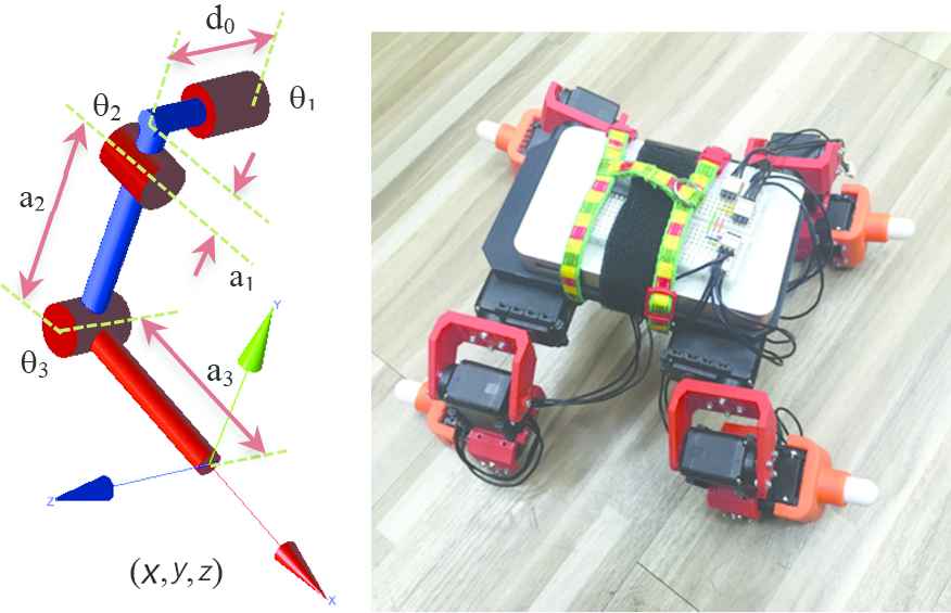
(Left) A robot leg configuration. (Right) The robot structure with four legs
2.1. Robot’s Soft Foot Design
The robot feet are made from soft material which is implanted a strain gauge sensor inside to sense the impact force as in Figure 2. From the sensor placement, it can sense on the vertical axial load because of its weight pressing and distribute in various directions along the axial load. However, it does not sense the torsional and bending load. A strain gauge sensor has an amplifier circuit which sends the analog signal to the analog to digital converter.
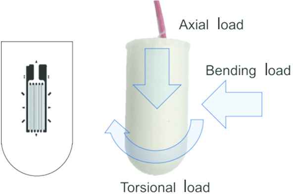
The robot foot material is the end-effector of the robot leg or the soft tip
3. KINEMATICS
The summary of forward and inverse kinematics is used to control the robot posture. The equation is individually applied to each leg. First is the forward kinematics in Eqs. (1–3):
Second is inverse kinematics in Eqs. (4–6) that is the solved equations from Eqs. (1–3) using the Harmonic Addition Theorem. The singularity condition is that θ2 equals to 0° in case of dividing by zero in Eq. (6).
The sequence of the robot walking gait and static balance configuration is generated in the walking gait pattern.
4. WALKING GAIT PATTERN
The walking gait possibly has many patterns under the condition of a smooth floor with the ZMP area as a stability criterion. Commonly, ZMP is used for dynamical walking, but in this case, it is to initiate some conditions to make the robot walk continuously with no falling head over heels or stumbling as in Figure 3. The robot configurations are posed by kinematic equations to keep all feet’s tip or the end-effector of the robot’s legs on the same planar floor. The center of gravity is approximately in the ZMP area on the floor plane. The robot’s body plane orientates itself around the XYZ axes, as shown in Figure 4.
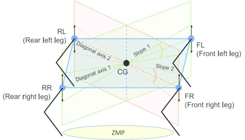
The robot’s body plane can change its planar slope when changing each leg’s height on the smooth floor

The defined normal vector of the robot’s body plane has three orientations: roll, pitch, and yaw
The normal vector is created to define the robot’s body plane in Eqs. (11–12). In Eq. (13), there are three rotations, roll, pitch, and yaw, for the X, Y, and Z axes respectively.
The normal vector is perpendicular to the robot’s body plane. The point of the normal vector represents the tilt plane and the transfer CG position. The robot walks by lifting its legs one-by-one. Therefore, when the other three legs are on the floor, the CG will transfer the ZMP area to the floor area contacted by the three feet. The normal vector will move along the diagonal axis 1 from point P2 to P4 and along diagonal axis 2 from point P1 to P3, as shown in Figure 5.
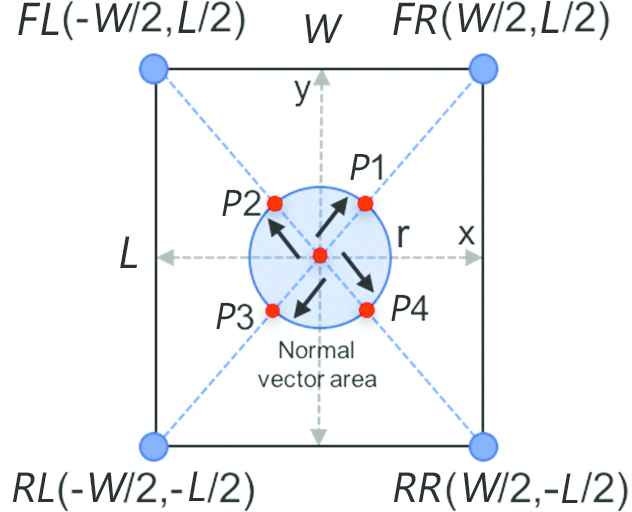
From the top view, the point of the normal vector moves in the unit circle of the normal vector area
4.1. Control System
The robot has a strain gauge sensor inside each foot, which has the job of detecting the floor contact. The control system integrates the information on the angle of every joint and the end-effector positions. It can compute the robot configurations under the ZMP method when the robot’s feet contact the floor. Respectively to the walking-gait pattern, the robot walks in a sequence, sensing the floor contact simultaneously. Figure 6 shows the hardware and the software that support the robot system. The computer sends a command to the robot by writing the motor’s trajectory. The strain gauge sensor amplifier is the differential bridge operational amplifier circuit with gain adjustment. The output analog voltage is 0–3.5 V, which is compatible to the analog input of the general microcontroller.
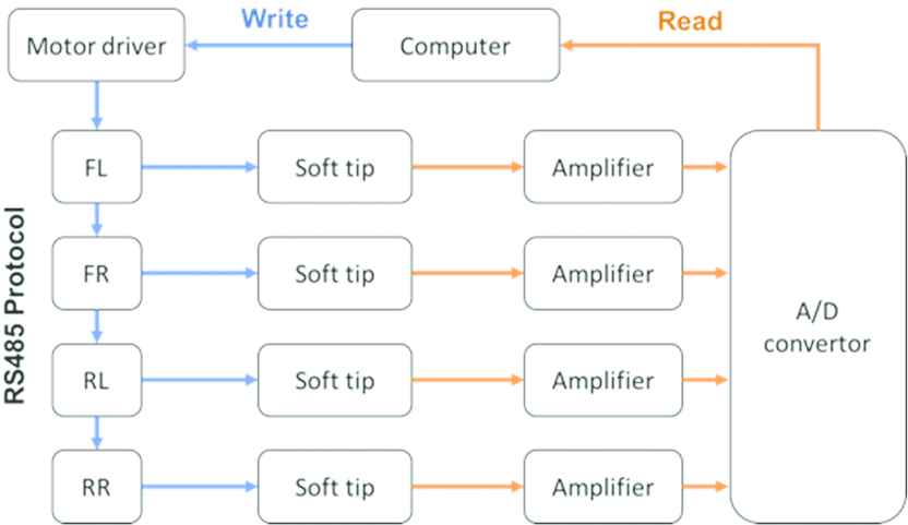
The soft tip foot of each leg can sense the floor contact signal. Moreover, the computer reads the signals of the floor-contact detection
5. RESULT
The first experiment showed the signal from a robot foot in Figure 7 when it contacted the floor in the axial load. Similarly, the four legs have the same result because it has the same structure.
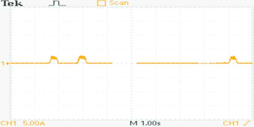
A soft robot foot contacted the floor. The analog voltage signal is measured by oscilloscope
In the second experiment, the robot walks applying the designed walking gait. The walking gait is generated from kinematic equations. For every walking step, one leg paces and the remaining three legs are on the floor, as in Tables 1 and 2.
| t | Front left leg | Rear right leg | Front right leg | Rear left leg | ||||||||
|---|---|---|---|---|---|---|---|---|---|---|---|---|
| θ1 | θ2 | θ3 | θ1 | θ2 | θ3 | θ1 | θ2 | θ3 | θ1 | θ2 | θ3 | |
| 0 | 20 | −5 | 55 | −20 | −5 | −55 | −20 | 5 | −55 | 20 | 5 | 55 |
| 1 | 20 | −5 | 55 | −19 | −5 | −64 | −20 | 5 | −55 | 20 | 5 | 55 |
| 2 | 18 | −5 | 70 | −19 | −5 | −64 | −20 | 5 | −55 | 20 | 5 | 55 |
| 3 | 18 | −6 | 79 | −20 | −5 | −55 | −20 | 5 | −55 | 20 | 5 | 55 |
One pace of the front left leg and the relative joint angles (°) of all legs
| t | Front left leg | Rear right leg | Front right leg | Rear left leg | ||||
|---|---|---|---|---|---|---|---|---|
| x | z | x | z | x | z | x | z | |
| 0 | −103.57 | −103.07 | −103.57 | −103.07 | −103.57 | −103.07 | −103.57 | −103.07 |
| 1 | −103.57 | −103.07 | −103.57 | −93.07 | −103.57 | −103.07 | −103.57 | −103.07 |
| 2 | −87.86 | −102.65 | −103.57 | −93.07 | −103.57 | −103.07 | −103.57 | −103.07 |
| 3 | −76.01 | −103.07 | −103.57 | −103.07 | −103.57 | −103.07 | −103.57 | −103.07 |
One pace of the front left leg and the relative foot tip XZ-positions (mm) of all legs
6. DISCUSSION
The soft material is made of silicone. A hardness level is a maximum number, but it is still too soft to take the robot weight. Consequently, the soft robot foot is immoderately deformed its shape. The strain gauge sensor is very fragile and easy to be broken. Due to the robot moves dynamically, CG, inertia and external force affect the system. The walking stability constraint is very complicated to maintain its balance when the robot walks.
7. CONCLUSION
The robot can walk and sense the floor contact from the soft foot using the implanted strain gauge sensor. The foot tip position and trajectory can independently be designed depending on the solved kinematic equations coherently. However, the walking gait in the fixed pattern is very difficult to define the stability state. It had better apply the control law or soft computation for robot control.
ACKNOWLEDGMENT
King Mongkut’s University of Technology North Bangkok and Kyushu Institute of Technology have supported this research.
Authors Introduction
Dr. Amornphun Phunopas
 He graduated Doctor course at Department of Mechanical Information Science and Technology in Kyushu Institute of Technology. He is a lecturer in the Department of Production Engineering at King Mongkut’s University of Technology North Bangkok.
Dr. Eiji Hayashi
 He graduated Doctor course at Division of Science and Engineering in Waseda University. He is a Professor in the Faculty of Computer Science and Systems Engineering in Kyushu Institute of Technology.
REFERENCES
Cite this article
TY  - JOUR
AU  - Amornphun Phunopas
AU  - Eiji Hayashi
PY  - 2018
DA  - 2018/12/01
TI  - A Four-legged Robot’s Soft Feet Structural Design and Walking Gait Generated from Inverse Kinematics
JO  - Journal of Robotics, Networking and Artificial Life
SP  - 161
EP  - 164
VL  - 5
IS  - 3
SN  - 2352-6386
UR  - https://doi.org/10.2991/jrnal.2018.5.3.4
DO  - 10.2991/jrnal.2018.5.3.4
ID  - Phunopas2018
ER  -