
Multi-Motor Synchronous Control with CANopen
- DOI
- 10.2991/jrnal.k.190220.006How to use a DOI?
- Keywords
- CAN bus; CANopen; brushless DC motors
- Abstract
A Brushless DC (BLDC) motors synchronous control system based on the CANopen (a communication protocol and device profile specification for automatic embedded systems) protocol is proposed in this paper. Multi-motor control is popular in robot or automation system, and the synchronization is an important issue, may be the key issue. The CANopen is a solution, due to Process Data Object (PDO) protocol. A Texas Instruments microcontroller TMS320F28069 is used as master to control six BLDC motors used as slave in this paper. The Master sends synchronization object to slaves’ base on the communication profile CAN (Controller Area Network) in Automation (CiA) 301 and the motion control profile CiA402. The system suns at 500 kbits/s and 1 Mbits/s transmission rate by setting PDO. The firmware details in this paper to show six-motor synchronous control.
- Copyright
- © 2019 The Authors. Published by Atlantis Press SARL.
- Open Access
- This is an open access article distributed under the CC BY-NC 4.0 license (http://creativecommons.org/licenses/by-nc/4.0/).
1. INTRODUCTION
Multi-motor synchronized control is an important and key issue in robot or automation system. How a communication protocol supports synchronization is discussed in many literatures [1]. As mentioned CAN communication for complex in-vehicle networks can reduce the cost of hardware configuration and maintenance [2] is similar to [1], but the CANopen protocol is adopted and supports compatibility. The master communicate with the devices from different manufacturers. CAN is also widely used in the industrial field due to the better error mechanism and high transmission rate [3]. The CANopen protocol also defines device specifications for industrial devices. This paper will refer to the Network Management (NMT) object, which CANopen basic communication specification is mentioned in Fan et al. [4] and Huang [5]. The service data object (SDO) is used to ask or set parameter for any single node. And the Process Data Object (PDO) is the object communication code for instant communication and the SYNC synchronization command. The target of the paper is the synchronous control of six Brushless DC (BLDC) motors, through the basic communication specification CiA 301 [6] and the motion device specification CiA 402 [7]. The CAN peripheral of TI TMS320F28069, master, is used to handle the CAN communication, and the CANOpen protocol is performed by program. The parameters of target speed, acceleration and deceleration on the Maxon EPOS4 motor drive could be set and synchronous controlled. The speed mode of the CiA 402 is used to achieve position control of the motor. The updating rate for six motors synchronous control will be discussed in this paper.
2. SYSTEM ARCHITECTURE
The system architecture is shown in Figure 1. The system includes a mater (TI’s TMS320F28069), CAN driver (Renesas’ R2A25416SP) and motor drivers (Maxon’s EPOS4) with motors.
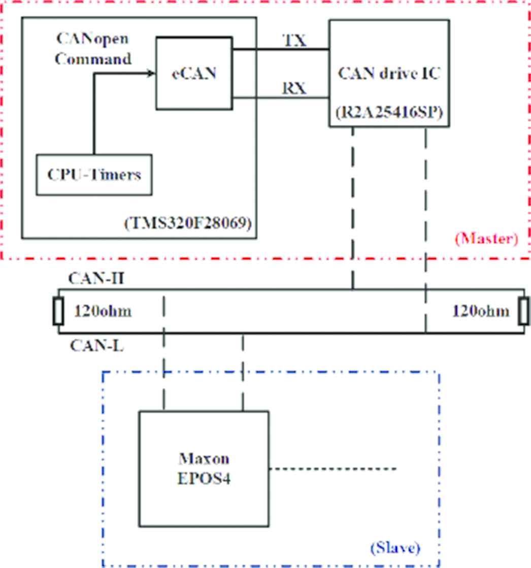
System architecture diagram.
2.1. Master - TI TMS320F28069
The build-in peripherals of TMS320F28069, CAN module and timer, are used in the CAN master. Due to digital format of CAN module signal, a driver is necessary to convert signal to differential signals of CAN-H and CAN-L. These two wires are connected directly to CAN bus. The timer is sued to trigger CPU to set the new target speed, acceleration and deceleration values of the slaves every fixed time interval.
2.2. Slave - Maxon EPOS4 Drive
The Maxon EPOS4 is adopted in system to drive motor, the CAN communication interface is built in, and the CiA 301 and 402 object specifications are supported by this driver. In this paper, it is selected as the slaves to receive the target speed, acceleration or deceleration from the master for motor control.
2.3. CAN Transport Packets
The CAN2.0A format is shown in Figure 2, what is used in CANopen protocol. This format is also used in this paper, it is the key of calculate communication capability, later. However, the format includes stuffing bit, and this bit stuffing mechanism is used to detect short even. The maximum of stuffing bits generated by the bit stuffing mechanism is discussed in Zeltwanger [8], as shown in Equation (1). The first 4 bits of the 11 bits identifier (ID) of the arbitration field in a single complete packet are defined as the control code, and the else 7 bits specified in the following are the node ID. These 11 bits are collectively referred to as the communication object identifier, and is followed by corresponding format specifications for the data sections in the packet.
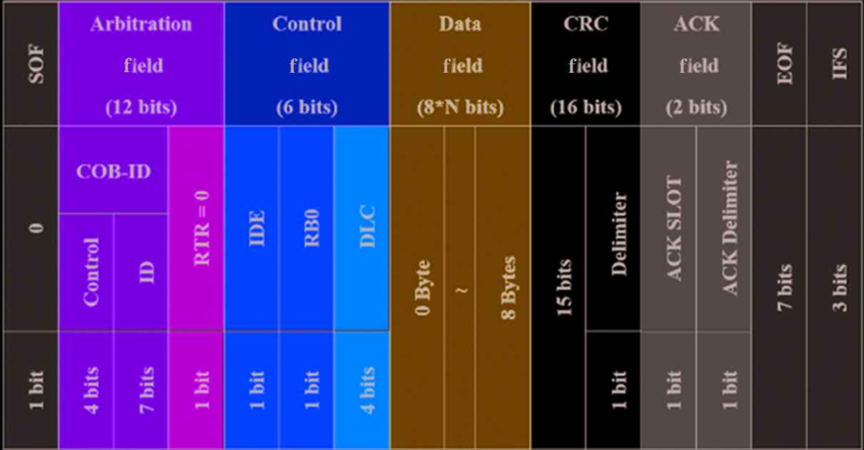
Base of CAN data frame format.
3. SOFTWARE ARCHITECTURE
In the CANopen CiA 301 protocol, a master must arrange communication relationships between a transmit- and a receive-PDO with SDO. CANopen Application layer and communication profile [6] is stipulated that the NMT must be used to control the working state of the device before using the SDO or PDO. Each device has a working state machine. The master controls the working state of the node through the NMT. As shown in Table 1, if people like to use SDO, the node working state have be set into the pre-operation mode. If PDO, the node in operation mode is necessary.
| Pre-operational | Operational | Stopped | |
|---|---|---|---|
| NMT | √ | √ | √ |
| PDO | √ | ||
| SDO | √ | √ | |
| SYNC | √ | √ |
States and communication objects [6]
In the master, the timer is used to trigger master to update the parameters of the PDO mapping to the device periodically. These parameters are the motion device state machine control object, such as the target speed object, the acceleration object, and the deceleration object. The data type of each object is also shown in Table 2.
| Object | Data type |
|---|---|
| 6040h: Control word | UNSIGNED 16 (2 Bytes) |
| 60FFh: Target velocity | INTEGER 32 (4 Bytes) |
| 6083h: Acceleration | UNSIGNED 32 (4 Bytes) |
| 6084h: Profile deceleration | UNSIGNED 32 (4 Bytes) |
Data format of the object [7]
3.1. Implementation Process Data Object
In this paper, PDO is used for parameter setting and synchronous control. The NMT object communication code is used to set the working state of the node, and the NMT object includes the single or broadcast mode. Due to multiple nodes in the proposed system, the working state of all nodes is set to the operation mode in the broadcast mode. When the working state of node is the pre-operation mode, the node could process the SDO object. It is necessary for the PDO usage, the PDO mapping function of the node must be set by SDO in advance. The SDO is only use in a point-to-point scheme. A node has to respond the SDO send from the master in 1 ms, as shown in Figure 3a.
After completing the PDO setting, the working mode of a node needs to be set to the working mode, and then the PDO function is valid. Note, it is important, when the nodes receive the PDO from the master, the nodes will wait for the SYNC command from the master to start to achieve the command. Here, this SYNC is a broadcast signal without data, and all of the motors can start simultaneously, as shown in Figure 3b.
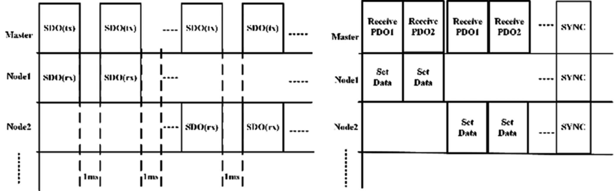
Sequence in time.
3.2. Compare SDO with PDO for Synchronized Control
Figure 4 shows the comparison of SDO and PDO for synchronized control with three parameters, which lengths are 1, 2 and 4 bytes. Because the SDO has a specific format in the data field when setting the object parameter to a node. Three packets are necessary, due to setting three object parameters in SDO mode. After setting, the node will return 4 bytes of response to the master. However, after PDO mapping function is performed in SDO mode, only 8 bytes of one packet is required to set object parameters.
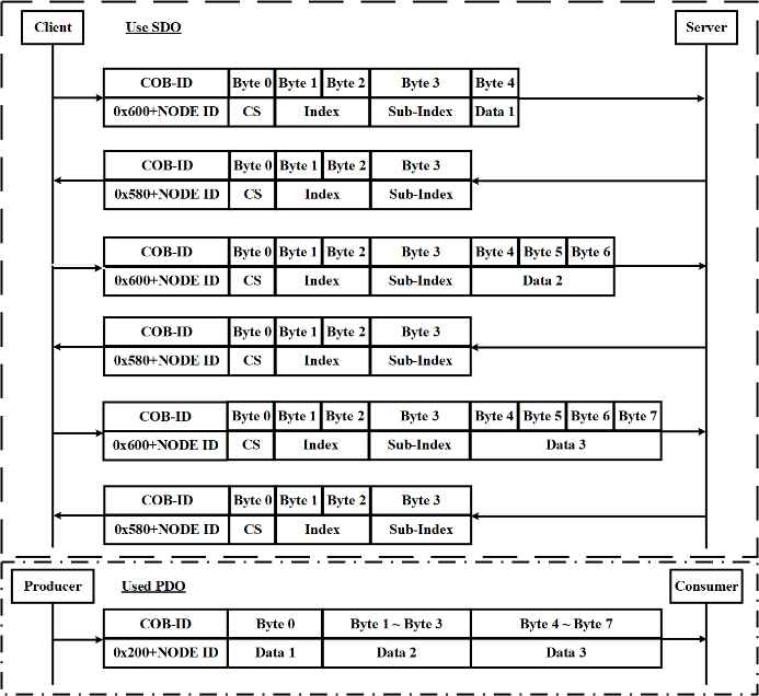
SDO vs PDO [5].
4. EXPERIMENTAL RESULTS
Figure 5 presents the system diagram of the experiment. As mentioned above, the master, TI TMS320F28069, and CAN driver in red dash box. The blue dash box shows the salve, and every slave includes a Maxon drive and a BLDC motor. Obviously, the CAN bus is used to link master and all slaves in parallel.
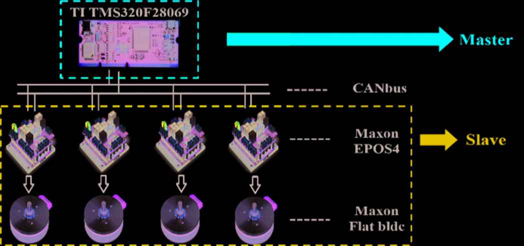
Experiment system.
4.1. Method of Updating Speed Commands
The system minimize requirement is that every slave is updated the driver commands every 0.1 s for synchronized control. These commands are the target speed, acceleration, deceleration and control word, and these four parameters are arranged into two groups of PDO, means two PDO mapping. When the all slaves (named consumer in PDO mode) received all PDO parameters from the master (named producer in PDO mode), and then the master sends a broadcast SYNC signal to trigger all slaves.
4.2. Node Capacity Calculation
To make sure how many slaves could be control synchronously in the proposed system, the node capacity calculation is necessary. As discussed previously, CANopen follows the packet format of CAN2.0A, which is present in Figure 1. The length of the minimum packet which never includes any data byte is 47 bits, which includes the inter-frame space field already. The length of a packet depends on the object. The packet’s length without stuff bit can be calculated from Equation (2). Moreover, in the actual situation, the stuff bit must be considered, and its length could get from Equation (3).
In SDO mode, the maximum number of nodes controlled synchronously in 0.1 s is derived as Equation (4). Note, the 8 ms is the extra inter-frame space requested by Maxon for 8 packets. First, the SDO_Packet_Length equals to the length of 4 parameter SDO packets plus 4 response packets. Note, the parameter SDO packet includes the minimums length (55 bits), 4 bytes (CS, index, and sub-index) and data bytes as shown in Table 2, and the exact bit number can get from Equation (3). Moreover, the response packet is fixed to 4 bytes plus 55 bits. Finally, the SDO packet is equal to 900 bits. And node number can be get from Equation (4).
On the other hand, the PDO calculation is shown in Equation (5). Here, the one SYNC packet (55 bits) is necessary for every node in 0.1 s. Next, PDO_Packet_Length includes two PDO packets, and the data lengths of the first and second PDO pocket are 8 and 6 bytes, respectively. In short, PDO_Packet_Length is equal to 250 bits.
The calculation results are present in Table 3 for the different communication mode and different baud rates. However, the maximum number of nodes is 127 in CANopen, it means that the rate of command updation could be increased in this case.
| SDO | PDO | |
|---|---|---|
| 500 kbits/s | 10 | 199 (127 in CANopen) |
| 1 Mbits/s | 11 | 399 (127 in CANopen) |
Maximum number of nodes
4.3. Experimental Results of Position Control
The experimental results of position control shown in Figure 6a and 6b is the initial/finish status. This experiment run in the PDO mode. From left to right, the first and third motors are controlled in the same commands, and the second and fourth are in the other same commands. They are synchronous stopped at the same two positions. The results show the proposed CANopen synchronous control is workable.
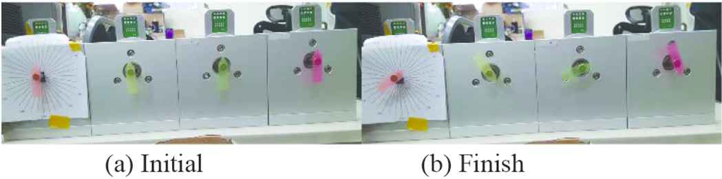
Position experiments.
5. CONCLUSION
This paper proposes a multi-node synchronization control system. The system includes the CiA 301 and the CiA 402 of the CANopen protocol and use the PDO and SYNC object for synchronization control. The protocol is detailed and the capacity is calculated in the paper. Finally, the experimental results shown the proposed system work well.
ACKNOWLEDGMENTS
This work is partially supported by the Naroller (Taiwan) Ltd. and also by the Ministry of Science and Technology, Taiwan, ROC, under contract No. MOST 107-2221-E-224-054 and 106-2218-E-150-001.
Authors Introduction
Asst. Prof. Chung-Wen Hung
 Dr. Hung got his PhD from National Taiwan University, Taiwan, ROC. Currently, he is an Asst. Prof. in the Department of Electrical Engineering, National Yunlin University of Science and Technology. His research interest focus on IoT, IIoT, MCU application and motor control.
Mr. Roger CL Lee
 Roger Cheng-Lung Lee received the B.S. and M.S. degree from the University of Southern California, Los Angeles, CA, USA, in 1999 and 2000, respectively, both in electrical engineering. He is currently working toward the PhD degree in the Department of Mechanical Engineering at the National Taiwan University, Taipei, Taiwan. His research interests focus on high speed motors and the relevant drivers.
Mr. Shih-Ting Yu
 He received the B.S. degree in electrical engineering from National Chin-Yi University of Technology, Taichung, Taiwan in 2017. He is currently doing Master of Electrical Engineering at National Yunlin University of Science and Technology, Yunlin, Taiwan, ROC. His research interest is motor control.
Mr. Bo-Kai Huang
 He received the B.S. and M.S. degrees in electrical engineering from National Yunlin University of Science and Technology, Yunlin, Taiwan, ROC. Since 2017, he has been a R&D engineer in the Chroma Electronics Co., Ltd., R.O.C., and his research interest is motor control.
REFERENCES
Cite this article
TY  - JOUR
AU  - Chung-Wen Hung
AU  - Roger CL Lee
AU  - Bo-Kai Huang
AU  - Shih-Ting Yu
PY  - 2019
DA  - 2019/03/30
TI  - Multi-Motor Synchronous Control with CANopen
JO  - Journal of Robotics, Networking and Artificial Life
SP  - 236
EP  - 240
VL  - 5
IS  - 4
SN  - 2352-6386
UR  - https://doi.org/10.2991/jrnal.k.190220.006
DO  - 10.2991/jrnal.k.190220.006
ID  - Hung2019
ER  -