
Tumble Avoidance System for Rescue Robot by Estimating the Contact Points using a 3D Depth Sensor
- DOI
- 10.2991/jrnal.k.190828.008How to use a DOI?
- Keywords
- Rescue robot; tumble avoidance; normalized energy stability margin; 3D depth sensor
- Abstract
Rescue robots are expected to perform works in hazardous areas. However, when the robot runs on a rough terrain, fatal rollover falling sometimes occurs. Therefore, we propose a tumble-risk-assessment system, which calculates a normalized energy stability margin by using a 3D depth sensor. Moreover, a control system to avoid the tumble situation by moving the sub-crawlers automatically is proposed. We implemented the proposed systems to a real robot, carried out experiments, and confirmed the effectiveness of the proposed method.
- Copyright
- © 2019 The Authors. Published by Atlantis Press SARL.
- Open Access
- This is an open access article distributed under the CC BY-NC 4.0 license (http://creativecommons.org/licenses/by-nc/4.0/).
1. INTRODUCTION
Recently, times of emergency have necessitated rapid searches for victims in collapsed buildings. However, searches conducted by humans involve risks of secondary disasters. Therefore, it is expected that rescue robots search for victims before entry by humans [1].
Most existing rescue robots are controlled by teleoperation, because fully autonomous control may be dangerous in uncertain disaster environments. However, full teleoperation is difficult for a human operator, because a rescue robot has multiple degrees of freedom in general. Therefore, human support control system, “semi-autonomous control” in other words, is needed [2].
One of most critical incidents is falling down of the robot. Figure 1 shows a robot which falls down in the RoboCup Rescue Robot League competition. As shown in Figure 1, the fallen robot cannot run again without someone’s supports.
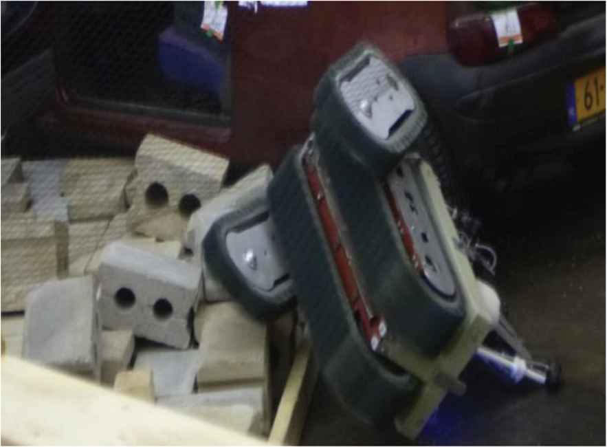
Fallen robot in RoboCup rescue competition.
Okada et al. [3] proposed a semi-autonomous control system to avoid the falling-down situation by using the normalized energy stability margin (SNE) proposed by Hirose et al. [4]. However, the authors assume that the circumference of the robot contacts with the ground. Therefore, the system often cannot calculate the risk of the fall precisely, when the robot runs on a rough terrain, because the contact point between the robot and the ground may locate on the inner part of the robot.
In the existing works, the assumption about the contact points between the ground and the robot are necessary because SNE is obtained from the position of the contact points and it is difficult to get the precise position of the contact point. However, the assumptions of existing studied do not often satisfy when the robot runs on a rough terrain.
In our previous work, we developed estimating system of the contact points by using a reconstructed 3D map from the point cloud data of a 3D depth sensor, such as KINECT [5]. Therefore, the purpose of this study is to develop a semi-autonomous system to avoid the falling-down situation. In our system, we use partial differentiation of the SNE. The contact points are estimated by the system which is developed in our previous work.
2. CALCULATION METHOD OF NORMALIZED ENERGY STABILITY MARGIN
2.1. Normalized Energy Stability Margin
The normalized energy stability margin proposed by Hirose et al. [4] is one of the most popular indexes of risk of fall because the calculation is very simple. The normalized energy stability margin SNE is obtained by Equation (1)
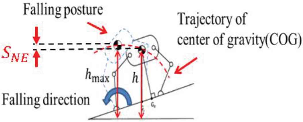
Normalized energy stability margin.
2.2. Estimation of Contact Points
To estimate the contact points between the ground and the robot, the 3D map is reconstructed by using a 3D depth sensor. The simultaneous localization and mapping technique is used for the map building with Robot Operation System (ROS) by Willow Garage. By using ROS, a developer can easily use someone’s open-source programs. In this study, we use Real-Time Appearance-Based Mapping (RTAB-Map) developed by Labbe et al. [6]. And since we also use ROS, other developers can easily use our system, only putting a 3D depth sensor on the robot.
2.3. Estimation of Axis of Fall
We set the detection area along with the shape of the bottom part of the robot as shown in Figure 3. If a point in the 3D map exists in the detection area, the point is set as a contact point as shown in Figure 4. A convex polygon is made from the contact points and the edges of the convex polygon are set as the axes of fall. After obtaining the axes of fall, the normalized energy stability margin SNE is calculated by Equation (1).
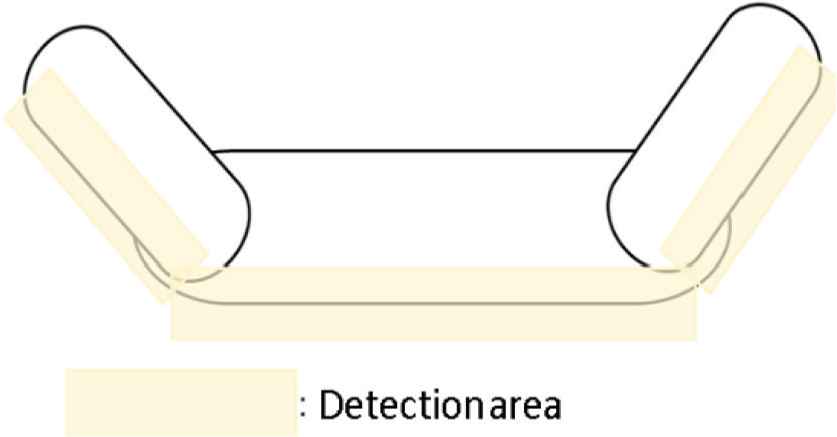
Detection area for contact points.
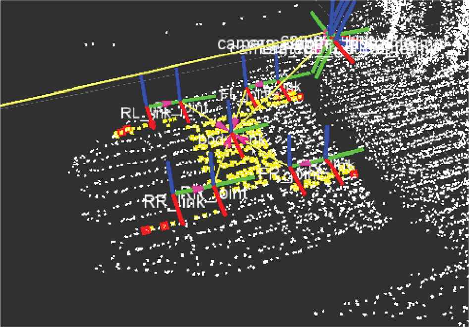
Estimation result of contact points and axes of fall (White points are environment points of 3D map, yellow points are contact points between ground and robot, and red points are points which configure axes of fall.).
3. CONTROL METHOD OF SUB-CRAWLERS
To avoid the tumble situation, SNE should be increased by moving the sub-crawlers, when the SNE becomes almost zero. Therefore, the sub-crawlers should be moved so that
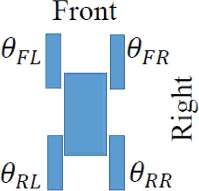
Definition of θYX = θFR, θFL, θRR, θRL (Top view).
In the proposed control system, the robot is teleoperated by an operator. However, when the SNE becomes almost zero, the target angles of the sub-crawlers are used as Equation (4) instead of the input by the operator to avoid the tumble situation. Figure 6 shows the control flow chart of the proposed control system.
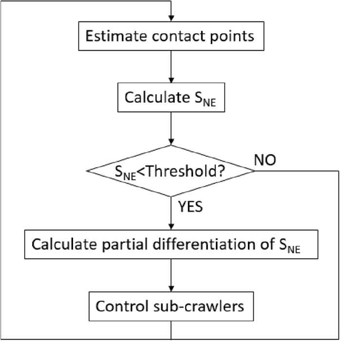
Flow chart of the proposed control system.
4. EXPERIMENT
4.1. Experiment Method
The purpose of the experiment is to verify the effectiveness of the proposed method compared with the existing method [3]. The experiment environment and the motion of the robot is shown in Figure 7. The left side of the robot is on the concrete block and the other side is on the ground. The robot repeats stop and go for 2.5 s. The evaluation index is SNE.
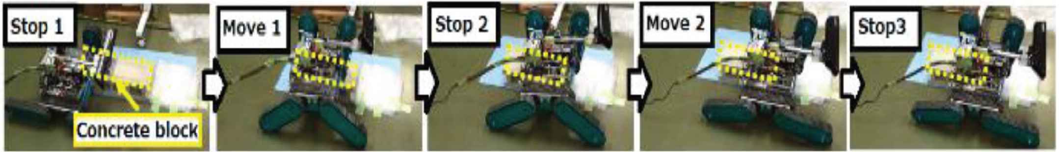
The experiment environment and the motion of the robot (proposed method).
4.2. Result
The result of the experiment is shown in Figure 8. The horizontal axis is time and the vertical axis is SNE. The green and orange line shows the SNE by the existing method and the proposed method, respectively. As shown in Figure 8, in the case of the proposed method, the decrease of the SNE becomes gradual after 9.2 s and the SNE increases after 10 s. On the other hand, in the case of the existing method, the SNE continues to decrease after 9.2 s. Note that the reason, why the SNE was slightly changed at 6.6 s and around 10.5 s when the robot stops, is that the position of the robot estimated by RTAB-Map was slightly changed (about 6 cm).
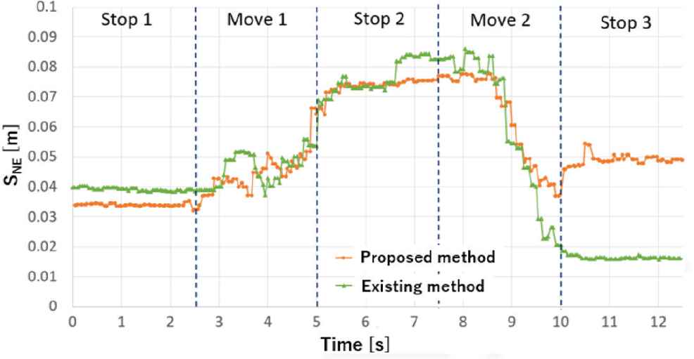
The result of the experiment.
4.3. Consideration
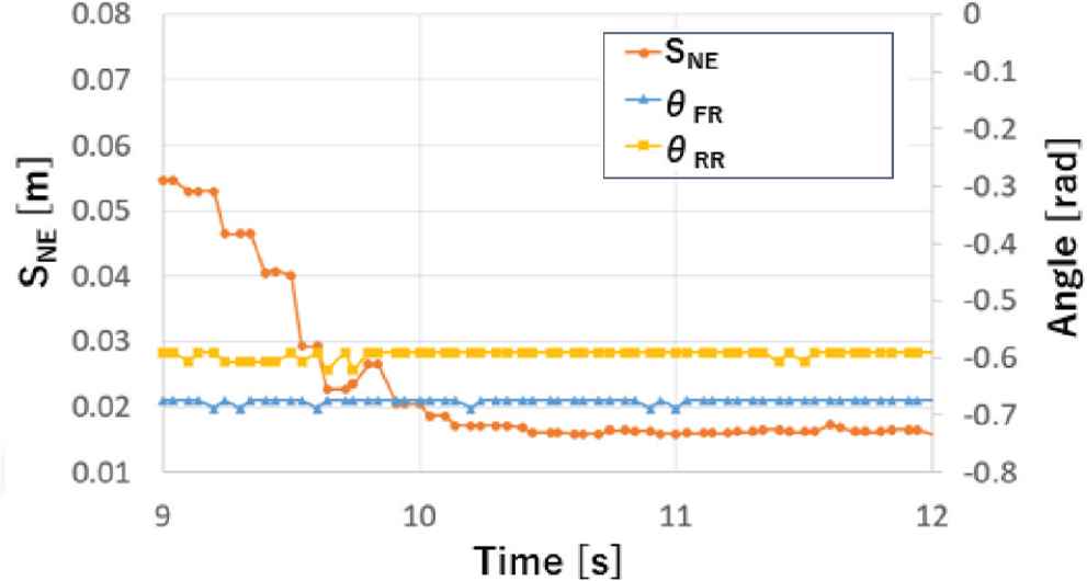
As shown in Figure 8, the large difference between the proposed method and the existing method is observed after 9 s. Therefore, Figures 9 and 10 show the angle of the sub-crawlers after 9 s in the case of the existing method and the proposed method, respectively.
Angle of the sub-crawlers (existing method).

Angle of the sub-crawlers (proposed method).
As shown in Figure 9, the sub-crawlers did not move because of the assumption that the circumference of the robot contacts with the block and the ground. On the other hand, as shown in Figure 10, in the case of the proposed method, the front- and rear-right sub-crawlers are moved after 9.2 s, and then the SNE increases, because the contact points and the axis of the fall are precisely estimated and the motions of the sub-crawlers are correct. The average of SNE from 11 to 12 s of the proposed method and the existing method are about 0.049 and 0.016 m, respectively.
5. CONCLUSION
In this study, we propose a tumble-risk-assessment system, which calculates a normalized energy stability margin by using a 3D depth sensor. Moreover, a control system to avoid the tumble situation by moving the sub-crawlers automatically is proposed. We implemented the proposed systems to a real robot, carried out experiments, and confirmed the effectiveness of the proposed method.
In the situation where it is difficult for the existing to control the proposed method can increase SNE by about three times.
The future works are to carry out the experiment on rough terrains and to develop a system not to become a dangerous situation by predicting the SNE.
CONFLICTS OF INTEREST
The authors declare they have no conflicts of interest.
Authors Introduction
Dr. Noritaka Sato
 He received Doctor of Engineering degree from The University of Electro-Communications in 2009. He was a Program-Specific Assistant Professor of Kyoto University in 2009–2011 and is an Assistant Professor of Nagoya Institute of Technology since 2011. His research interests include human robot interaction for rescue robots, rehabilitation-assist robots and industrial robots. He is a member of the IEEE, RSJ and SICE.
Mr. Kotaro Ohshima
 He received Master of Engineering degree from Nagoya Institute of Technology in 2016. His research interests include control system, system integration and teleoperation system for rescue robots.
Prof. Yoshifumi Morita
 He is a Professor in the Department of Electrical and Mechanical Engineering at Nagoya Institute of Technology. He received the PhD degree from Nagoya Institute of Technology in 1998. His current research interests are rehabilitation support robot/device and robot teaching.
REFERENCES
Cite this article
TY  - JOUR
AU  - Noritaka Sato
AU  - Kotaro Ohshima
AU  - Yoshifumi Morita
PY  - 2019
DA  - 2019/09/10
TI  - Tumble Avoidance System for Rescue Robot by Estimating the Contact Points using a 3D Depth Sensor
JO  - Journal of Robotics, Networking and Artificial Life
SP  - 109
EP  - 112
VL  - 6
IS  - 2
SN  - 2352-6386
UR  - https://doi.org/10.2991/jrnal.k.190828.008
DO  - 10.2991/jrnal.k.190828.008
ID  - Sato2019
ER  -