
Design of a PID Controller using a Fictitious Exogenous Signal for a Fluctuation System
- DOI
- 10.2991/jrnal.k.190828.010How to use a DOI?
- Keywords
- PID control; Fictitious Exogenous Signal; fictitious reference iterative tuning
- Abstract
The fictitious reference iterative tuning method is used to design Proportional–Integral–Derivative (PID) controllers to achieve desired performance for industrial machines. However, the desired control performance cannot be obtained by this method, if the system characteristics changed in steady state. In this paper, design method of a PID controller using the Fictitious Exogenous Signal is proposed. The change of system characteristics is considered as an impulse-like virtual disturbance. The Fictitious Exogenous Signal to calculate PID parameters is obtained from a set of operational data. The effectiveness of the proposed method has been verified by numerical examples.
- Copyright
- © 2019 The Authors. Published by Atlantis Press SARL.
- Open Access
- This is an open access article distributed under the CC BY-NC 4.0 license (http://creativecommons.org/licenses/by-nc/4.0/).
1. INTRODUCTION
PID controllers has been used in a lot of industrial machines. Appropriate PID parameters are necessary for a desired performance. However, the parameters are difficult to be decided by trial and error. Therefore, the Chien–Hrones–Reswick (CHR) method, a conventional method, is widely used. In this method, the proportional gain, the integral gain and the differential gain are determined based on the parameters of the controlled system, respectively. However, this method can be applied only when the system parameters are known, and desired response characteristics cannot necessarily be obtained in some cases.
Recently, the Fictitious Reference Iterative Tuning (FRIT) method which calculates PID parameters directly using the closed-loop data obtained by a set of operational data attracts attention [1]. The method can be applied, even when the characteristics of the system are unknown. The fictitious reference input is calculated from system input and output in the operational data, and input to the reference model. This method designs the optimum controller by adjusting PID parameters to let the output of the reference model be close to the output in the operational data. However, for many industrial machines, especially machines that operated by human, the system characteristics change when the operating environment changes. In such cases, it is necessary to redesign the controller after the system fluctuation.
In this paper, the controlled system is assumed to be switched in steady state, and the controller is constituted as a PID controller. The PID parameters before the system switching are set by the FRIT method. After the system switching, a method that setting the PID parameters by the Fictitious Exogenous Signal is proposed. Specifically, the system fluctuation in steady state is regarded as an impulse-like virtual disturbance is input. At this time, the transfer function from the disturbance to the control error is constructed. The optimum controller is designed by adjusting the PID parameters so that the characteristics of the closed-loop system approaches the reference model. Genetic Algorithm (GA) is used to calculate the PID parameters. Moreover, the effectiveness of the proposed method has been verified by numerical examples.
2. CONTROL SYSTEM
2.1. Control Objective
A switching system in which the system changing occurs in steady state is shown in Figure 1 as the control objective. System1 is initial state, and system2 is the state after switching. Switching of the system is assumed to occur at a known time. Controller1 and controller2 are controllers for these systems, respectively. PID parameters are set in the controllers.
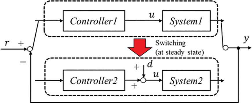
Switching system.
2.2. Control Law
The controllers for System1 and System2 use the following I-PD controller [Equation (1)].
Furthermore, the control error e(k) is calculated as the following Equation (2). r(k) is the reference value.
2.2.1. FRIT method
The controller1 for system1 is set as Kp1, Ki1, and Kd1 using the FRIT method. Here, Kp1, Ki1, and Kd1 are proportional gain, integral gain and differential gain, respectively. The controller parameters are calculated directly by using a set of operational data, and the block diagram is shown in Figure 2. u0(k) and y0(k) in the closed-loop data are system input and output of a set of initial operational data.
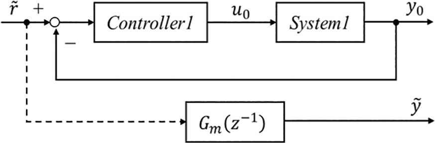
Block diagram of the FRIT method.
Here, p1 and p2 are designed by the following Equation (6) [2].
2.2.2. Fictitious Exogenous Signal method
The controller2 for system2 is set as Kp2, Ki2 and Kd2 by a method using the Fictitious Exogenous signal. Here, Kp2, Ki2 and Kd2 are proportional gain, integral gain and differential gain, respectively. The controller parameters are calculated directly by using a set of operational data. The method using the Fictitious Exogenous Signal is similar to the FRIT method, and block diagram is shown in Figure 3. The reference model Gmd(z−1) means the desired closed-loop transfer characteristics from disturbance to control error. d(k) is the input, and e0(k) is the output. The
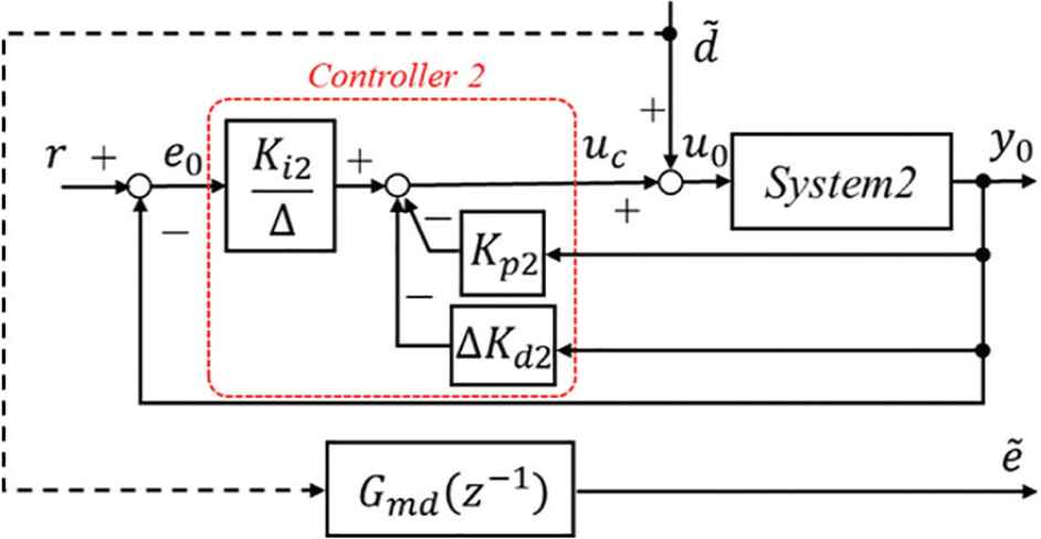
Block diagram of the proposed method using the Fictitious Exogenous Signal.
The reference model Gmd(z−1) can be expressed by the following Equation (8) using the Gm(z−1) in the FRIT method.
Therefore, output
The setting method of Pd(z−1) is the same as the FRIT method, and parameters σ and δ can be set different values from system1.
2.3. Genetic Algorithm
The GA was used to minimize the value of the evaluation function [4,5]. The evaluation function is defined by the following Equations (10) and (11).
N1 and N2 indicate the total number of steps of operational data in the system1 and the system2, respectively. In the system1, a desired response characteristic can be obtained by defining the difference between the reference model output
First, initial individuals Kp, Ki and Kd as genes are randomly generated, and initial evaluation is performed. Individual with high fitness are considered elite, and carry over to the next generation. Next, crossover, tournament selection and mutation are performed based on the evaluation values. These procedures are repeated in each generation, and PID parameters are obtained as the gene of the individual with the highest fitness in the final generation. In this paper, the GA was calculated using Matlab under the condition of 200 individuals and 200 generations.
3. NUMERICAL SIMULATION
To verify the effectiveness of the proposed method, a switching system of the first order lag systems was set as the following Equations (12) and (13) and a simulation was performed.
3.1. Conventional Method (CHR Method)
The following Equations (14) and (15) were calculated by discretizing the equations above at the sampling time Ts = 1 s, and are obtained, respectively. Here, the Gaussian white noise with mean 0 and variance 0.01 was given by ξ(k). Furthermore, in 250 steps, the system was switched from the system1 to the system2. The effectiveness of the proposed method was verified. Reference is r(k) = 10.
First, a simulation result using PID parameters calculated by the CHR method was shown in Figure 4. The PID parameters are shown in Table 1.
| Kp | Ki | Kd | |
|---|---|---|---|
| Systems1 and 2 | 3.0 | 0.06 | 3.0 |
PID parameters calculated by the CHR method
In Figure 4, it took long time to follow the Reference r(k), and the responsiveness of the system1 is not good. The fixed PID parameters corresponding to the system1 has particularly small proportional gain Kp. Therefore, input u(k) is moderate at the switching time, and the output variation after switching to the system2 is large and recovery time is long. The control performance is not good.
Simulation result by the CHR method.
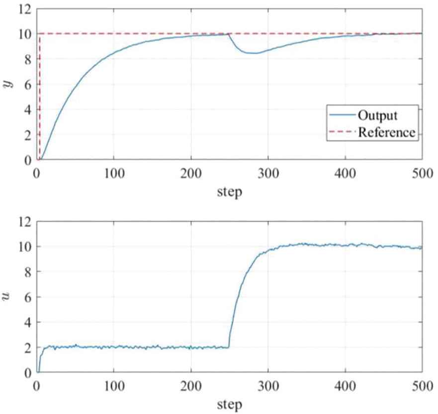
3.2. Proposed Method
Figure 5 shows the control result of the proposed method. The PID parameters for the system1 are calculated using the FRIT method, and the PID parameters for the system2 are calculated by adjustment method using the Fictitious Exogenous Signal. u0(k) and y0(k) that obtained by the CHR method were used as a set of the operational data in order to calculate the PID parameters for the system1 and the system2. Table 2 shows the PID parameters. As shown in Figure 5, the response of the system1 is faster than the conventional method, and the desired output was obtained. In addition, the output variation after switching to the system2 is less than 1/4 as compared with the conventional method, and good control performance is obtained. The PID parameters for system2 is larger than that for system1. Therefore, the response of input u(k) is faster and output variation can be suppressed.
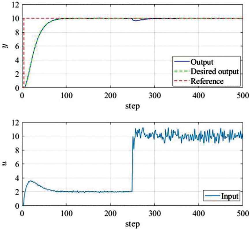
Simulation result using the FRIT method and the Fictitious Exogenous Signal.
| Kp | Ki | Kd | |
|---|---|---|---|
| System1 | 1.60 | 0.07 | 3.19 |
| System2 | 18.4 | 0.73 | 20 |
PID parameters calculated by the FRIT method and Fictitious Exogenous Signal
It was confirmed that the responsiveness after the system switching was improved by considering the system fluctuation as a disturbance input and applying the adjustment law using the Fictitious Exogenous Signal.
4. CONCLUSION
In this paper, a method of controller adjustment law using the Fictitious Exogenous Signal for a system that switched characteristics in steady state was proposed. In the proposed method, the system fluctuation was regarded as a disturbance input, and the transfer function from the disturbance d(k) to the control error e(k) was constructed as the reference model Gmd(z−1). The Fictitious Exogenous Signal calculated from a set of operational data was input to the reference model Gmd(z−1). It was confirmed that a controller with a good disturbance responsiveness can be obtained by adjusting the PID parameters to approximate the reference model output
In the future, the proposed method will be applied to an actual machine to confirm the effectiveness.
CONFLICTS OF INTEREST
The authors declare they have no conflicts of interest.
Authors Introduction
Mr. Masatoshi Kozui
 He received his B. Eng. and M. Eng. from Hiroshima University in Japan in 2009 and 2011, respectively. He joined KOBELCO Construction Machinery Co., Ltd. in 2011. He is currently an Assistant Professor of Collaborative Research Laboratory with the Graduate School of Engineering, Hiroshima University, Japan. His research interests are skill evaluation and system control of Hydraulic Excavator.
Dr. Takuya Kinoshita
 He received his B. Eng., M. Eng. and D. Eng. from Hiroshima University in Japan in 2013, 2015 and 2017, respectively. He was postdoctoral fellow of Japan Society for the Promotion of Science (JSPS) in 2017. He is currently an Assistant Professor with the Department of System Cybernetics, Graduate School of Engineering, Hiroshima University, Japan. His research interests are performance driven control.
Prof. Toru Yamamoto
 He received the B. Eng. and M. Eng. degrees from the University of Tokushima, Tokushima, Japan, in 1984 and 1987, respectively, and the D. Eng. degree from Osaka University, Osaka, Japan, in 1994. He is currently a Professor with the Department of System Cybernetics, Graduate School of Engineering, Hiroshima University, Japan. He was a Visiting Researcher with the Department of Mathematical Engineering and Information Physics, University of Tokyo, Tokyo, Japan, in 1991. He was an Overseas Research Fellow of the Japan Society for Promotion of Science with the University of Alberta for 6 months in 2006. His current research interests are in the area of data-driven control, and process control. Dr. Yamamoto was the recipient of the Commendation for Science and Technology by the Minister of Education, Culture, Sports and Technology in 2009.
REFERENCES
Cite this article
TY  - JOUR
AU  - Masatoshi Kozui
AU  - Takuya Kinoshita
AU  - Toru Yamamoto
PY  - 2019
DA  - 2019/09/11
TI  - Design of a PID Controller using a Fictitious Exogenous Signal for a Fluctuation System
JO  - Journal of Robotics, Networking and Artificial Life
SP  - 118
EP  - 122
VL  - 6
IS  - 2
SN  - 2352-6386
UR  - https://doi.org/10.2991/jrnal.k.190828.010
DO  - 10.2991/jrnal.k.190828.010
ID  - Kozui2019
ER  -