
Influence of Safe Driving Support System for Electric Wheelchair on Operation Input
- DOI
- 10.2991/jrnal.k.191202.006How to use a DOI?
- Keywords
- Electric wheelchair; degree of collision risk; fuzzy reasoning; laser range finder
- Abstract
This paper describes the influence on operation input which is given by a safe driving support system for an electric wheelchair. A wheelchair is rapidly introduced as a mobility for elderly people who has disabilities on walking. Along with that, collision accidents of the wheelchair also increase and many causes are mistakes of operation and recognition of a driver. Therefore we developed the safe driving support system which contains a Laser Range Finder (LRF) and Ultrasonic Sensors (USSs) for obstacle detection. The wheelchair avoids the collision based on degrees of collision risk which is calculated based on fuzzy reasoning from control input of joystick and the distance for obstacles measured by the LRF and USSs. The system not only affects motion of the wheelchair, but also the driver’s condition and judgement for driving. We confirmed that the system enhances a controllability and safety, and influences operation input of driver from some experimental results.
- Copyright
- © 2019 The Authors. Published by Atlantis Press SARL.
- Open Access
- This is an open access article distributed under the CC BY-NC 4.0 license (http://creativecommons.org/licenses/by-nc/4.0/).
1. INTRODUCTION
In recent years, aging becomes serious problem, especially in Japan, population of 65 years and over has exceeded 27.7% [1]. And, it is expected to increase a population aging rate more than 38.8% at 2050. Along with that, wheelchairs are rapidly introduced as a mobility for elderly people who has disabilities on walking, and collision accidents of wheelchairs also increase [2,3]. Here, some accidents cause by mistakes of operation and recognition at driving, and these are expected to avoid the collision by engineering approach.
Several types of control method and supporting systems for automatic wheelchair has been proposed for safe driving. And, it is well known that cognitive speed and motion capability decline with aging [4,5]. Therefore, the safe driving support system is designed to compensate recognition or emergency responses of driver. Matoba and Sugaya [6] proposed a presenting method of blind spot image information for driver. Kiso et al. [7] proposed obstacle avoidance control method using fuzzy controller and ultrasonic sensors. Kokubo and Shibanoki [8] suggests a novel obstacle detection method for wheelchairs using impedance model. These researches mainly focus on improving safe performances and does not consider enough the driver’s intention and automation surprise.
Our developed wheelchair is controlled based on degree of collision risk which is calculated by fuzzy reasoning from obstacle locations [9]. Obstacles surrounding the wheelchair is detected by a Laser Range Finder (LRF) and Ultrasonic Sensors (USSs). The LRF is mounted in front and six USSs are mounted left, right and rear side of the wheelchair. In order to achieve both comfort operation and safety without automation surprise, the degree of collision risk for forward is calculated from a time to collision which is depending on distance to obstacle and velocity of the wheelchair. On the other hand, the degree of collision risk for backward is calculated from distance to obstacles for secure braking.
The system adjusts the control input of the motor to be safer in consideration of the sensor information and operation input by the driver. Here, due to the change in behavior of the wheelchair by the system, information obtained by the driver also changes, and it is considered to affect the operation input. Usefulness and safety of the proposed system are evaluated from trajectories of the wheelchair, joystick input and distance to obstacles of some experimental results. Moreover, we discussed about the influences of the proposed system for operation input by beginner and expert drivers.
2. DEVELOPED ELECTRIC WHEELCHAIR
Figure 1 shows the developed electric wheelchair which is based on “Intelligent Wheelchair” Emu-S by WACOGIKEN (1-1-50 Suehiro-cho, Tsurumi-ku, Yokohama, Kanagawa, Japan). The wheelchair is driven by independent two brushless DC motors and operated by a joystick. Table 1 shows specifications of the motor. The control unit and motor driver of the wheelchair is replaced to our developed circuits for precise control. A LRF and six USSs are mounted to measure obstacle information.
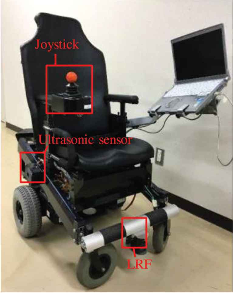
Appearance of electric wheelchair.
| Supply voltage (V) | DC 24 |
| Rated output (W) | 300 |
| Rated rotation speed (/min) | 3000 |
| Rated torque (Nm) | 1.43 |
| Rated current (A) | 21 |
| Max. current (A) | 42 |
Specification of motor
The joystick outputs analog voltage signals which corresponds to tilt angles of x and y axes of it.
The LRF is mounted in front of the wheelchair and measures the distances to front obstacles as digital signals. The system calculates distances dRE, dRF, dLF and dLE to reduce computation cost, which are the shortest distance in the area divided areas into right–left and front-edge as shown in Figure 2.
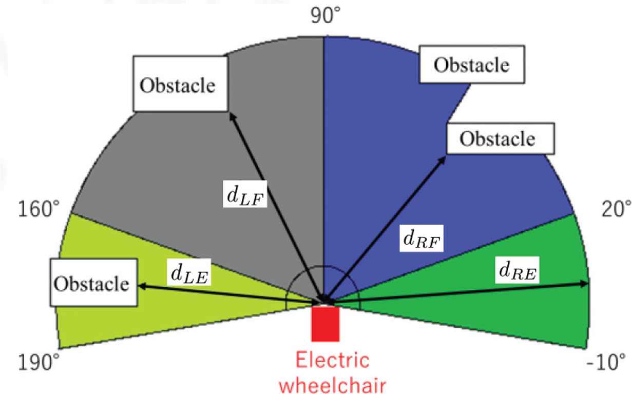
Detection range of LRF.
Six USSs are mounted on left, right and rear side as shown in Figure 3a, and a detection range of the USS is shown in Figure 3b. The USSs output analog voltages according to distance of obstacles dRS, dRD, dRB, dLB, dLD and dLS for each direction. Specifications of the LRF and the USS are shown in Tables 2 and 3.
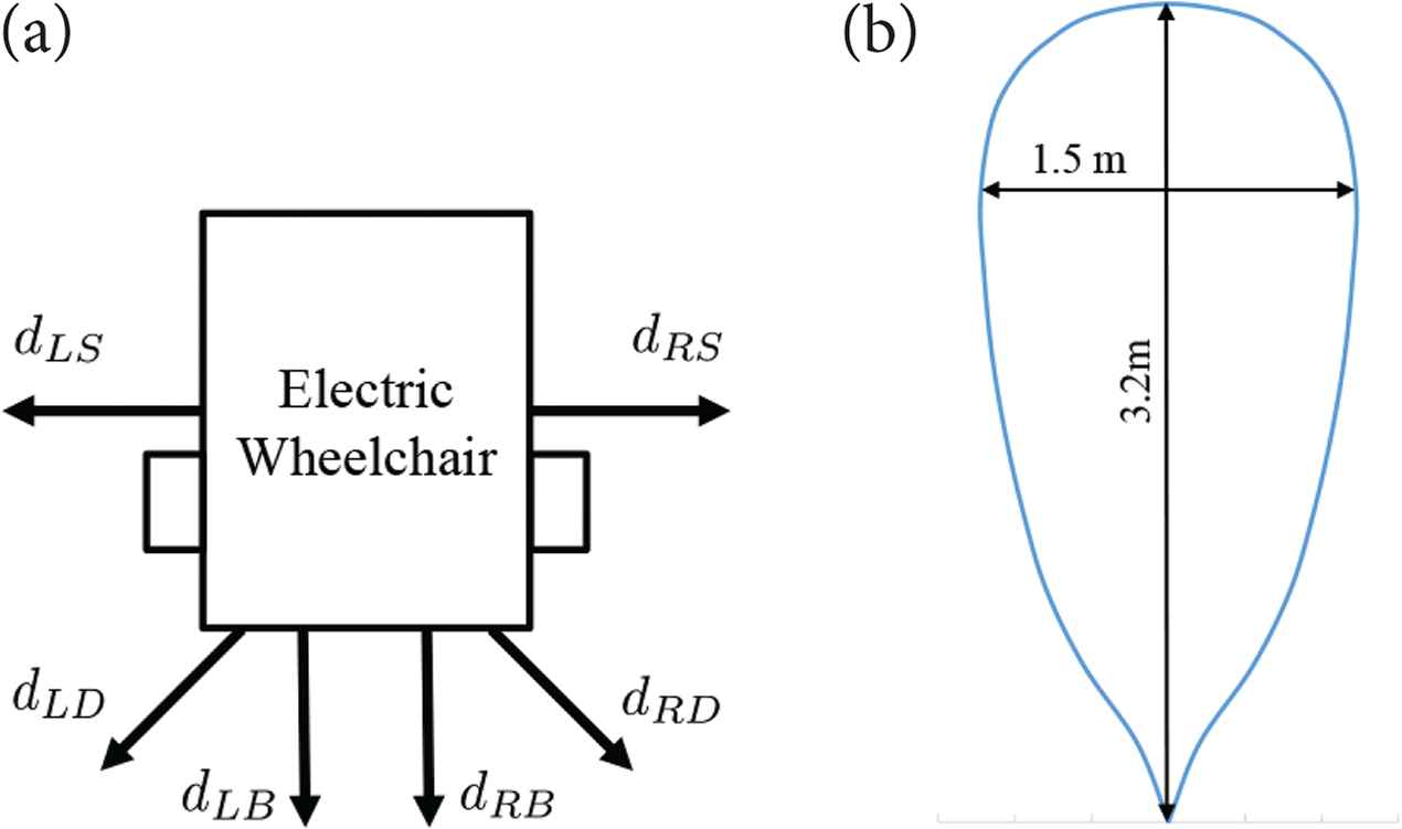
Detection range of USS. (a) Mount position. (b) Detection range.
| Supply voltage (V) | DC 24 |
| Detection range (m) | 0.06–10 |
| Detection angle (°) | 270 |
| Sampling time (ms) | 25 |
| Angle resolution (°) | 0.25 |
Specification of LRF (UST-10LX)
| Supply voltage (V) | DC 5 |
| Detection range (max.) (m) | 0.015–6.45 |
| Sampling time (ms) | 50 |
Specification of USS (MB1010)
3. SAFE DRIVING SYSTEM
Hardware configuration of the safe driving support system is shown in Figure 4. The system consists of a microcontroller, motor drivers, a joystick, six USSs, a LRF and a laptop PC. Output signals of the joystick and USSs are measured by a built-in A/D converter of microcontroller and send to the laptop PC via RS-232C communication. The LRF is connected to the laptop PC via TCP/IP communication and measures the distances to obstacles. The laptop PC calculates degrees of collision risk from the tilt angles of the joystick and the sensor values. Motor speed command is calculated by the microcontroller from the joystick input and the degrees of collision risk. Right and left motors are controlled to follow the motor speed command based on vector control.
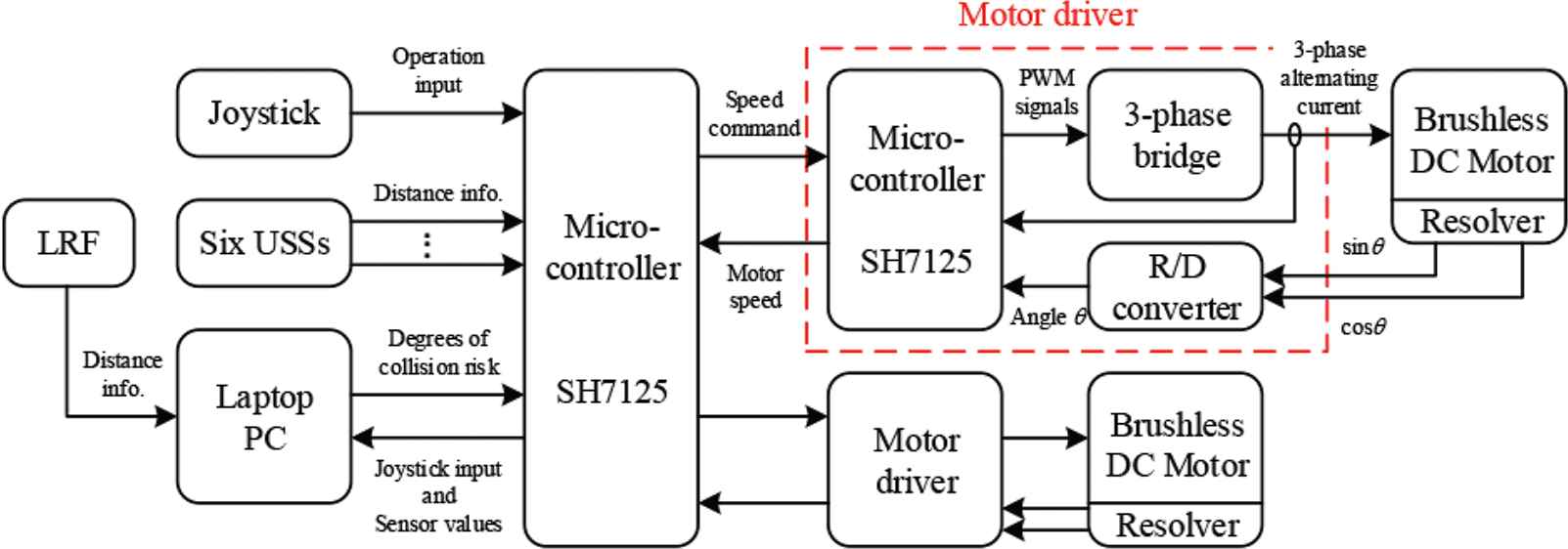
System configuration.
3.1. Degree of Collision Risk
The degree of collision risk on forward and backward moving are calculated by simplified fuzzy reasoning with different rules, which are designed for different control purpose. In the forward moving, the wheelchair is required to avoid obstacles as following the joystick input. On the other hand, in the backward moving, safe stopping for obstacles is the most important. Therefore, we defined seven degrees of collision risk αRF, αRS, αRB, αLF, αRS, αLB and αCB for each direction shown in Figure 5.
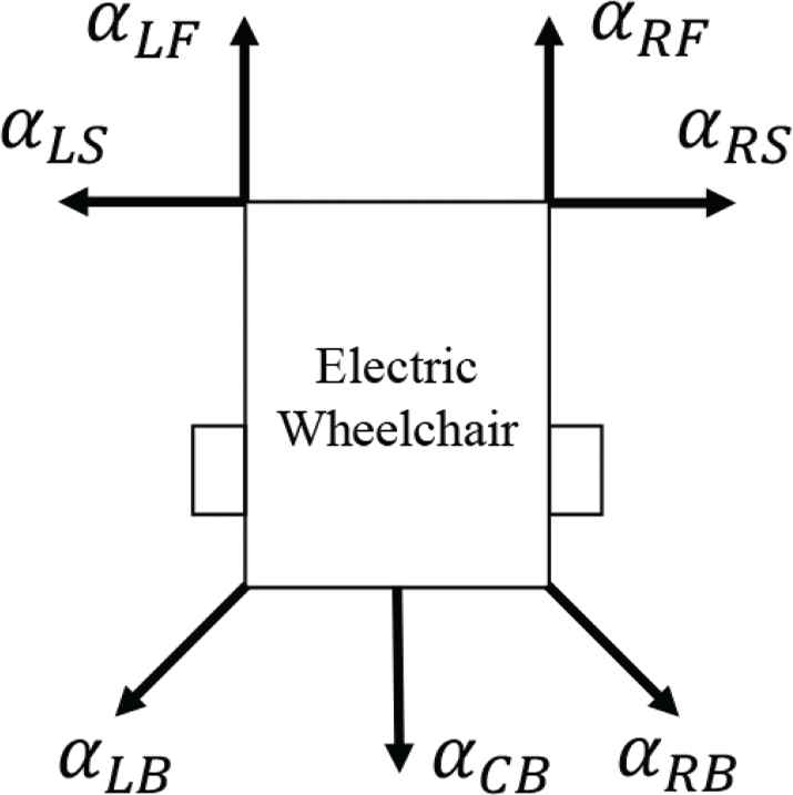
Degrees on collision risk.
3.1.1. Degree of collision risk on forward moving
In forward moving, the system makes human drive safety by limiting speed of wheels based on the degrees of collision risk. Figure 6 shows a calculation procedure of degrees of collision risk for forward moving. The degrees of collision risk are calculated respectively for each distances to obstacle dRS, dRE, dRF, dLF, dLE and dLS measured by the LRF and side USSs.
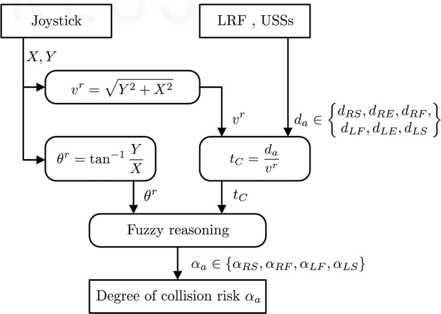
Control algorithm for forward moving.
The degree of collision risk on forward moving is calculated by fuzzy reasoning from the tilt direction of the joystick θr and a Time to Collision (TTC) tC. TTC is an allow time for collision at input speed command of the joystick vr and the distance to obstacle da. Here, the degree of collision risk αRS is decided as maximum degree of collision risk for distances dRS and dRE, to combine the measurement results of the LRF and USSs. And αLS is also decided from dLS and dLE as maximal value.
Figure 7a and b shows fuzzy sets for forward moving. The fuzzy set of TTC is designed in consideration of braking time of the wheelchair. And the fuzzy set for joystick is separated at 90° to decide the avoiding direction clearly. Fuzzy rules for forward moving is decided as shown in Table 4. These rules were decided by trial and error. Naturally, the rules for left and right side are symmetry.
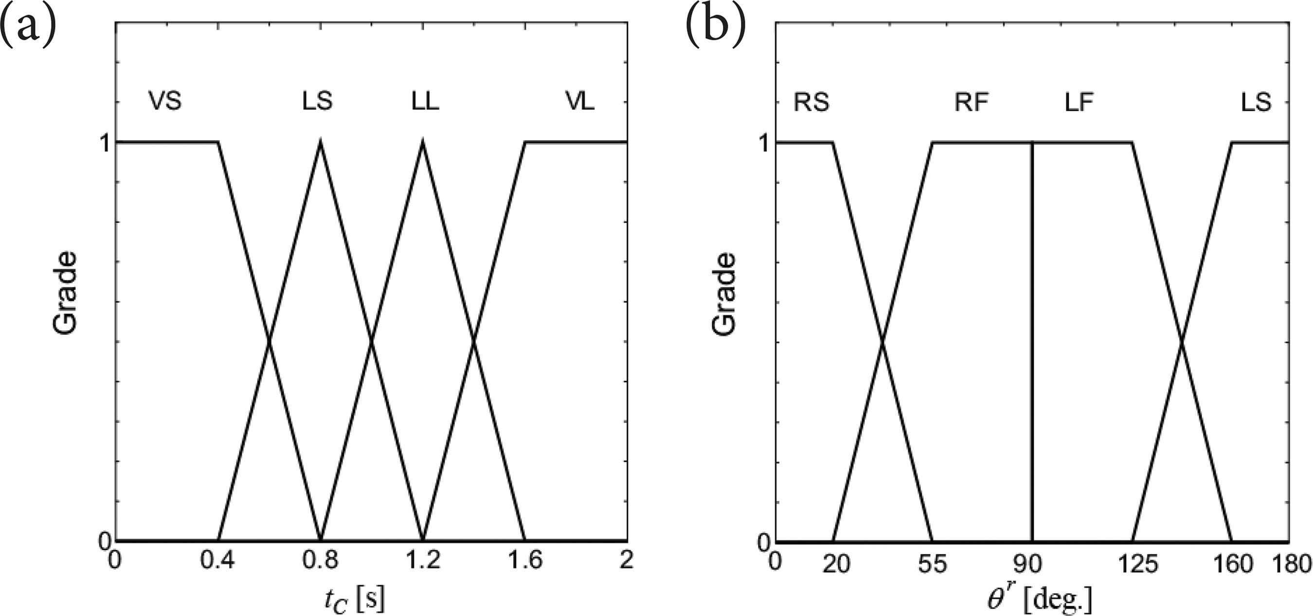
Membership functions for forward moving. (a) TTC. (b) Direction.
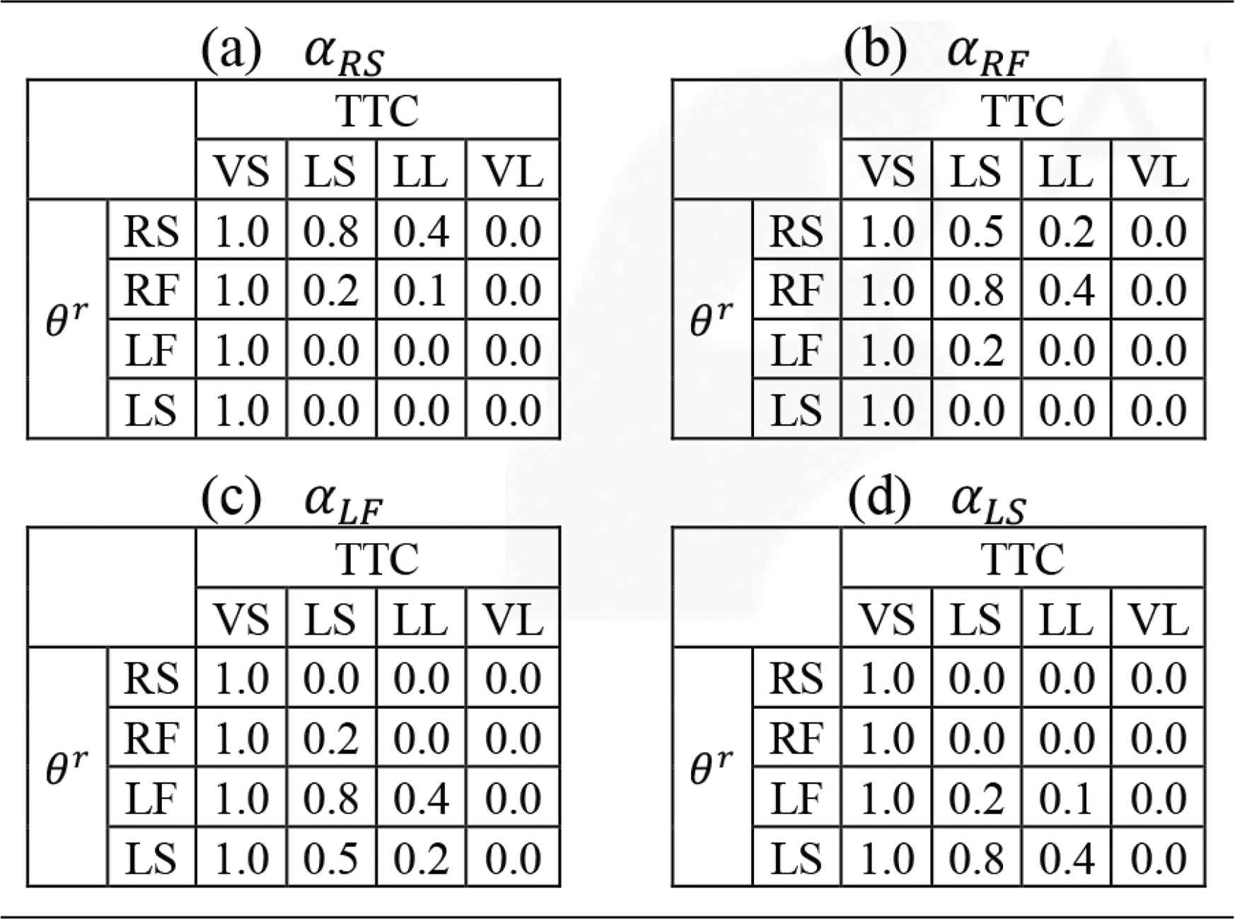
Fuzzy rules for forward moving
3.1.2. Degree of collision risk on backward moving
Figure 8 shows a calculation procedure of degrees of collision risk for backward moving. The distance to obstacles are measured by the six USSs.
The degree of collision risk on backward moving is calculated by fuzzy reasoning from the tilt direction of the joystick θr and the distance to obstacle da. In order to brake the wheelchair independently of the input speed from the joystick, the distance of obstacle were used. Similarly to the forward moving, αRB, αLB and αCB are respectively decided as maximal degree of collision risk for {dRS, dRD}, {dLS, dLD} and {dRB, dLB} to consider an overlap of measurement area.
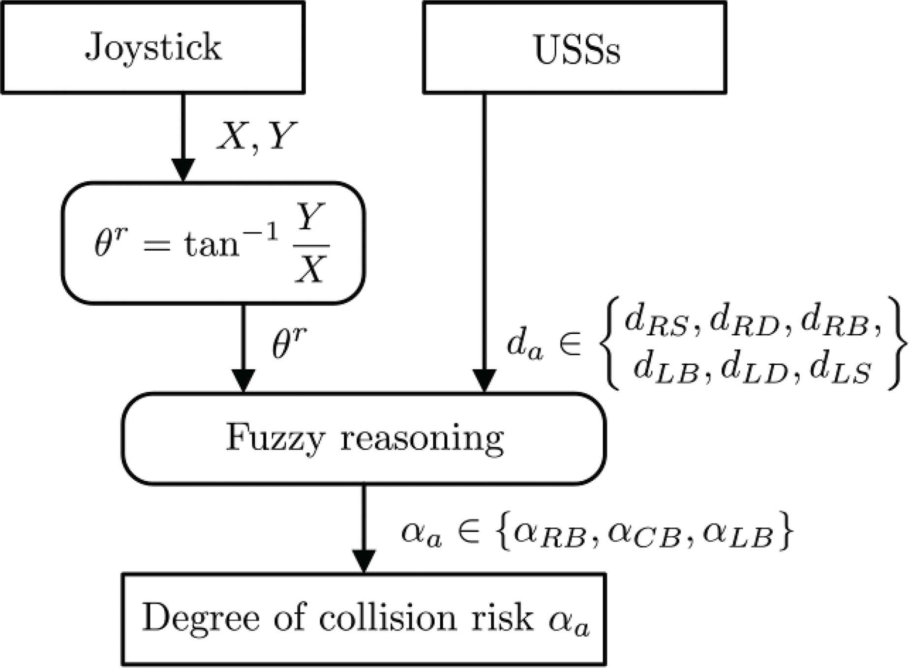
Control algorithm for backward moving.
Figure 9a and b shows fuzzy sets and Table 5 shows fuzzy rules for backward moving. The fuzzy set for the distance is designed in consideration of braking performance of the wheelchair. And the fuzzy set for the joystick is designed as change gradually, because a control purpose for backward moving is safe and smooth braking.
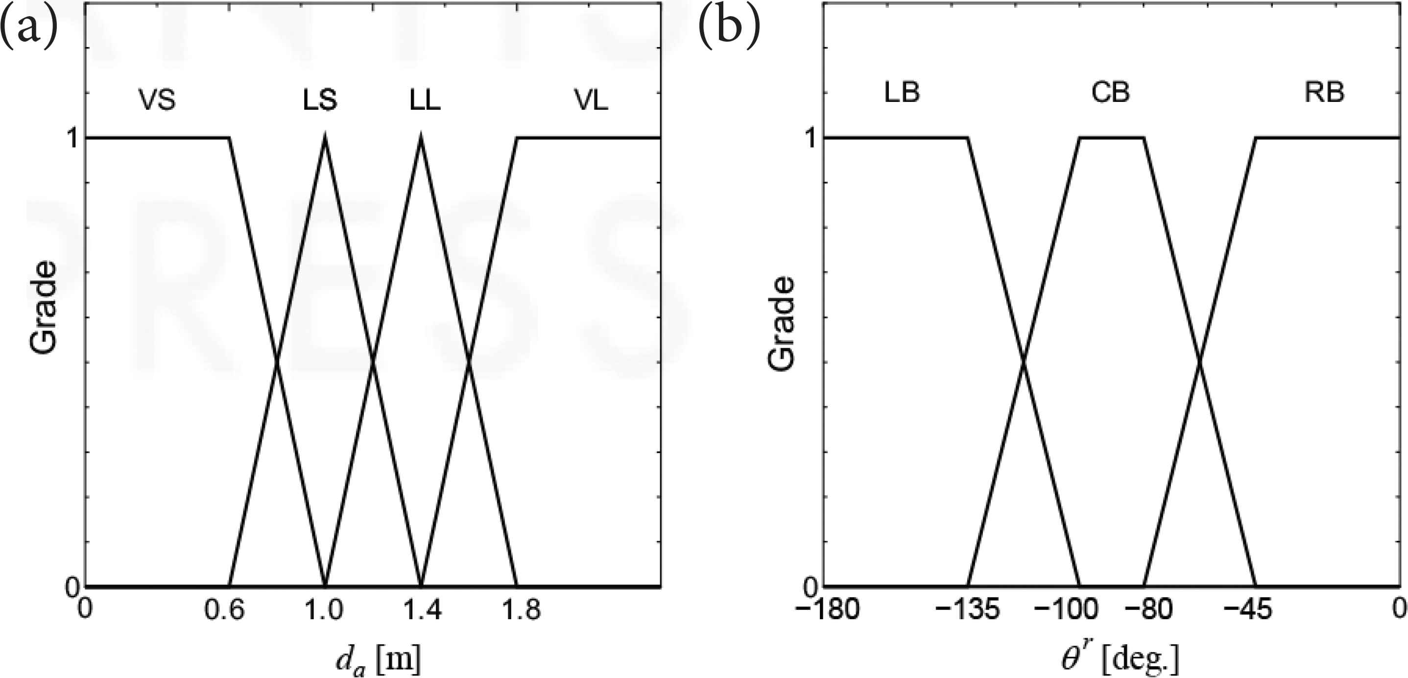
Membership functions for backward moving. (a) Distance. (b) Direction.
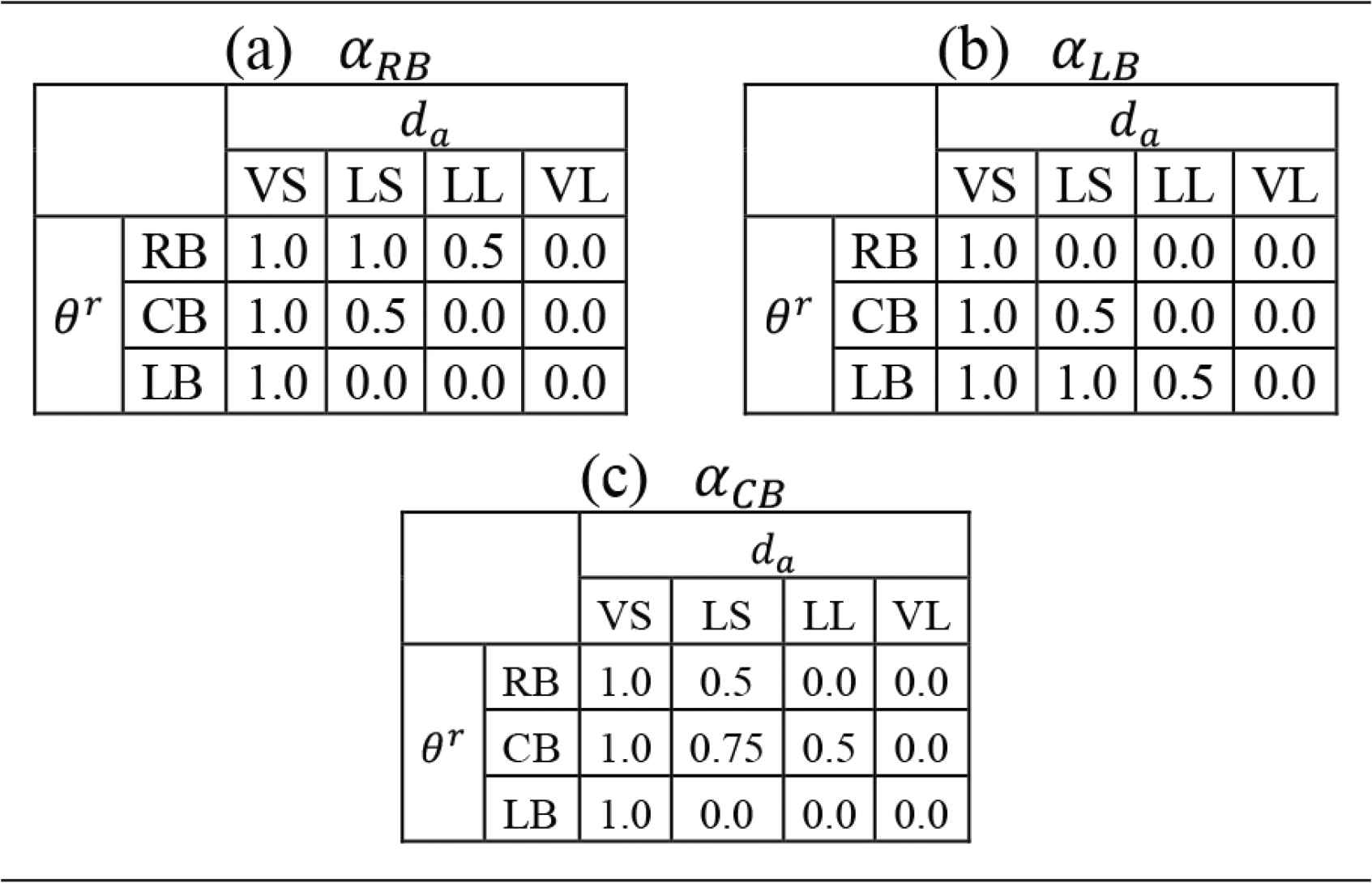
Fuzzy rules for backward moving
The use of fuzzy reasoner is excessive for only six USSs, because the measured directions of obstacle are discrete value. The fuzzy reasoner is designed in anticipation of introducing LRF for backward.
3.2. Limitation of Wheel Speeds
Generally, motor speed references
Then, we proposed the safe driving support system by limiting the motor speed references based on the degrees of collision risk by modifying the Equation (1). The motor speed is limited coefficients AYR, AYL and AX shown in Equation (2). The limited coefficients are selected from the degrees of collision risk on the basis of the joystick input.
In the forward moving (Y ≥ 0), the system changes a balance of right and left motor speed based on αLF and αRF to avoid obstacles with continuous advancing. Here, the system changes the direction of wheelchair smoothly by using the fuzzy reasoning to reduce uncomfortable feeling for drivers.
On the other hand, in the backward moving (Y < 0), the system limits the both motor speeds evenly based on αCB to avoid the collision by stopping. It is the result of considering the difficulty of human’s recognition for backward.
4. EXPERIMENTAL RESULTS
4.1. Experimental Setup
Figures 10 and 11 show an appearance and obstacle positions in experimental field. There are two static obstacles located in left and right side on passage alternatively. The wheelchair moves on the passage between obstacles with avoiding.
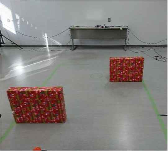
Appearance of experimental field.
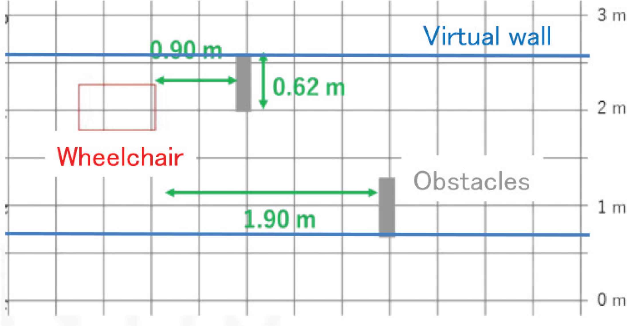
Obstacle positions in experimental field.
To validate the safe driving support system, two experiments forward and backward moving were conducted by two drivers A and B. Driver A is an experienced driver who knows characteristics of the wheelchair well. On the other hand, driver B is a beginner driver who is not practice driving before. All results are compared with the experimental results with and without the system.
Trajectories of the wheelchair is measured by motion tracking system OptiTrack which is a 3D position tracking system using infrared LED and cameras. By taking a pictures by eight infrared cameras, 3D position of markers are calculated. Four markers mounted on rods extended above from the wheelchair to reduce a dead zone.
4.2. Forward Moving
Figure 12a and b shows trajectories of experimental results for forward moving every 0.2 s by driver A. Both results with and without the system represents smooth and safety driving, and the speed becomes faster by using the system.
Figure 13a and b shows joystick inputs by driver A. In figures, black and red line show input signals of joystick for Y and X directions. In all the experimental results in this paper, the outlines of operation input in X directions changes in order of right, left and right to avoid two obstacles, although the differ scale and timing corresponding to driving condition. From Figure 13a, driver A decelerated the wheelchair at t = 1 s in the case of without system, and it is intended for obstacle avoidance. On the other hand, in Figure 13b, driver A did not decelerate because the wheelchair avoided obstacles automatically by the system before an avoiding operation. Therefore, trajectory of the wheelchair becomes safer and driving speed becomes faster by using the system.
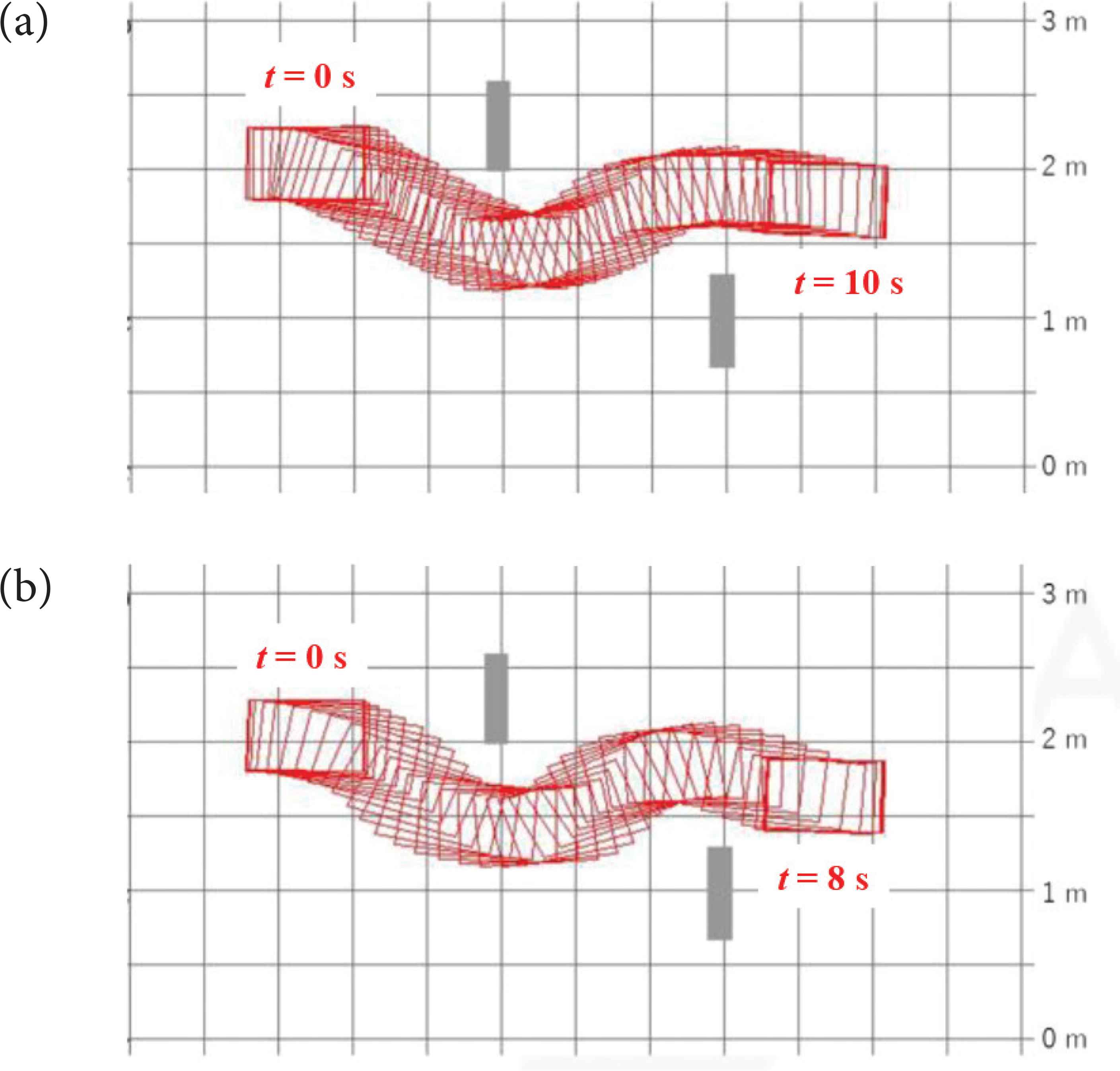
Trajectory on forward moving (driver A). (a) Without system. (b) With system.
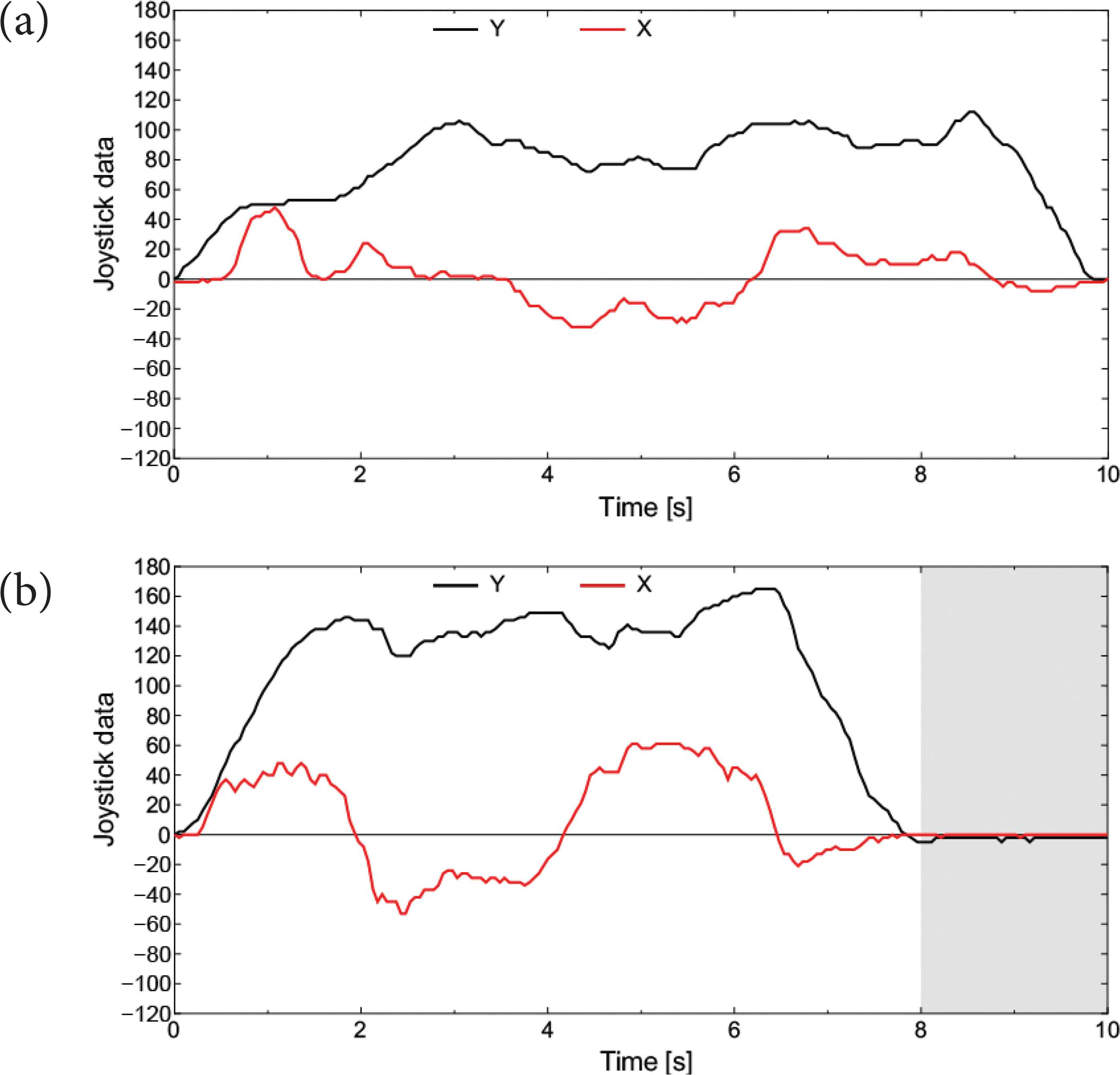
Joystick input on forward moving (driver A). (a) Without system. (b) With system.
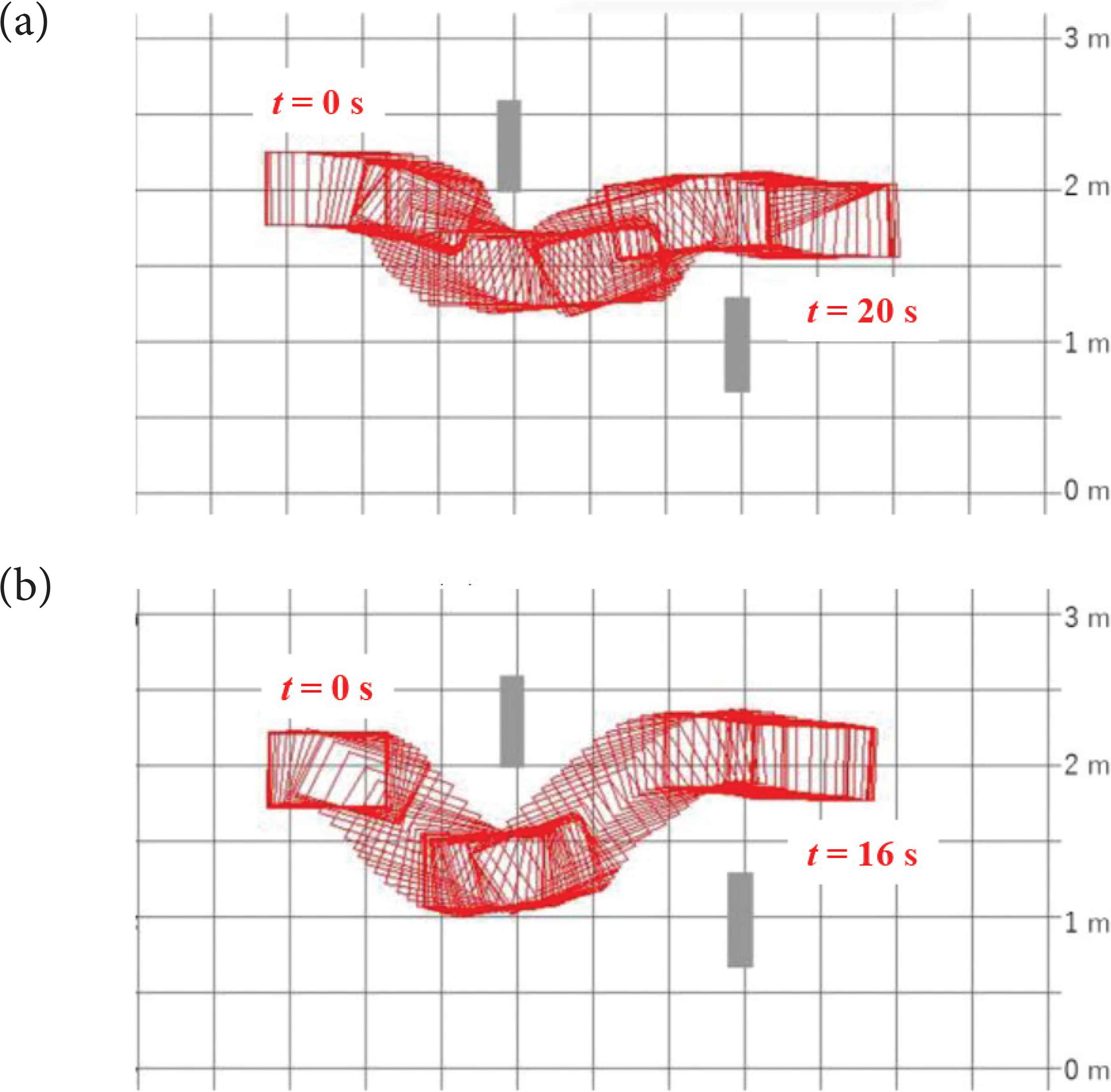
Figure 14a and b shows trajectories by driver B who is a beginner and Figure 15a and b shows joystick inputs. The trajectory in Figure 14a is not smooth and takes a lot of time. And from Figure 15a, it is confirmed that the driver frequently changes both X and Y joystick input to avoid obstacles. These are caused by the lack of time for the recognition, and control input becomes reactively and lagging.
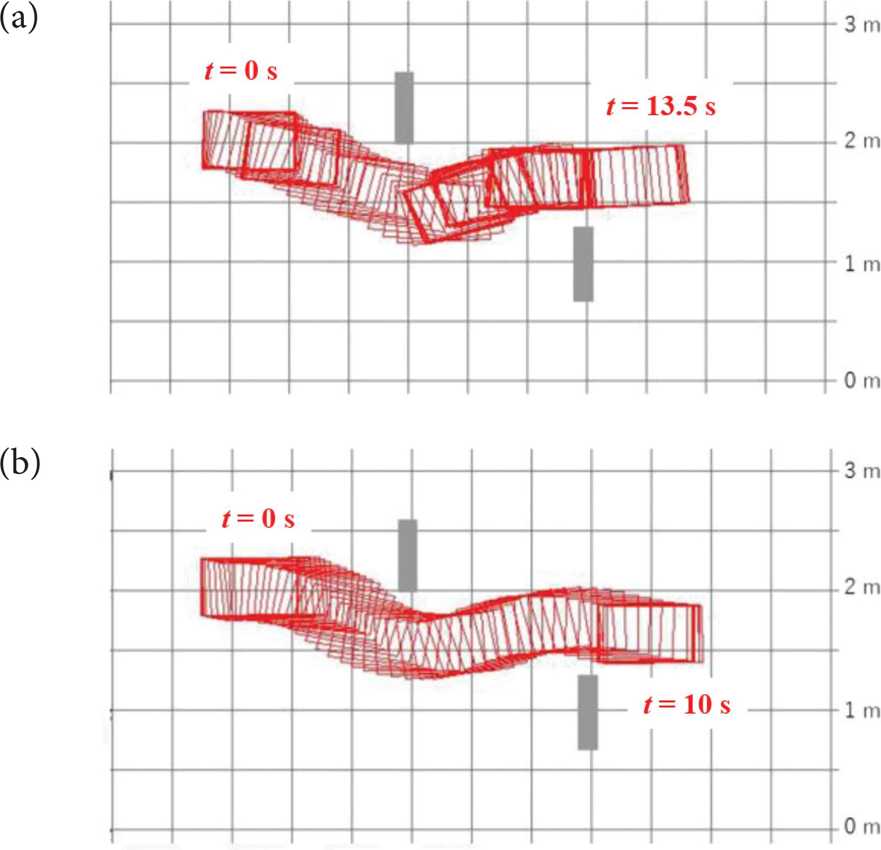
Trajectory on forward moving (driver B). (a) Without system. (b) With system.
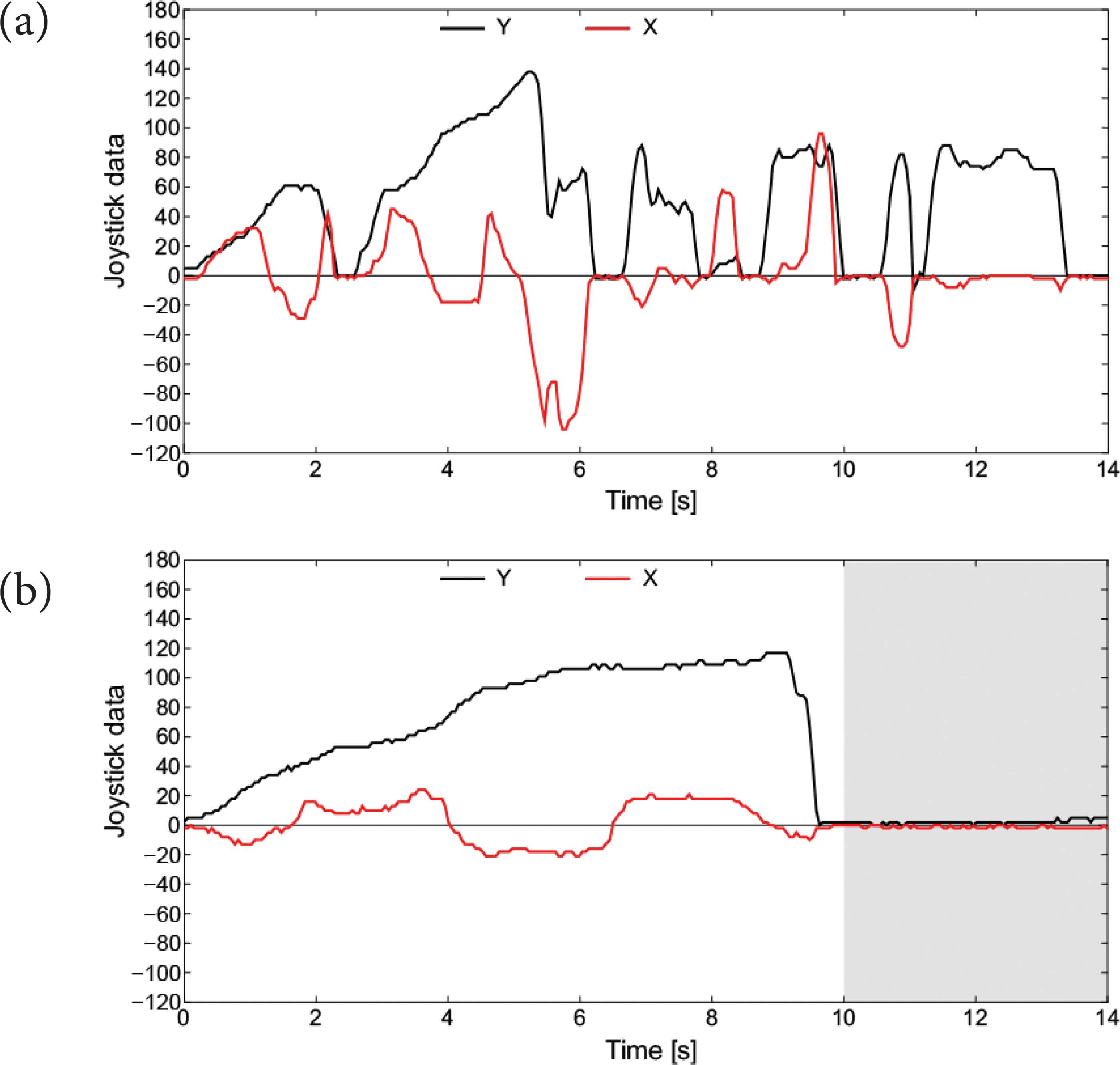
Joystick input on forward moving (driver B). (a) Without system. (b) With system.
On the other hand, the trajectory in Figure 14b becomes smooth and faster. Continuous joystick input is confirmed from Figure 15b, because there is allowance for operation by the automatic avoidance. As a proof, the driver B also did not input avoidance operation until t = 2 s in Figure 15b, but the wheelchair avoided the first obstacle as shown in Figure 14b. Moreover, in Figure 15b, the shape of the operation input in the Y direction by the beginner become continuous, similar to the expert shown in Figure 13a and b. We think that the speed suppression in the first half of Figure 15b is because beginner was wary of the first obstacle. It is a result of the proper speed suppression by the system, and the beginner driver obtained the time margin for obstacle recognition and avoidance. In belief, proposed system makes operation of the driver safe side.
4.3. Backward Moving
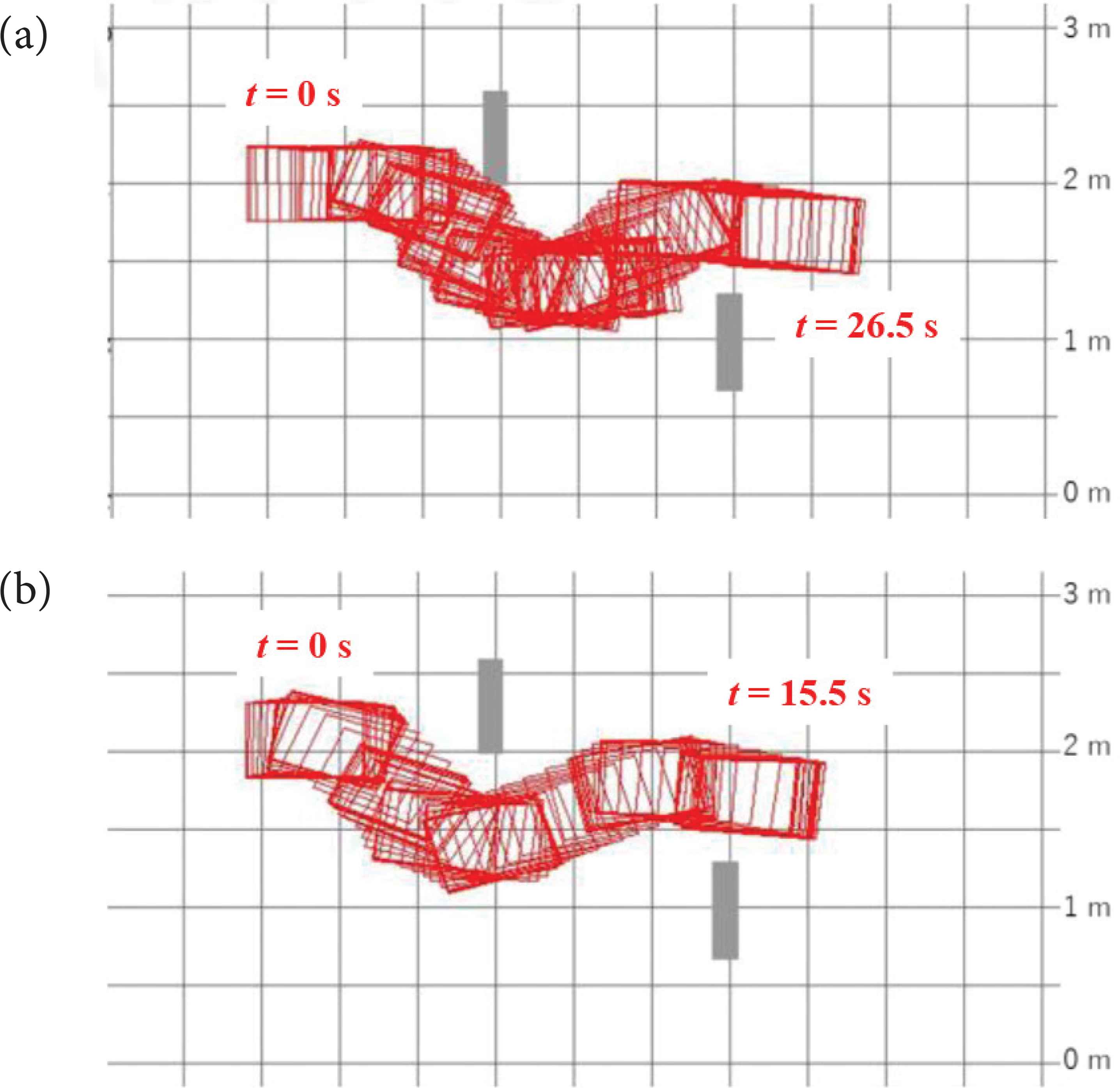
Figure 16a and b shows trajectories of experimental results for backward moving by driver A. In the case of without system, the wheelchair passes near the first obstacle in Figure 16a. However, in Figure 16b, the wheelchair kept distance from obstacles and passing safely.
Trajectory on backward moving (driver A). (a) Without system. (b) With system.
Figure 17a and b shows measured distances to obstacles by USSs. From comparison of the figures, the distance to obstacles increases by using the system. And the minimum distance to obstacles becomes from 215 to 518 mm.
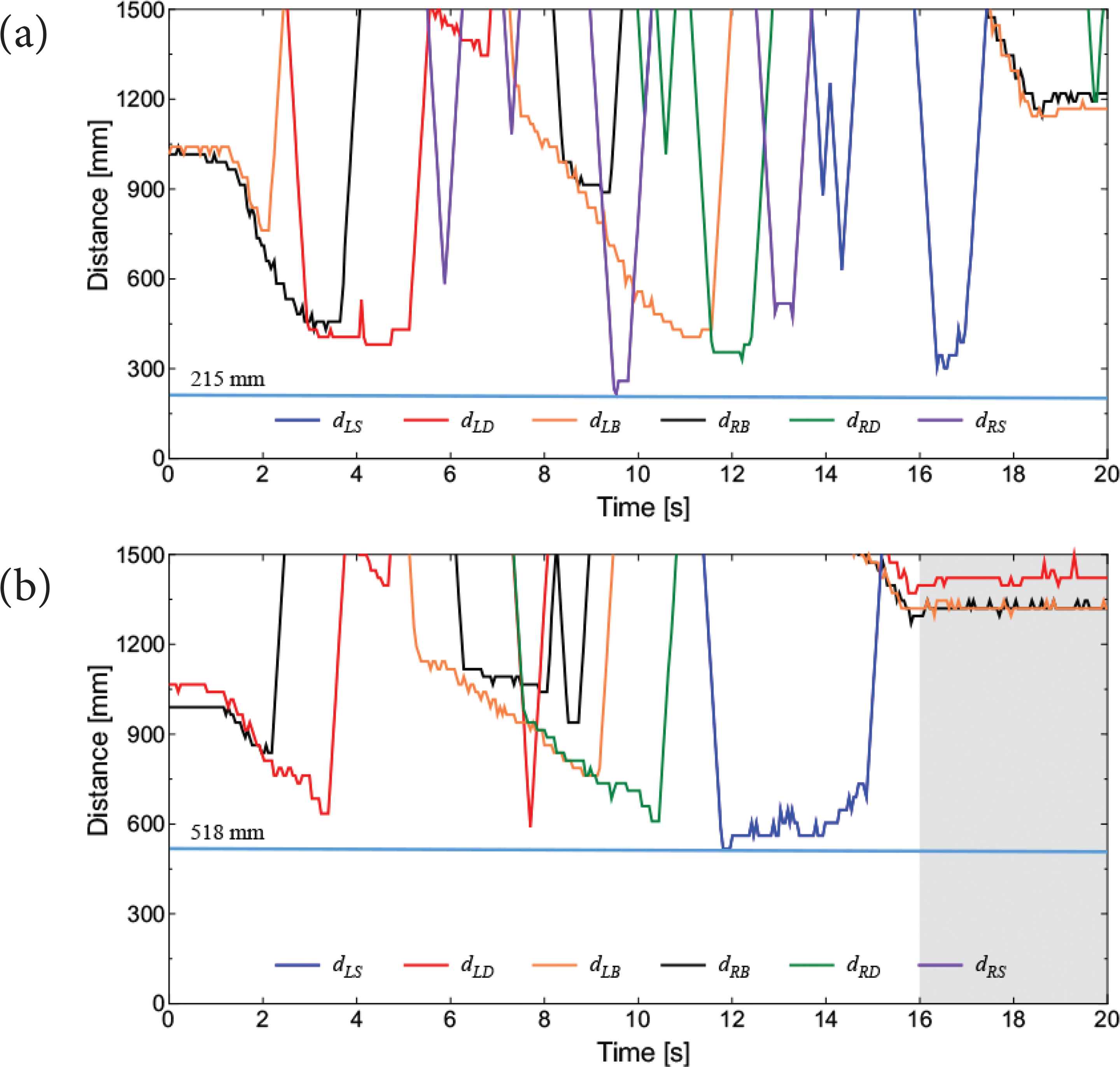
USS outputs on backward moving (driver A). (a) Without system. (b) With system.
Figures 18–20 show trajectories, measured distance to obstacles and joystick input for backward moving by driver B. In Figure 18a, the wheelchair looks almost collide to the first obstacle and the trajectory is not smooth. The minimum distance to obstacles is about 177 mm from Figure 19a. Here, these are distances from USSs, not from an edge of wheelchair.
Trajectory on backward moving (driver B). (a) Without system. (b) With system.
By using the system, although the trajectory is not smooth enough, but the moving speed is faster and the distance to obstacle becomes 330 mm in Figure 18b. Moreover, in Figure 20a, inputs of the joystick is intermittent and includes some forward command at from 17 to 19 s. On the other hand, in Figure 20b, the number of the intermittent input decreases and there are no forward command. And inputs of the joystick for X axis is also decreased and driving becomes more stable. These are results of the stopping control for obstacles by the system, and the beginner driver earn the recognition margin same to forward one.
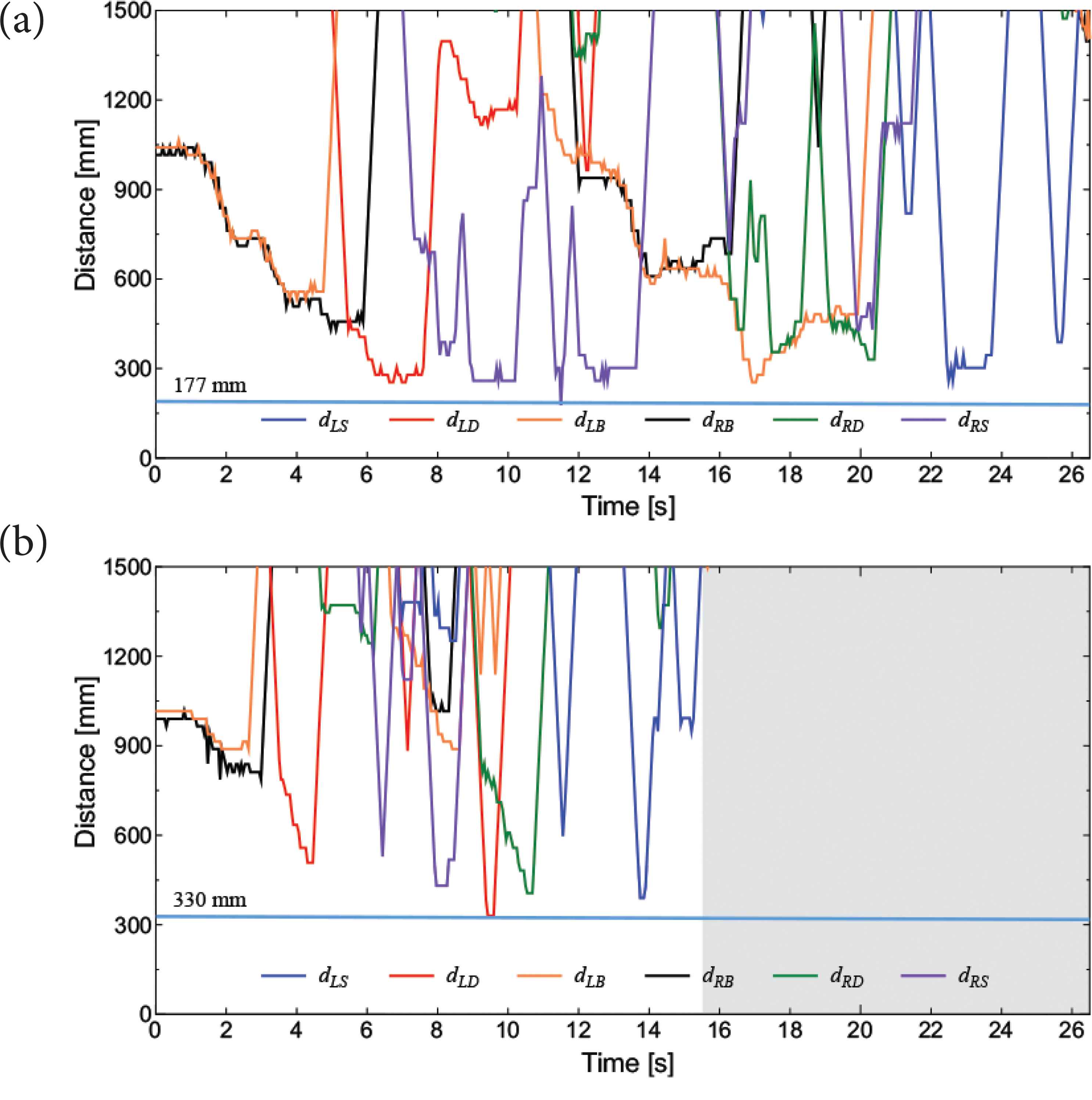
USS outputs on backward moving (driver B). (a) Without system. (b) With system.
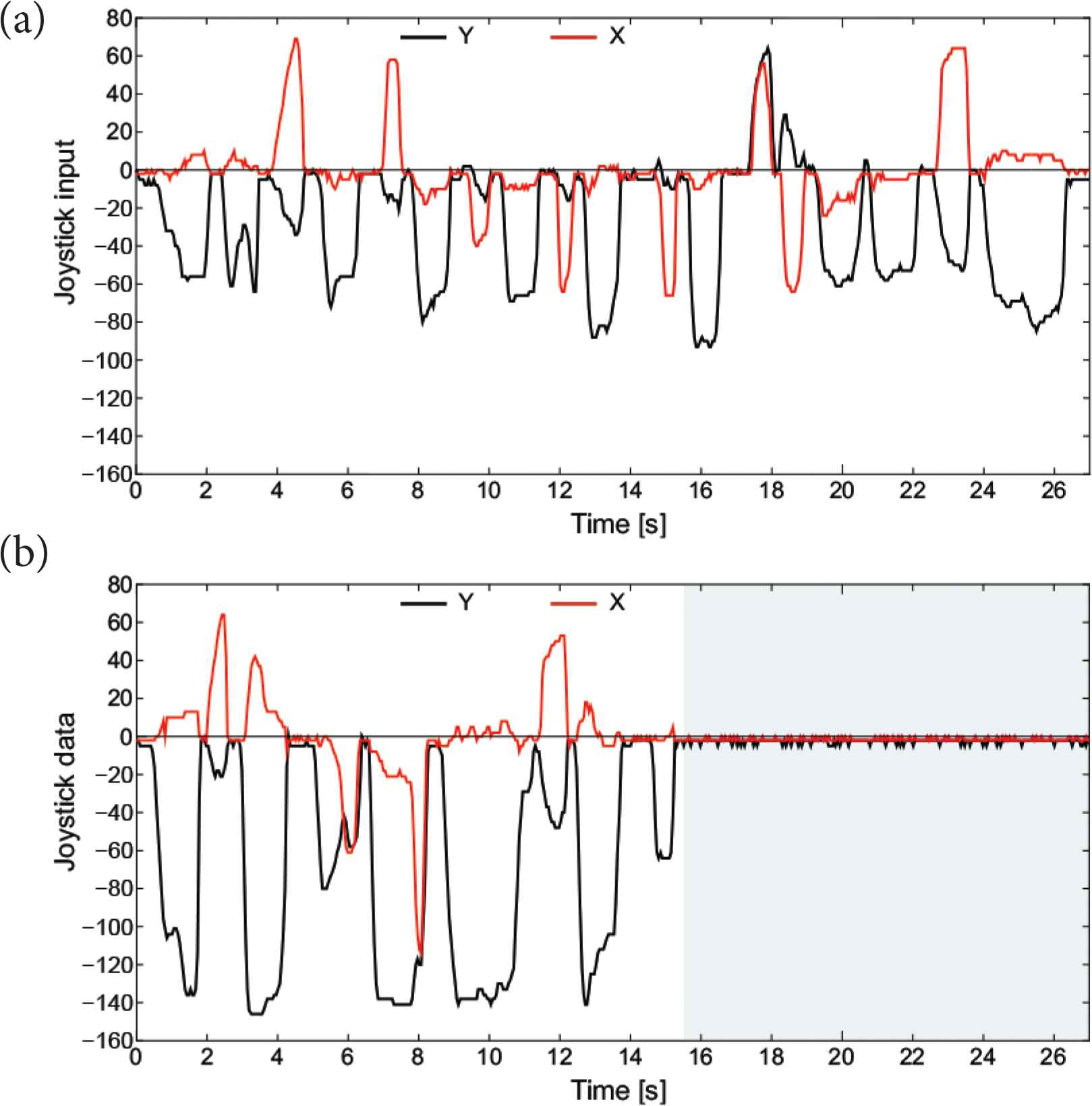
Joystick input on backward moving (driver B). (a) Without system. (b) With system.
From these results, we confirmed that it is difficult to recognize the obstacle located in rear side and to drive backward for the beginner. And it is similar to elderly person who is a main target of the electric wheelchair.
5. CONCLUSION
In this paper, we proposed a safe driving support system for electric wheelchair. From the distances of obstacles measured by the LRF and USSs, the degrees of collision risk is calculated by fuzzy reasoning. And the system suppresses the wheel speeds based on the degrees of collision risk in consideration of the joystick input.
Some experimental results demonstrate that the proposed system makes the wheelchair driving safe and easy. By using the system, not only the driving speed of wheelchair became faster, but also the distance to obstacles became far. And the frequent joystick input by driver for obstacle avoidance was decrease. Here, supporting effect is remarkable for beginner driver who is not trained operation and is not adjust to environmental recognition. Moreover, the same effect is expected for elderly people.
A future task is to evaluate the system from experiments by multiple subjects including elderly and physical disable people. And it is necessary to experiment in real environment such as a road and passage way with dynamic obstacles.
Authors Introduction
Dr. Hiroshi Suzuki
 He received his PhD degree from Tokushima University, Japan, in 2011. He is an Assistant Professor in the Faculty of Science and Technology, Tokushima University since 2016. His current research interests are intelligent control and sensor network. Dr. Suzuki is a member of the Institute of Electrical Engineering of Japan, and the Society of Instrument and Control Engineers.
Mr. Tomoki Matsuo
 He received his M.E. degree from Tokushima University, Japan, in 2019. His current research interest is human friendly mobility system. He is a student member of the Institute of Electrical Engineering of Japan.
Dr. Takashi Yasuno
 He received his PhD degree from Tokushima University, Japan, in 1998. He is a Professor in the Faculty of Science and Technology, Tokushima University since 2013. His current research interests are intelligent motion control systems. He is a member of the Society of Instrument and Control Engineers, the Institute of Systems, Control and Information Engineers, the Robotics Society of Japan, and IEEE.
REFERENCES
Cite this article
TY  - JOUR
AU  - Hiroshi Suzuki
AU  - Tomoki Matsuo
AU  - Takashi Yasuno
PY  - 2019
DA  - 2019/12/18
TI  - Influence of Safe Driving Support System for Electric Wheelchair on Operation Input
JO  - Journal of Robotics, Networking and Artificial Life
SP  - 171
EP  - 178
VL  - 6
IS  - 3
SN  - 2352-6386
UR  - https://doi.org/10.2991/jrnal.k.191202.006
DO  - 10.2991/jrnal.k.191202.006
ID  - Suzuki2019
ER  -