
Selection System of Robot Type for Cell Assembly Production (Production Efficiency Comparison of Single and Double Arm Robot)
- DOI
- 10.2991/jrnal.k.200528.001How to use a DOI?
- Keywords
- Genetic algorithm; unit arrangement decision; dual arm robot; assembly machine
- Abstract
The purpose of this research is to compare the production efficiency of single and double arm robot. This research determines which robot is suitable for an assembly cell production, a single arm robot or a double arm robot. First, we develop the system to use a double arm robot to determine the best parts location by Genetic Algorithm (GA). The system consists of two modules, the conditions module and GA module. The conditions module reads work data for robot and sets up various parameters required for GA. The GA module decides the efficient arrangement place of parts, jigs and robot hands by GA and outputs the acquired arrangement visual images. Next, we use a single arm robot at the same parts location and compare the working time with a double arm robot. Finally, we conclude which robot is suitable for an assembly cell judging from the results of a total robot working time.
- Copyright
- © 2020 The Authors. Published by Atlantis Press SARL.
- Open Access
- This is an open access article distributed under the CC BY-NC 4.0 license (http://creativecommons.org/licenses/by-nc/4.0/).
1. INTRODUCTION
In recent years, it has been demanded to produce a large quantity of products in a short time at the production site. Automations of the assembling works by robots has been also carried out. When developing an automatic assembly machine including robots, the production efficiency depends on the arrangement of each unit of the assembly machine. However, in many factories, the placement of units is based on the experienced engineers. It remains questionable whether the determined placement by the experienced engineers is really efficient. In this research, the layout decision system that assists unit layout determinations of an efficient cell type assembly machine is developed by using Genetic Algorithm (GA) [1]. The system compares the production efficiency of a single and a double arm robot and determines which robot is suitable for the assembly job.
2. CELL TYPE ASSEMBLY MACHINE
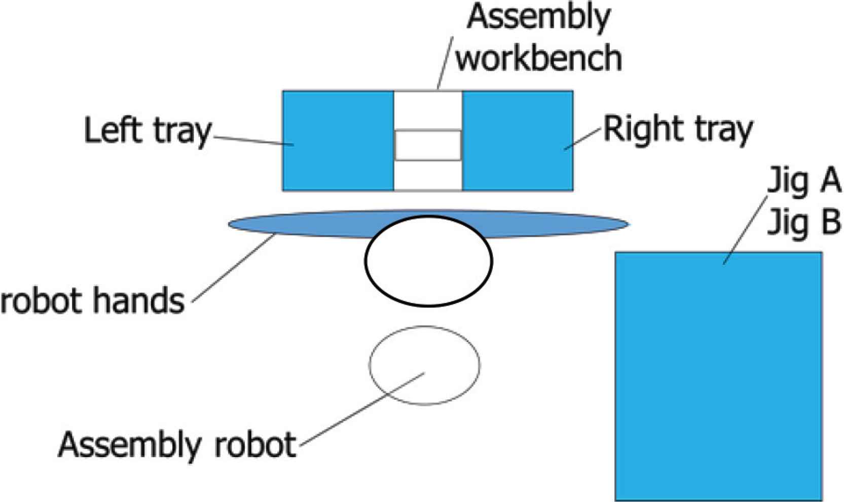
As shown in Figures 1 and 2, the cell type assembly machine to be used in this research has a configuration in which an assembly machine is arranged at the center, a work stand at the front and assembly units on the periphery. After each arm chucks the needed unit, the arm carries it to the workbench to assemble the parts. In the research, approach 1, approach 2 and the chuck position of the robot arm movement route are defined as the three points that exist on the arm moving route as follows:
- •
Chuck position: position for chucking and unchucking parts.
- •
Approach 1: position upward away from the chuck position.
- •
Approach 2: position further upward than approach 1.
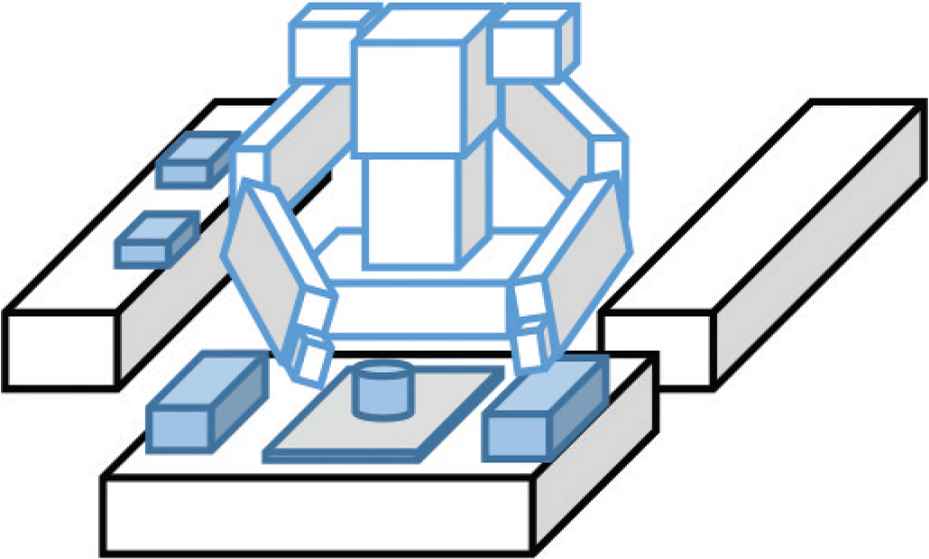
Cell type assembly machine of double arm robot.
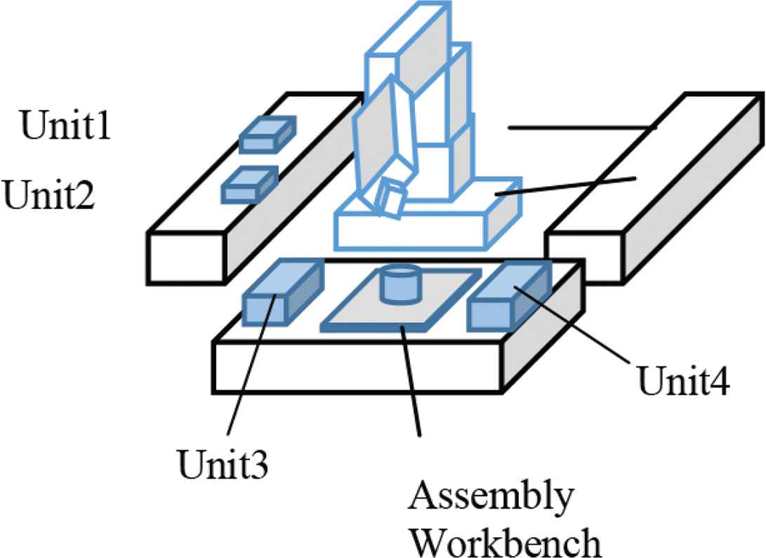
Cell type assembly machine of single arm robot.
As shown in Figure 3, the arm passes from approach 2 to approach 1 and arrives at the chuck position.
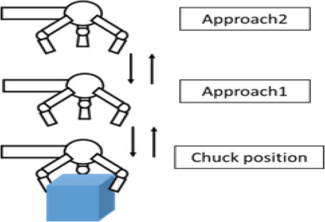
Movement of arm.
3. LAYOUT DETERMINATION SYSTEM
The layout decision system we develop decides the arrangement of each unit with the best operation efficiency during designing a cell type part assembly machine by using GA. The system consists of two modules, the condition creation module and the GA module. The condition creation module performs to read the arrangement possible area of the unit and work contents, to divide the arrangement possible area and to decide various necessary GA parameters. The GA module determines the arrangeable place of the units, evaluates the working time and outputs coordinates of the arrangement place of the unit and the layout image of the unit.
3.1. Condition Creation Module
The procedure of the condition creation module is as follows:
Step 1: Read work data of parts assembly, placement possible area, parts arrangement data and create their database.
Step 2: Divide possible placement area into a lattice shape to create possible placement place.
Step 3: Carry out genes coding.
Step 4: Define the fitness function.
Step 5: Determine various parameters.
3.2. GA Module
The process flowchart of the GA module is shown in Figure 4. The process procedure is shown below.
Step 1: Generate an initial population.
Step 2: Calculate the placement coordinates of each unit.
Step 3: Calculate the time taken for each work.
Step 4: Calculate fitness.
Step 5: Apply genetic operations (selection, crossover, mutation).
Step 6: Judge whether the termination condition is satisfied. If it is, go to Step 7. If not, go to step 3.
Step 7: The unit arrangement of individuals with the smallest operation time is adopted as the optimum arrangement and the output as a solution.
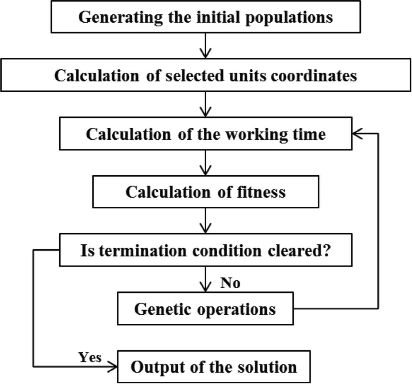
Flowchart of GA module.
A single arm robot comparison procedure.
Step 1: Calculate the unit optimal placement coordinates for ten times and each work time with a double arm robot using GA.
Step 2: The same work is performed on the industrial robot with the optimal placement coordinates for ten times obtained with the double arm robot, and the work time for each ten times is obtained.
Step 3: Compare work times obtained by both robots to find work efficiency.
Step 4: Determine which robot is suitable for cell-type automatic assembly production from the comparison of work time and efficiency.
Using the results of the double arm robot above mentioned, the single arm robot performs the same work above. The single arm robot is set with the same conditions such as the arrangement coordinates and the work process and arm speeds. As shown in Figure 2, the robot arm approach speeds are changed. Table 1 shows the both robot speed.
| Do not have parts (mm/s) | Have parts (mm/s) | |
|---|---|---|
| Approach 2–2 | 770 | 380 |
| Approach 2–1 | 400 | 250 |
| Approach 1–chuck | 25 | 50 |
Each arm speed
4. APPLICATION EXAMPLES AND PERFORMANCE COMPARISONS
The layout decision system was applied to the assembly machine and the production simulations were carried out. As a comparison, simulations of the following two systems were carried out.
- •
The system that determines unit layout by GA.
- •
The same work with a double and a single arm robot.
The units that needs to determine the placements have eight left tray, right part tray, left parallel hand, left three nail hand, right parallel hand, right four nail hand, jig A, jig B and also the assembly work. The layout map is shown in Figure 5. Figure 6 is the left and right part trays with 52 parts. Each number represents each part.
Units layout.
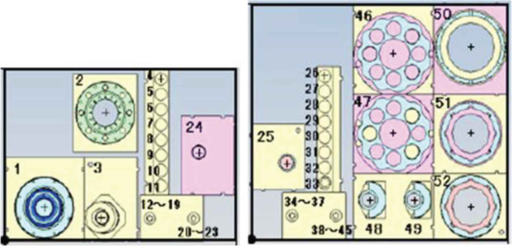
Parts trays.
Next, Tables 2 and 3 show the position data and placeable area data of both robot.
| x (mm) | y (mm) | z (mm) | |
|---|---|---|---|
| Robot | 2210 | 915 | 740 |
Coordinates of double arm robot
| Unit | x1 (mm) | y1 (mm) | z1 (mm) | x2 (mm) | y2 (mm) | z2 (mm) |
|---|---|---|---|---|---|---|
| Left tray | 1811.5 | 1760 | 740 | 1918.5 | 1804.5 | 740 |
| Right tray | 2522 | 1806.5 | 740 | 2628 | 1807.5 | 740 |
| Left parallel hand | 1280 | 1480 | 629 | 2320 | 1480 | 629 |
| Left three claw hand | 1280 | 1480 | 629 | 2320 | 1480 | 629 |
| Right parallel hand | 2100 | 1480 | 629 | 3140 | 1480 | 629 |
| Right four claw hand | 2100 | 1480 | 629 | 3140 | 1480 | 629 |
| Jig A | 3034 | 83 | 740 | 3656 | 1117 | 740 |
| Jig B | 3034 | 83 | 740 | 3656 | 1117 | 740 |
Placement area of each unit
5. SIMULATION RESULTS
Simulations were carried out ten times in each of the three systems. The results of the simulations are described below.
- •
Minimum cycle time:
The smallest work time in each simulation.
- •
Average cycle time:
Average work time of simulation for ten times.
- •
Average simulation time:
Average time taken for ten simulations.
Figure 7 shows the output drawing of the unit arrangement with the highest efficiency. Table 4 shows the best position of units.

Best layout of a double arm robot.
| Unit | x1 (mm) | y1 (mm) | z1 (mm) |
|---|---|---|---|
| Left tray | 1915 | 1775 | 740 |
| Right tray | 2527 | 1807 | 740 |
| Left parallel hand | 2055 | 1480 | 629 |
| Left three claw hand | 2205 | 1480 | 629 |
| Right parallel hand | 2365 | 1480 | 629 |
| Right four claw hand | 2565 | 1480 | 629 |
| Jig A | 3379 | 708 | 740 |
| Jig B | 3039 | 1115 | 740 |
Best position of unit
Table 5 shows both the simulation and the average times.
| A double arm robot | A single arm robot | |
|---|---|---|
| One time | 237.253 | 291.591 |
| Two times | 237.274 | 291.602 |
| Three times | 237.265 | 291.585 |
| Four times | 237.265 | 291.595 |
| Five times | 237.252 | 291.595 |
| Six times | 237.251 | 291.586 |
| Seven times | 237.267 | 291.590 |
| Eight times | 237.300 | 291.593 |
| Nine times | 237.256 | 291.590 |
| Ten times | 237.251 | 291.586 |
| Average times | 237.257 | 291.585 |
Both robot simulation times
6. TESTING
The average difference of the average work time of ten times obtained by each robot was tested. In the alternative hypothesis, the difference between the average value of the working time of the double arm robot was tested and the average difference was tested. In both cases, the null hypothesis was rejected and the alternative hypothesis results that there was a difference in the working time of two robots.
7. CONCLUSION
The layout decision system developed in the research is the system to improve design and production efficiency by automating the unit arrangement determinations of a cell type assembly machine by GA. The system compares the production efficiency of a single and a double arm robot and determines which robot is suitable for assembly.
Comparing the working time of a double and a single arm robot, it was found that a double arm robot is more efficient in this assembly job. It is better to use a double arm robot because of its work efficiency.
It is ascertained that the developed system is more useful to use a double arm robot with this equipment.
AUTHORS INTRODUCTION
Dr. Hidehiko Yamamoto
 He received his B.S., M.A. and PhD from Nagoya Institute of Technology. After 13 years of developing production lines for automotive parts at Toyota Industrial Corporation, he moved to Wakayama University in 1991 and Gifu University in 2000. He is currently a Professor in Department of Mechanical Engineering. His fields of interest are production systems, intelligent systems, knowledge learning and cyber physical factory. He is the fellow of the Japan Society of Mechanical Engineer.
Mr. Takahiro Watanabe
 He received his B.S. in Mechanical Enginering and M.S. in Intelligent Mechanichal Engineering from Gifu University. He joined Mitsubishi Automotive Engineering Co., Ltd. in 2020.
Dr. Takayoshi Yamada
 He received his BE, ME, and PhD in Mechanical Engineering from Nagoya Institute of Technology in 1991, 1993 and 1995. He is a Professor in Department of Mechanical Engineering at Gifu University. He joined Nagoya Institute of Technology as a Research Associate of Mechanical Engineering in 1995. He moved to Gifu University as Associate Professor in 2008. His research interests include grasping, manipulations, sensing and automation systems. He is the member of IEEE, IEEE, the Japan Society of Mechanical Engineers, the Robotics Society of Japan, the Society of Instrument and Control Engineers and the Japan Society for Precision Engineering.
Cite this article
TY  - JOUR
AU  - Hidehiko Yamamoto
AU  - Takahiro Watanabe
AU  - Takayoshi Yamada
PY  - 2020
DA  - 2020/06/02
TI  - Selection System of Robot Type for Cell Assembly Production (Production Efficiency Comparison of Single and Double Arm Robot)
JO  - Journal of Robotics, Networking and Artificial Life
SP  - 77
EP  - 80
VL  - 7
IS  - 2
SN  - 2352-6386
UR  - https://doi.org/10.2991/jrnal.k.200528.001
DO  - 10.2991/jrnal.k.200528.001
ID  - Yamamoto2020
ER  -