
Geometric Measurement Based on the Single Image with a Rectangular Structure
- DOI
- 10.2991/jrnal.k.200909.014How to use a DOI?
- Keywords
- Measurement; single image with rectangular structure; vanishing points; homography
- Abstract
Image-based geometric measurement is getting more attention in machine vision field due to its contact-less and low-cost characteristics. Here the measurement of single image with the rectangular structure is studied, in which only one side length of the rectangle is known, and the coordinates of points in the measured plane are obtained. The intrinsic parameters of the camera are calibrated firstly by using the three vanishing points of mutually orthogonal directions. Then the homography between the image plane and the model plane which the rectangle structure belongs to is derived, and the plane measurement method of the latter is described in details. Furthermore, the measurement experiment is done with the single image taken by the camera, and the validity of the proposed method is verified by comparing with real data.
- Copyright
- © 2020 The Authors. Published by Atlantis Press B.V.
- Open Access
- This is an open access article distributed under the CC BY-NC 4.0 license (http://creativecommons.org/licenses/by-nc/4.0/).
1. INTRODUCTION
As characterized by its non-contact and universality, real-time and repeatability, image measuring gradually becomes one of the important methods for geometric measurement. In binocular measurement systems, precise matching between two images and camera calibration have always been classic problems in photogrammetry. Geometric measurement based on a single image is getting more attention in photogrammetry owing to the avoidance of such problems.
Considering what camera model is appropriate, blade angle measurements of variable stator vanes in jet engines were made based on a single image [1]. It was proved to achieve plane metric rectification based a single view of multiple coplanar circles [2], but the camera’s intrinsic parameters are known. The research was evaluated to verify the utility of a single image approach for scene of crime dimensional analysis [3].
Compared with theses above methods, we propose a new plane measurement method based a single image. The method avoids camera calibration by specialized equipment and only requires that the image scene contains parallel lines in three mutually orthogonal direction, where the length of one side of spatial rectangle is known. The measurement task is completed in accordance with steps in Sections 2 and 3.
2. USING VANISHING POINTS FOR CAMERA CALIBRATION
The vanishing point is useful information for the measurement method based on a single image. It can be used to estimate intrinsic parameters and extrinsic parameters of the camera [4,5], and assist in measuring the height of target on the reference plane [6]. The accuracy of vanishing point detection directly affects the accuracy of measurement result. Currently, there are various methods for automatic vanishing point detection. Owing to inevitable interferences in some special scenes, these methods tend to be misjudged. In order to avoid such possible measurement errors, the method in this paper determines the parallel lines corresponding to three mutually orthogonal directions manually and estimates the vanishing point by using Least Squares.
As shown in Figure 1, Px, Py, Pz are vanishing points corresponding to three mutually orthogonal directions. The parallel lines that determine the vanishing points are respectively parallel to OX, OY and OZ coordinate axis in the spatial coordinate system O-XYZ. C is the orthocenter of ∆PxPyPz, and D is the perpendicular foot on the side PxPy.
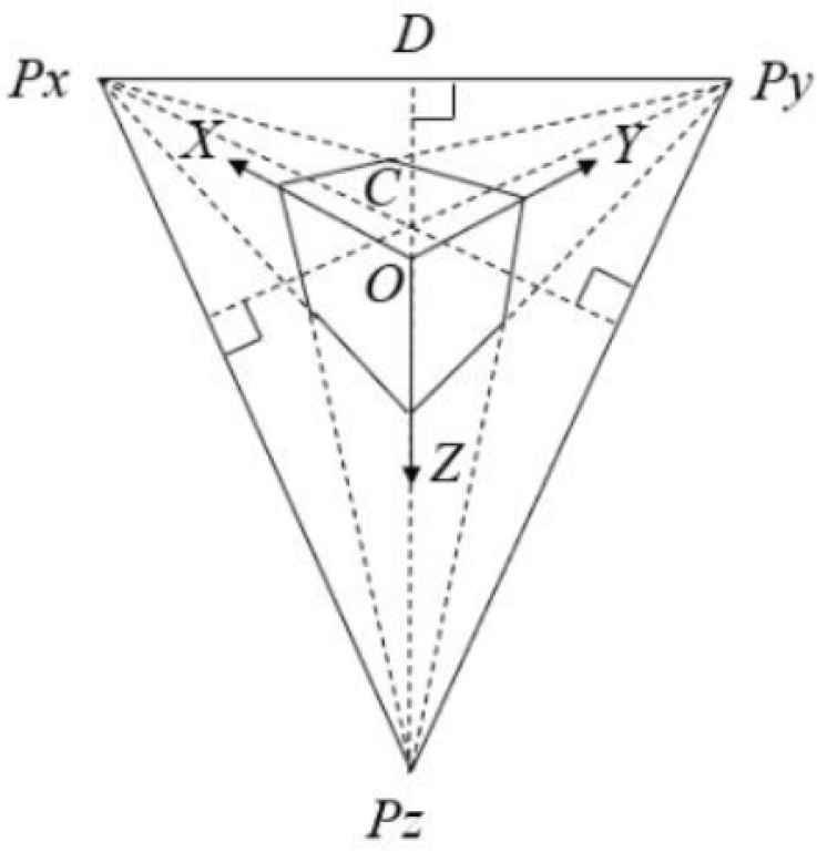
Vanishing points in three mutually orthogonal directions.
There are such basic properties which are very useful for the purpose of camera calibration [4,6].
PROPERTY 1. Point C is the intersection of the optical axis and the image plane.
PROPERTY 2. The focal length of the camera satisfies the following formula.
Afterward the camera intrinsic matrix K is determined. On the image plane, u is the coordinate of principal point along the X-axis and v is the coordinate of principal point along the Y-axis.
Let us consider a typical indoor scene with plenty of information about line segments as shown in Figure 2. Coordinates of vanishing points corresponding to three mutually orthogonal directions on the image plane are estimated based on the above properties.
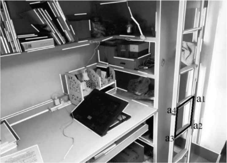
Typical indoor scene with plenty of information about line segments.
Px = (1303.41, –2.06), Py = (593.14, 2014.20), Pz = (–294.08, 101.98). It is assumed that the distortion coefficient equals 0 and aspect ratio equals 0 and then the camera intrinsic matrix is calculated.
3. ESTIMATING THE HOMOGRAPHY BASED VERTEXES OF THE RECTANGLE
It is necessary to specify a spatial rectangle mapping with arbitrary quadrilateral in the image as a reference and the known length of one side of the rectangle serves as the input of the measurement system. We choose the spatial rectangle A1A2A3A4 corresponding to quadrilateral a1a2a3a4 on the image plane as the reference. Spatial points are represented by uppercase letters and subscripted numbers, and points on the image plane are represented by lowercase letters and subscripted numbers.
In Figure 3, the coordinate system O-XYZ is the camera coordinate system and the coordinate system O′-X′Y′Z′ is the world coordinate system. If camera intrinsic parameters are known, the ratio of one side to the other adjacent side in the spatial rectangle is a function of camera intrinsic parameters and the coordinates of vertexes of quadrilateral a1a2a3a4 on the image plane [7].
Notation: xi represents the vector
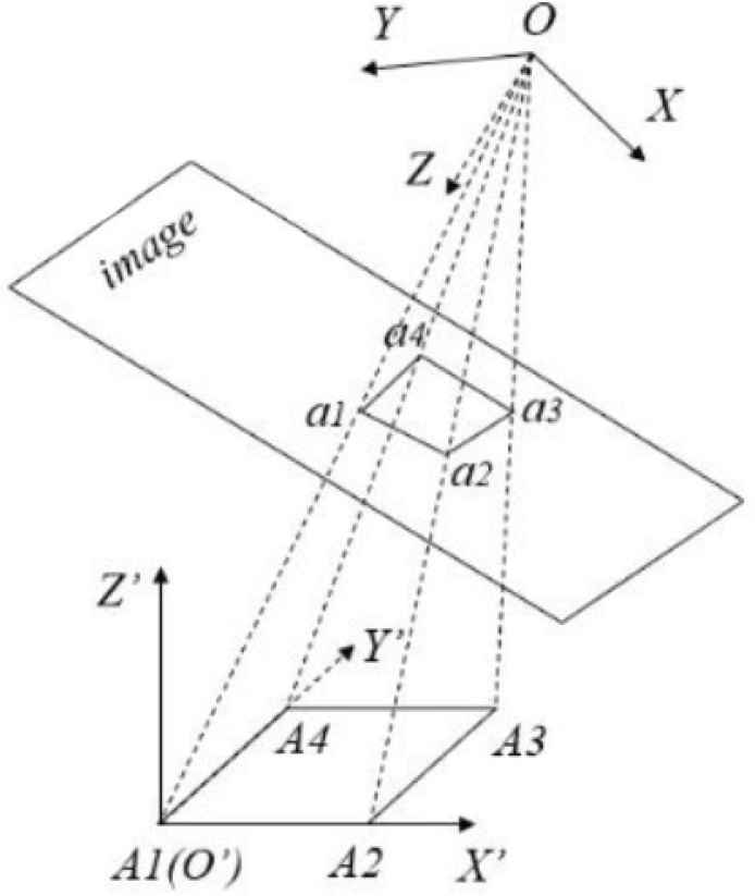
Perspective projection schematic of spatial rectangle A1A2A3A4.
The length of A1A2 and A2A3 are respectively a and b mm based the above algorithm. In the world coordinate system O′-X′Y′Z′, the coordinates of A1, A2, A3, A4 are (0, 0, 0), (a, 0, 0), (a, b, 0), (0, b, 0). The coordinates of a1, a2, a3, a4 correspond to (x1, y1), (x2, y2), (x3, y3), (x4, y4) on the image plane.
Only the homogeneous solution for estimating the homography matrix H is described [8]. Each image-to-world point correspondence provides two equations which are linear in the elements of the matrix H. They are:
The homography matrix H has eight degrees of freedom [9]. For four correspondences, we obtain a system of eight equations in eight unknows and then an exact solution about H is obtained. For the reference rectangle A1A2A3A4, eight equations from its vertexes can be rewritten as a matrix equation Ah = 0.
A performs singular value decomposition and then A = UDVT. h equals the last column of the matrix VT. Afterward h can be rewritten as a 3 × 3 matrix and that is H.
4. PERFORMING EXPERIMENTAL MEASUREMENT
As shown in Figure 4, we select three line segments (L1, L2, L3) which all belong to the spatial plane corresponding to quadrilateral a1a2a3a4, and measure the lengths based on the single image. The experimental results are compared with the results using handheld measurement tool.
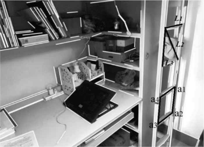
Estimation of length in typical indoor scene.
In terms of the proposed method and handheld measurement tool, we both carried out three replicates of the measurement experiment which are recorded as 1, 2, and 3 to avoid random error. Table 1 is sorted out after the experimental results are recorded accurately. Li (i = 1, 2, 3) represents the result based on the single image and L′i (i = 1, 2, 3) represents the result using handheld measurement tool. From Table 1, the relative measurement error does not exceed 8%. Taking the measurement principle into account, the error seems to be caused by the following two aspects:
- •
Vanishing point detection involves two steps of selecting parallel lines manually and solving overdetermined linear equations by using Least Squares when using vanishing points for camera calibration.
- •
There is no doubt that extracting the coordinates of pixels causes the error. In the first case, the error of estimating the homography matrix occurs if the mouse chooses the adjacent pixels rather than the pixels corresponding to vertexes of the reference rectangle. In other case, selecting the coordinates of pixel wrongly is certain to cause the error when trying to measure based on the single image.
| L1 | L′1 | L2 | L′2 | L3 | L′3 | |
|---|---|---|---|---|---|---|
| 1 | 247.7 | 253.0 | 341.3 | 364.0 | 246.4 | 264.1 |
| 2 | 254.5 | 252.3 | 350.9 | 367.1 | 242.3 | 263.0 |
| 3 | 245.9 | 251.8 | 359.0 | 365.2 | 242.5 | 263.4 |
Experimental results (mm) and results (mm) using handheld measurement tool
5. CONCLUSION
In this paper, we have developed a new method to make plane measurement based on a single image with the rectangular structure. The method requires that the image scene contains parallel lines in three mutually orthogonal direction, where the length of one side of spatial rectangle is known. The measurement is performed on the model plane which the rectangle structure belongs to.
The procedure consists of using vanishing points for camera calibration, estimating the homography based vertexes of rectangle and making the plane measurement. Both the proposed method and direct method using handheld measurement tool have been applied to three replicates of the measurement experiment in a typical indoor scene and good results are obtained. The proposed method gains acceptable accuracy. In the future, optimization of measurement error will be an important issue when the proposed method is used in variable scenes.
CONFLICTS OF INTEREST
The authors declare they have no conflicts of interest.
ACKNOWLEDGMENT
The paper is supported by the project (M18GY300021).
AUTHORS INTRODUCTION
Dr. Jiwu Wang
 He is an Associate Professor, Beijing Jiaotong University. His research interest is Intelligent Robot, Machine Vision, and Image Processing.
Mr. Bo Dai
 He is a postgraduate in Beijing Jiaotong University. His research interest is geometric measurement based images.
REFERENCES
Cite this article
TY  - JOUR
AU  - Jiwu Wang
AU  - Bo Dai
PY  - 2020
DA  - 2020/09/15
TI  - Geometric Measurement Based on the Single Image with a Rectangular Structure
JO  - Journal of Robotics, Networking and Artificial Life
SP  - 208
EP  - 211
VL  - 7
IS  - 3
SN  - 2352-6386
UR  - https://doi.org/10.2991/jrnal.k.200909.014
DO  - 10.2991/jrnal.k.200909.014
ID  - Wang2020
ER  -