
Software Modeling Technique and its Prototype Tool for Behavior of Multiple Objects Using Extended Place/Transition Nets with Attributed Tokens
- DOI
- 10.2991/jrnal.k.200909.011How to use a DOI?
- Keywords
- Software modeling; behavioral model; place/transition net; VDM
- Abstract
This paper shows Extended Place/transition Net with Attributed Tokens (EPNAT) and a modeling technique using it in order to address the problem of EPN. In software modeling using EPN, objects of which the software consists need to be defined individually as sub-EPN models, even if they have the same behavior. On the other hand, in software modeling using EPNAT, objects that have the same behavior can be integrated into one sub-EPNAT model, and therefore EPNAT models would be smaller than EPN models. EPNAT models are converted to VDM++ specifications, and allow engineers to refine software specifications, create programs and test cases. A prototype tool has been developed to support the modeling technique.
- Copyright
- © 2020 The Authors. Published by Atlantis Press B.V.
- Open Access
- This is an open access article distributed under the CC BY-NC 4.0 license (http://creativecommons.org/licenses/by-nc/4.0/).
1. INTRODUCTION
Extended Place/transition Net (EPN) [1,2] is a formal modeling language to represent the behavior of software that consists of multiple objects. The objects mean modules, components, or subsystems in this study, and they interact each other to provide expected functionality of the software. EPN enables engineers to construct unambiguous and executable software specifications that can be used for systematic skeleton code and test case generation. However, in software modeling using EPN, objects need to be defined individually even if they have the same behavior, which causes an increase in model size. A large model that includes redundant definitions often leads to additional cost for design, implementation, test, and maintenance, due to its poor readability.
This paper shows a novel language called EPN with Attributed Tokens (EPNAT) and a modeling technique using it in order to address this problem. In EPNAT, objects are expressed as attributed tokens that are classified into types, and also the states and events of objects of the same type are expressed as places and transitions, respectively. Attributed tokens can pass through places and transitions that belong to the same types as theirs. EPNAT models are converted to VDM++ specifications, and allow engineers to refine software specifications, create programs and test cases. We have developed a prototype tool to support the modeling technique, and thus this paper includes a discussion about it.
The rest of this paper is organized as follows. Section 2 shows software modeling using EPN and its problem. In Section 3, we propose EPNAT and a modeling technique using it. Section 4 gives the overview of our prototype tool. In Section 5, we discuss the effectiveness of the proposed technique and prototype tool, and then show our future work.
2. RELATED WORK
2.1. Software Modeling Using EPN
Petri net including PN has been used in traditional software modeling and testing [3–5]. In previous study, we extended the PN by introducing VDM++ [a formal modeling language in vienna development method (VDM)] [6] in order to enhance its representation power, and generate test cases systematically. The extended PN, that is, EPN [1,2] consists of the following four kinds of structural elements.
- •
Places to express states of each object.
- •
Transitions to express events of each object.
- •
Tokens to express a current state of each object.
- •
Arcs to specify the flow of tokens between places and transitions.
Details that cannot be represented in PN, such as the actions and pre-conditions (guards) of transitions, are formally written in VDM++.
In an EPN model, a transition becomes fireable, if its pre-condition is satisfied and also all the places that are connected by its incoming arcs contain tokens. When a transition is fired, tokens are moved according to its incoming and outgoing arcs, and also the values of variables that are defined for each object can be changed by its actions. The variables can be referred in pre-conditions.
An EPN model consists of multiple sub-EPN models that represent the behavior of objects, and the sub-EPN models are connected by glue transitions that play an important role to specify the interaction among the objects. In an EPN model, the execution traces of software, that is, test cases are described as the sequences of successive markings (distribution of tokens on places), transitions, and values of variables. An EPN model that gives engineers the overview of the behavior of software can be converted to a VDM++ specification that is used to refine the specification of the software.
2.2. Problem
In software modeling using EPN, objects need to be defined individually as sub-EPN models even if they have the same behavior, which causes an increase in model size. In general, a large model that includes redundant definitions often leads to additional cost for design, implementation, test, and maintenance, due to its poor readability.
We introduce an example given in Figure 1 in order to discuss this problem. This Simple Load Balancer (hereinafter, referred to as SLB) contains multiple servers and requests as objects. All server objects have the same behavior, and also all request objects have the same behavior. However, when the behavior of SLB is defined as an EPN model, each object is defined as a sub-EPN model that represents the behavior of each object. That is, if ns and nr are the maximum numbers of servers and requests that can be handled at the same time by SLB, an EPN model of SLB will contain ns and nr sub-EPN models for server and request objects, respectively. There are interaction between the server objects and the request objects. If ng is the number of glue transitions to specify the interaction between one server object and one request object (that is, to connect between two sub-EPN models that represent the behavior of one server object and one request object, respectively), the EPN model of SLB will have ng × ns × nr glue transitions. Additionally, if there are interaction among the server objects and/or among the request objects, a larger number of glue transitions is needed.
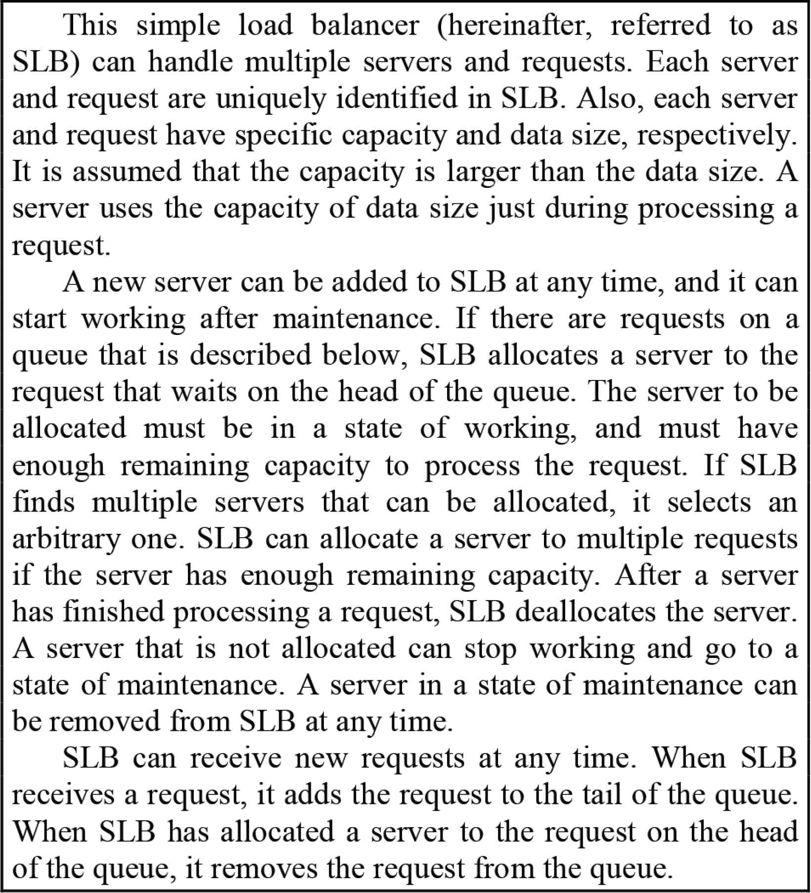
Software requirements of a simple load balancer.
The objects that have the same behavior cannot be easily integrated into one sub-EPN model, since the variables for each object are defined as attributes of an EPN model or each sub-EPN model.
3. EPNAT AND A MODELING TECHNIQUE
In this section, we propose EPNAT and a modeling technique using it in order to address the above-mentioned problem.
3.1. Extended Place/transition Net with Attributed Tokens
Similar to EPN, EPNAT that is the extension of PN consists of places, transitions, tokens, and arcs, and details that cannot be represented in PN are formally written in VDM++. The most obvious difference is that tokens in EPNAT correspond to objects that are classified into types, and they have variables for the objects. In this paper, tokens that have variables for objects are called attributed tokens. For example, in SLB of Figure 1, the server objects (that is, objects of server type) need to have variables such as ID and capacity, and thus attributed tokens of server type (that is, attributed tokens that correspond to the server objects) have those variables. Attributed tokens of the same type have the same variables but different values. For example, the attributed tokens s1 and s2 that correspond to two server objects in SLB have different values, such as s1.ID = 1 and s2.ID = 2, respectively. In this context, “a.v” expresses the variable v of an attributed token a.
Places and transitions that express the states and events of objects respectively are also classified into types, and they are shared by attributed tokens of the same type in EPNAT. Attributed tokens can pass through places and transitions that belong to the same types as theirs. For example, the attributed tokens of sever type can pass through the places and transitions of server type. Note that glue transitions belong to multiple types. Transitions can have actions for attributed tokens. When a transition is fired, the variables of attributed tokens that pass through it can be changed by its actions. Transitions can also have pre- and post-conditions that need to be satisfied just before and after the fire of the transitions, respectively. Places can have invariants, that is, a condition that needs to be always satisfied. The variables of attributed tokens can be referred in pre-conditions, post-conditions, and invariants.
All structural elements of each sub-EPNAT model belong to the same type, and each sub-EPNAT model represents the behavior of all the objects of the type. For example, one sub-EPNAT model of server type covers all the objects (an arbitrary number of the objects) of server type. All sub-EPNAT models are connected by glue transitions in an EPNAT model that represents the behavior of software. In an EPNAT model, the execution traces of software are basically described as the sequences of successive markings and transitions, since the values of variables for each object can be included in the markings.
3.2. Example
Figure 2A shows the overview of an EPNAT model of SLB that is constructed based on Figure 1. It consists of two sub-EPNAT models that represent the behavior of objects of server type and request type. There are two places and six transitions in server type, and two places and three transitions in request type. The transitions “allocate” and “deallocate” are glue transitions, and the two sub-EPNAT models are connected by them.
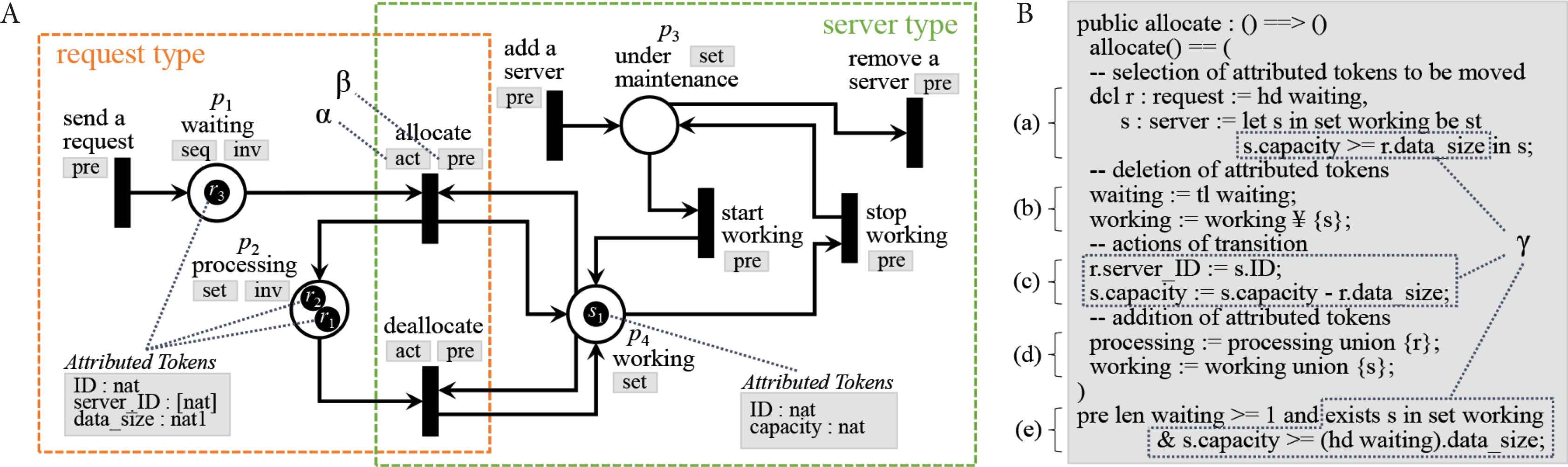
EPNAT model of a simple load balancer. (A) Overview of the EPNAT model. (B) VDM++ codes of the glue transition “allocate”.
The labels “seq” and “set” indicate the collection type of places, that is, whether the order of arrival of attributed tokens on places should be kept or not. Either “seq” or “set” should be specified for each place by engineers. In VDM++ specifications that is discussed later, places with the labels “seq” and “set” are implemented as instance variables of sequence type and set type, respectively. The label “inv” means that a place has an invariant. Details of “inv” are written in VDM++ by engineers, but they are omitted in the overview of an EPNAT model for ease of readability.
The label “act” means that actions are given to a transition. In VDM++ specifications, transitions including their actions, incoming and outgoing arcs are implemented as operations. The labels “pre” and “post” mean that a transition has a pre-condition and post-condition respectively, but the latter does not appear in Figure 2A. Details of the labels “act”, “pre” and “post” are written in VDM++ by engineers, but they are omitted in the overview of an EPNAT model for ease of readability.
Attributed tokens of server type and request type have two and three variables, respectively. The term “nat” means natural number type in VDM++. In Figure 2A, there are four attributed tokens that are labeled “s1”, “r1”, “r2”, and “r3”, respectively. Note that it is a snapshot, that is, a state of SLB under execution at a certain point in time, and there should be no attributed tokens in the initial state of SLB. In VDM++ specifications, attributed tokens are implemented as record type.
The snapshot can be expressed as a marking. When the places are labeled “p1”, “p2”, “p3”, and “p4”, and contain attributed tokens as shown in Figure 2A, its marking is expressed as (p1, p2, p3, p4) = ([r3], {r1, r2}, {}, {s1}). Note that square brackets are used for p1, since its collection type is “seq”.
Figure 2B shows VDM++ codes of the glue transition “allocate”. The statement (a) specifies the way of selection of attributed tokens to be moved. The statements (b) and (d) specify the way of deletion and addition of attributed tokens on the related places, respectively. Note that the Yen sign corresponds to a backslash. The statements (c) specify the actions to be executed on the transition, and they correspond to the label “act” that is pointed by “α ” in Figure 2A. The statement (e) specifies the pre-condition that needs to be satisfied just before the fire of the transition, and it corresponds to the label “pre” that is pointed by “β ” in Figure 2A. In Figure 2B, the codes that are pointed by “γ ” need to be considered and written based on software requirements by engineers, but the others can be generated from Figure 2A.
In this paper, the details of the other structural elements in Figure 2A are omitted because of limitations of space. Many VDM++ codes for them can be generated by our coding pattern that is discussed in Section 3.3.
3.3. Modeling Technique
The modeling technique using EPNAT consists of the following four steps. Note that these steps are not always separated clearly. If engineers find any problems in a current step, they can return to a previous step. Also, engineers can incrementally and iteratively proceed with these steps. The product that has been constructed in each step is executable, and thus should be tested in the end of each step.
Step 1: Construction of sub-PN models
Objects are identified and classified into types, and then the abstracted behavior of an object of each type is defined as a sub-PN model, as shown in Figure 3.
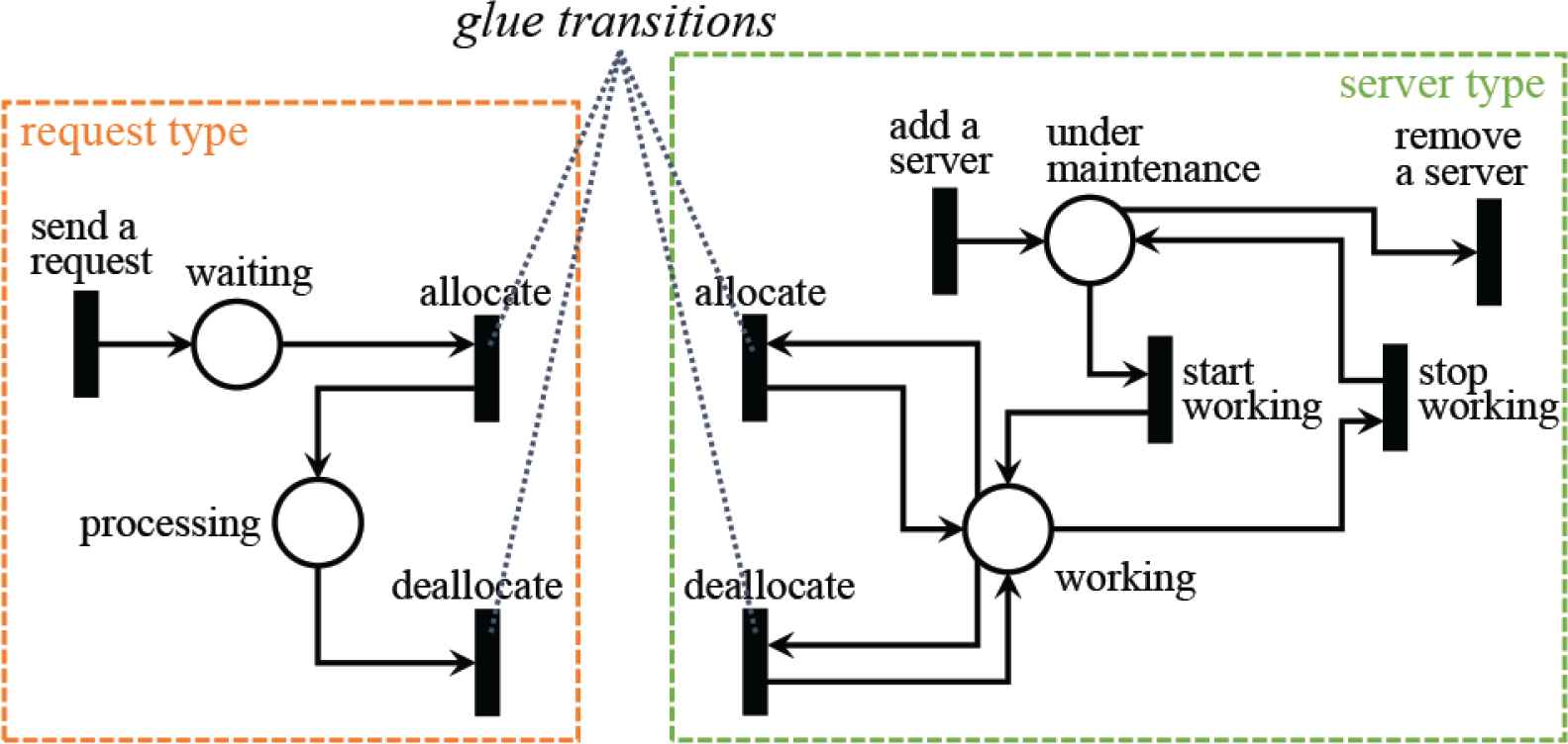
Construction of sub-PN models.
Step 2: Integration of sub-PN models
All the sub-PN models are connected by glue transitions in order to complete a PN model that represents the abstracted behavior of software. Note that there is only one object for each type in the PN model.
Step 3: Addition of details to a PN model
The following definitions, which are written in VDM++, are added to the PN model in order to complete an EPNAT model. The multiplicity of objects on each type is considered in this step.
- •
Variables of attributed tokens.
- •
Collection type of places (“seq” or “set”).
- •
Invariants for places.
- •
Actions to be executed on transitions.
- •
Pre-conditions and post-conditions for transitions.
- •
Conditions to select attributed tokens to be moved on transitions.
Step 4: Conversion to a VDM++ Specification
The EPNAT model is converted to a VDM++ specification. Figure 4 shows our coding pattern to perform this conversion systematically. The codes shown in the form of <terms> mean that actual VDM++ codes are extracted from the EPNAT model, or are written by engineers. Also, “#a - b” means the bth element (such as a variable and a place) of object type #a.
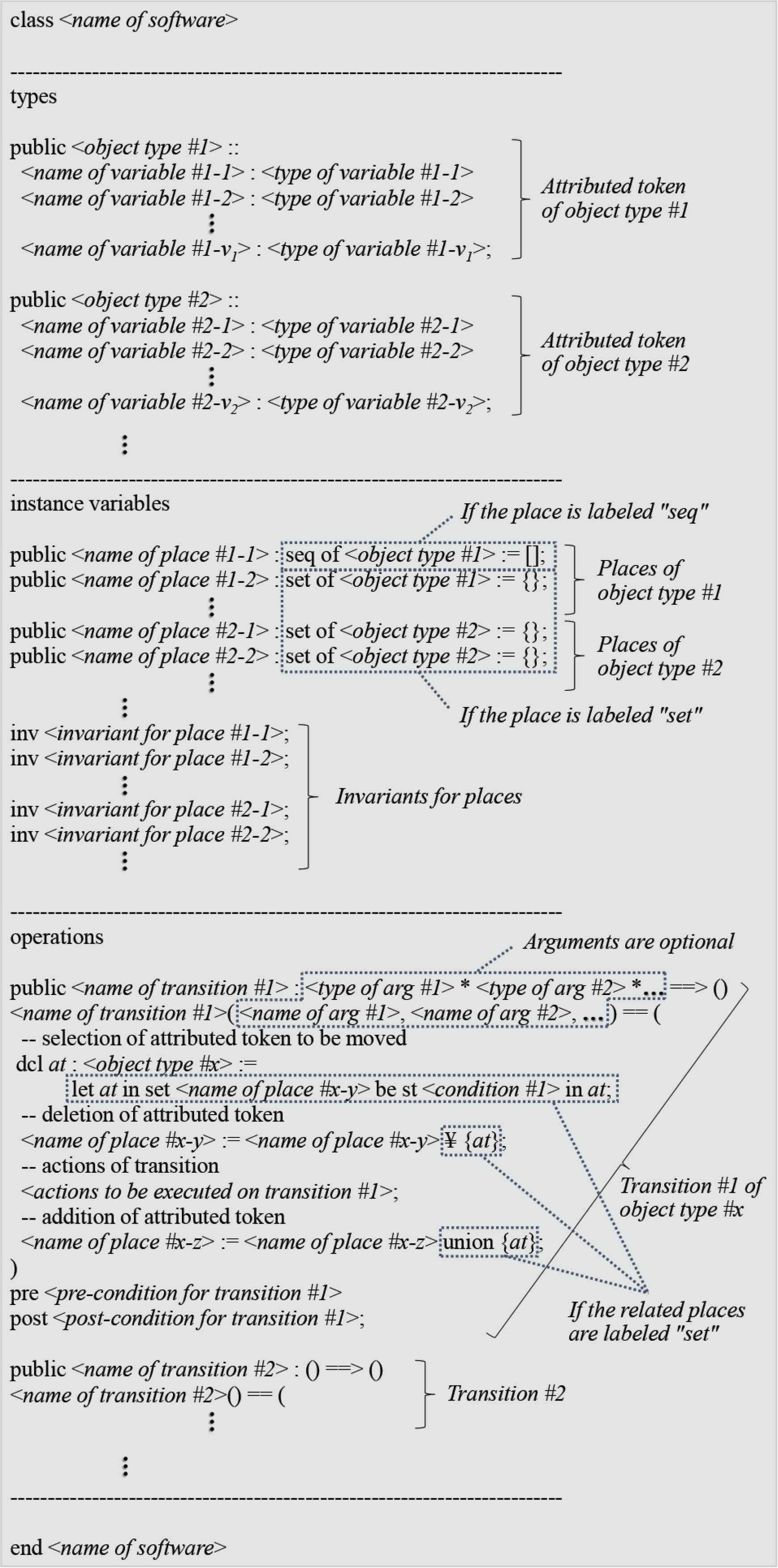
Coding pattern to convert an EPNAT model to a VDM++ specification.
The VDM++ specification is used to refine software specifications, create programs and test cases.
4. PROTOTYPE TOOL
The proposed modeling technique should be supported by a tool, since engineers will need to spend a certain amount of time and effort to construct EPNAT models and VDM++ specifications. Therefore, we have developed a prototype tool in this study. This section shows the overview of our prototype tool that consists of an EPNAT model editor and a VDM++ specification editor.
Figure 5A shows a screen shot of the EPNAT model editor that allows an engineer to construct EPNAT models. Its GUI consists of an overview pane and a detail pane. An engineer can put structural elements of PN on the overview pane, and then can specify their details on the detail pane. The contents of the detail pane are changed based on the kind of structural elements that have been selected on the overview pane. For example, if an engineer has selected a transition on the overview pane, he/she can specify its name, list of argument types, list of argument names, actions, pre-conditions, and post-conditions on the detail pane. If actions, pre-conditions, and post-conditions have been specified for a transition, the labels “act”, “pre”, and “post” appear beside the transition on the overview pane, respectively.
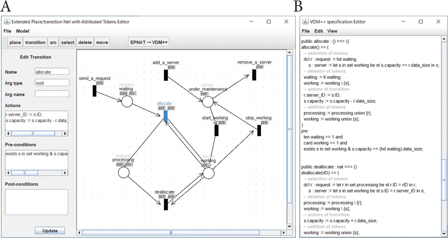
Screen shot of our prototype tool. (A) EPNAT model editor. (B) VDM++ specification editor.
The EPNAT model editor includes a converter based on the coding pattern proposed in the previous section. Therefore, when an engineer has finished constructing an EPNAT model, he/she can automatically convert it to a VDM++ specification. The successfully converted VDM++ specification is sent to the VDM++ specification editor.
Figure 5B shows a screen shot of the VDM++ specification editor. If an EPNAT model has no errors, the VDM++ specification converted from it will be executable on an existing VDM++ interpreter, but can be further developed on the VDM++ specification editor by an engineer.
5. DISCUSSION AND FUTURE WORK
We have proposed EPNAT and a modeling technique using it in order to address the problem of EPN. In software modeling using EPN, objects need to be defined individually as sub-EPN models even if they are the same type, which causes an increase in model size. On the other hand, in software modeling using EPNAT, the objects of the same type can be integrated into one sub-EPNAT model, and therefore EPNAT models would be smaller than EPN models. We discussed the problem and effectiveness by using an example of SLB.
EPNAT models can be converted to VDM++ specifications by using our coding pattern, and allow engineers to refine software specifications, create programs and test cases. However, the coding pattern will not be suitable for extremely large and complex software requirements, since they are defined as one class in a VDM++ specification. For example, each sub-EPNAT model may be defined as a class in order to address this problem, which will be discussed in our future study.
A prototype tool that consists of an EPNAT model editor and a VDM++ specification editor has been developed to support our modeling technique. It allows an engineer to construct his/her EPNAT models by using GUI, and automatically convert them to VDM++ specifications. If the EPNAT models have no errors, the converted VDM++ specifications will be executable on an existing VDM++ interpreter. It is expected that the prototype tool will be useful to reduce engineer’s effort, but there is still room for improvement. For example, engineers would feel the need for some advanced functions to automatically convert their VDM++ specifications to EPNAT models, to automatically find errors on their EPNAT models, to visualize the execution of their EPNAT models, and to generate test cases systematically. We plan to improve the prototype tool, and apply it to non-trivial software requirements to evaluate the effectiveness of our technique further.
CONFLICTS OF INTEREST
The authors declare they have no conflicts of interest.
ACKNOWLEDGMENT
This work was supported by
AUTHORS INTRODUCTION
Dr. Tomohiko Takagi
 He received the B.S., M.S. and PhD degrees from Kagawa University in 2002, 2004 and 2007, respectively. He became an Assistant Professor in 2008, and a lecturer in 2013 in the Faculty of Engineering at Kagawa University. Since 2018 he has been an Associate Professor in the Faculty of Engineering and Design at Kagawa University. His research interests are in software engineering, particularly software testing.
Mr. Ryo Kurozumi
 He received the B.S. degree from Kagawa University in 2019. He is a Master’s student in the Graduate School of Engineering at Kagawa University. His research interests are in software engineering, particularly software design.
REFERENCES
Cite this article
TY  - JOUR
AU  - Tomohiko Takagi
AU  - Ryo Kurozumi
PY  - 2020
DA  - 2020/09/18
TI  - Software Modeling Technique and its Prototype Tool for Behavior of Multiple Objects Using Extended Place/Transition Nets with Attributed Tokens
JO  - Journal of Robotics, Networking and Artificial Life
SP  - 194
EP  - 198
VL  - 7
IS  - 3
SN  - 2352-6386
UR  - https://doi.org/10.2991/jrnal.k.200909.011
DO  - 10.2991/jrnal.k.200909.011
ID  - Takagi2020
ER  -