
A Viscoelastic Contact Analysis of the Ground Reaction Force Differentiation in Walking and Running Gaits Realized in the Simplified Horse Leg Model Focusing on the Hoof–Ground Interaction
- DOI
- 10.2991/jrnal.k.210713.002How to use a DOI?
- Keywords
- Closed-loop linkage; multibody dynamics; dissipative contact force model; hoof–ground interaction
- Abstract
In the present study, the systematic method for the forward dynamics associated with the ground contact model was introduced to be able to consider the viscoelastic effect when contacting with the ground. In particular, we focused on the hoof-ground interaction in the simplified horse leg model because walking and running gaits are known to be different in trajectories; however, the force analysis still remains as unsolved issues. The computational experiments in Matlab, elastic and inelastic impact with the ground was resolved by using the dissipative contact force model proposed by Lankarani and Nikravesh and the ground reaction force was clearly examined in four different conditions from the combination of walking/running and elastic/inelastic contact. As result, two peaks during the stance phase in the walking condition were realized as well as the human gait and a single peak was newly observed in running with a time gap in elastic and inelastic condition. The proposed method contributes to the establishment of the detail time course analysis of the ground reaction force for animal and human gaits in a consistent manner.
- Copyright
- © 2021 The Authors. Published by Atlantis Press International B.V.
- Open Access
- This is an open access article distributed under the CC BY-NC 4.0 license (http://creativecommons.org/licenses/by-nc/4.0/).
1. INTRODUCTION
In the human gait analysis, three different foot-rocker mechanisms are known as heel rocker, ankle rocker and forefoot rocker, which are generated from pendulum dynamics with three fulcrum points of heel, ankle and toe [1]. In a gait cycle, there are two phases as swing stance phases and particularly in the human gait analysis, the stance phase is decomposed to the initial contact for touching with the ground from the heel, the loading response for shifting of the center of mass from back to front, the mid-stance for lifting the heel up, the terminal stance for transition to the swing phase, and then pre-swing [2]. Such as bipedal gait cycle can be simplified to a mechanical system based on a coupled pendulum as demonstrated by McGeer [3], called a passive dynamic walking robot without any electromechanical actuator to mimic three rockers. In this case, the compliant human leg dynamics has been studied with a series of contact points on the rolling surface [4–6] and with the effective roll-over geometry of leg motion [7–9]. The fact suggests that the utilization of the simple skeleton model provides a large benefit to compensate the limitation of experimental measurements in the gain analysis to realize the actual phenomenon of the ground reaction force, because there are evidences in the walking condition [10,11], such as demonstrated two peaks in the temporal evolution of the ground reaction force during the stance phase, while there is a lack of evidences in other gait patterns. In robotic applications inspired from biological mechanisms, an articulated leg with hoof was inspired from the horse [12] and a linkage mechanism to mimic the horse leg trajectory by Batbaatar and Wagatsuma [13] and similar approaches were found in closed-loop linkage mechanisms [14,15]. In the animal locomotion, there are various gait patterns known as walk, trot, gallop and so on [16]. Therefore, the establishment of the detail analytical method for the ground reaction force is highly important to elucidate the principle to differ gaits in the sense of the energy consumption. Focusing on the ground contact phenomenon, the hoof part of the horse leg mechanism can be modelled in the form of the triangle structure to connect three representative points as the toe, heel and ankle, which reproduces the rocker mechanisms. If it is possible to provide kinematic/kinetics of the hoof-ground contact, the viscoelastic effect is also considerable to analyze how much the leg absorbs the impact force when touching with the ground. It realizes the detail analysis of the amount of the energy storage discussed in the distal leg movement and landing motions [17,18]. The purpose of the present study is to establish the basement analytical method for the ground reaction forces in gaits and demonstrate the efficacy of the method in the simplified leg model to focus on the hoof-ground interaction. This paper is divided into following sections. Section 2 introduces the general Multibody Dynamics (MBD) formulation applied to the proposed leg mechanism as well as the viscoelastic contact force introduced to simulate realistic hoof-ground contact. Section 3 contains the kinematic and kinetic analysis focusing on the hoof–ground interaction, while Section 4 summarizes the main results and discusses the potential improvements and limitation of the study.
2. MATERIALS AND METHODS
2.1. Multibody System Formulation for Horse Leg Mechanism
The initial proposal of horse leg mechanism was introduced in the article by Batbaatar and Wagatsuma [13] and its kinematics/dynamics formulated with MBD. Mathematical interpretation and initial state for horse leg mechanism can be written by generalized coordinates q as
The vector of q contains 42 (= 14 × 3) elements which are 14 rigid links and their center of position xi, yi and orientation ϕi are obtained in the present analysis. A set of kinematic algebraic constraint equation can be written as
At the starting point of the numerical simulation, forward dynamics analysis requires the initial state of the target mechanism in order to proceed numerical simulation in next time step.
2.2. Contact Analysis Procedure in Planar Mechanical System Subject to the Impact
When describing the contact impact event between the hoof and ground, we need to determine the state of the contact and accurately acquire the relative deformation and speed at the instant of contact.
In Figure 1, non-contact scenario and representation of viscoelastic ground contact model with variable damping if contact occurs in the system were shown in the kinematic model. When the leg contacts with the ground, the deformation or penetration is estimated as
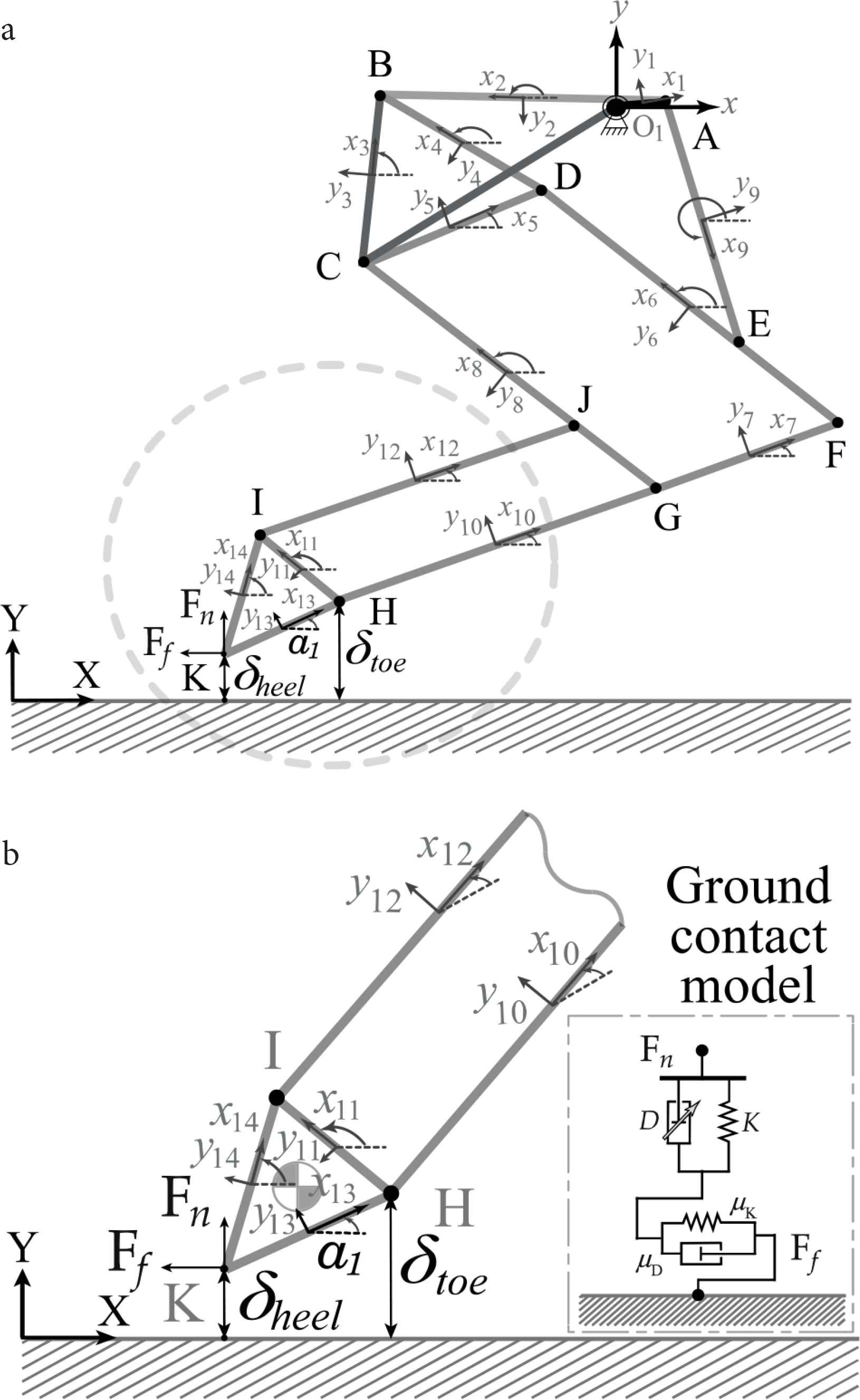
Representations of foot–ground interactions by kinematic model of hoof–ground contact. (a) The whole model to generate trajectories. (b) The focused mechanics.
In Equation (11), the positive value of δ is that distance represent a separation, while negative values denote relative penetration of the contacting bodies. Therefore, the sign of penetration indicates the phase transition from swing to stance and vice versa for the case of hoof–ground contact. By using Equation (10), it is clear to discriminate walking phases and contact forces as continuous function of deformation. Based on updated position and velocity of potential contact points on the hoof K = [Kx, Ky] or H = [Hx, Hy] from the multibody kinematic analysis, relative normal and tangential velocity among the contact points are estimated as
Numerical solution of equation of motion as well as contact force estimation based on state variables can be treated in one computational loop with the iterative computational procedure as shown in Figure 2.
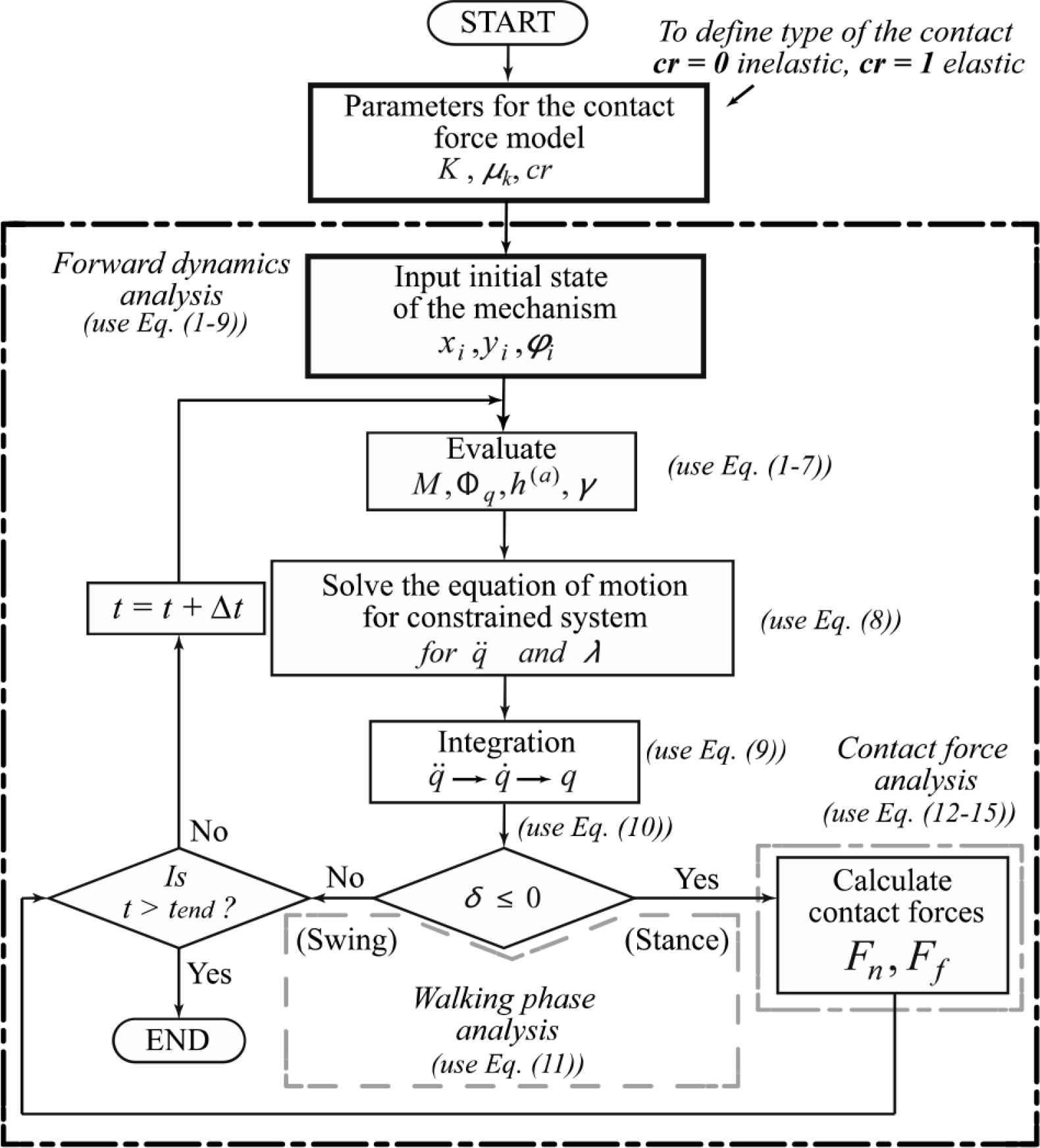
Flowchart of iterative procedure for computational experiment.
3. RESULTS
According to the MBD formulation above, the constitutive contact force model is calculated numerically with kinematic and dynamic analyses, which allow to visualize temporal evolutions of the locomotive trajectory, resultant ground reaction force of the leg mechanism.
Table 1 displays the parameters used in the numerical simulation for contact force analyses of horse leg mechanisms. Matlab-based numerical simulation was performed with a combination of the Euler method with the time step of 1 × 10⁻³ s. For the contact analysis to prevent an unnatural rise of ground reaction force, the stiffness is no smaller than 2 × 10⁴ N/m for the contacting bodies is considered according to simulation in Ristow [24]. It is simply that the ground deformation is equivalent to the resultant motion of the stiffness-damping system under the compression. Two trajectories were selected as typical trajectories to reproduce walking and running gaits according to the mechanics of the simple model, which are generated by changing the control parameters associated with driver constraint in the horse leg mechanism. The trajectories shown in Figure 3, the 1st trajectory considered to be a walking in term of duty factor and step length, evaluation was done in recent study by Batbaatar and Wagatsuma [25]. The 2nd trajectory which has longer step length compared to the 1st trajectory considered to be running gait in which leg orientation controlled by swinging motion with respect to the body, which may potentially generate the propulsive ground reaction force due the intrinsic high rate of angular oscillation at the hoof. In the temporal evaluation of the hoof angle as shown in Figure 4, walking and running gaits were generated in accordance with the first and second trajectories in Figure 3. In the waling gait, the transition of sub-phases commonly occurred in the rolling motion of the triangle structure in both cases. In the walking gait, those sub-phases from heel-strike, flat and toe-off were gradually generated (Figure 4a top), which is consistent with the gradual change of the hoof angle (Figure 4b top), while in the running gait, the transition started from the toe-strike that causes the roll-over sub-phase quickly and then reached to the toe-off sub-phase with a large gap from the ground rather than that in the walking gait.
| Kinematic/Dynamic analysis | ||
| Gravitational acceleration (m/s2) | g | 9.81 |
| The velocity of the driving crank (rad/s) | ω | 2π |
| Total simulation time (s) | t | 0 ≤ t ≤ 1 |
| Baumgarte parameter | α | 15 |
| Baumgarte parameter | β | |
| Time step (s) | dt | 1.0 × 10⁻³ |
| Contact force analysis | ||
| Stiffness (N/m) | K | 2 × 10⁴ |
| Coefficient of restitution | cr | 0 ≤ cr ≤ 1 |
| Coefficient of kinetic friction | μk | 0.4 |
Parameters used in the numerical simulation
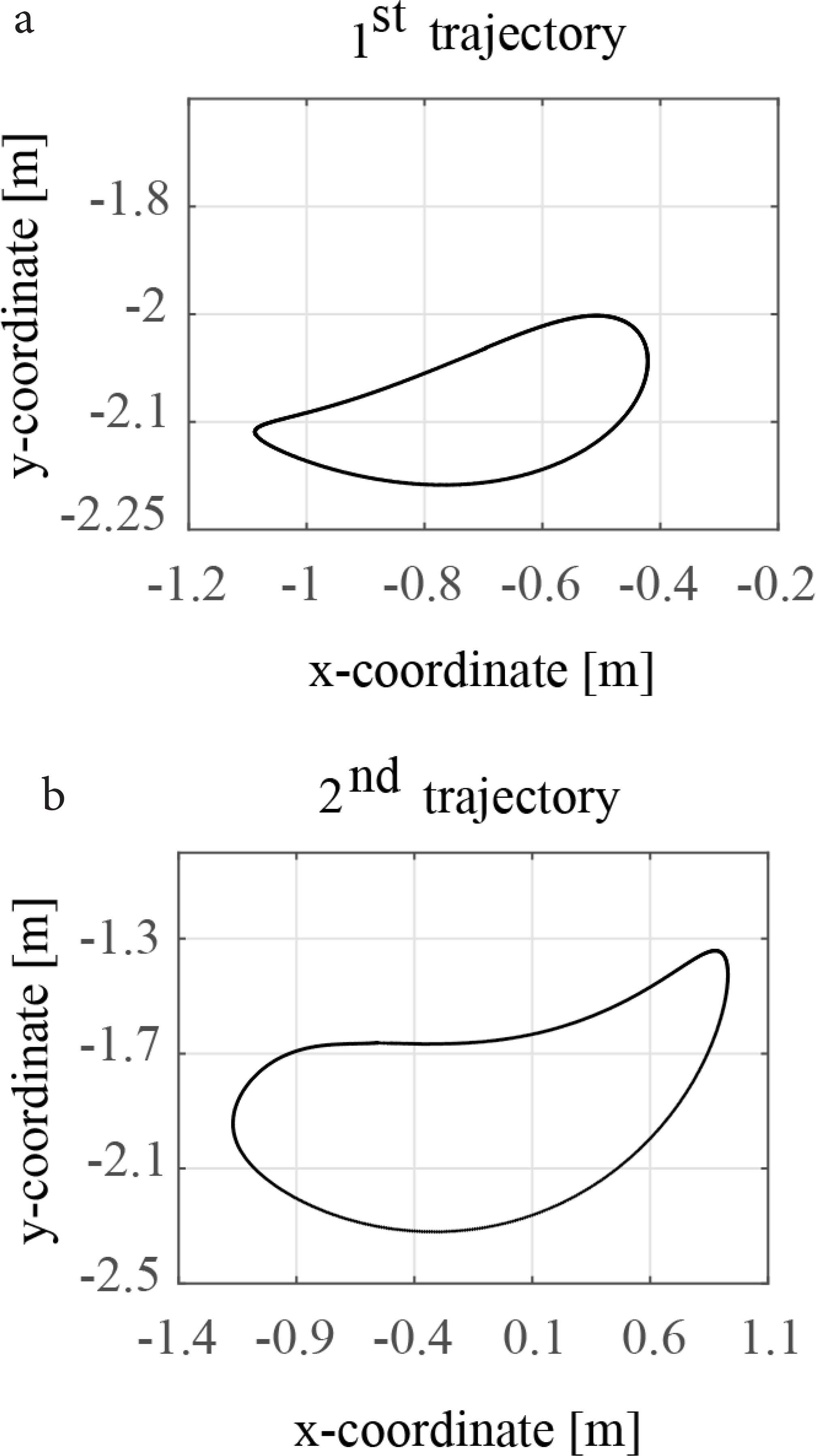
Gait trajectories generated from the horse leg motion. Walking (a), running (b).
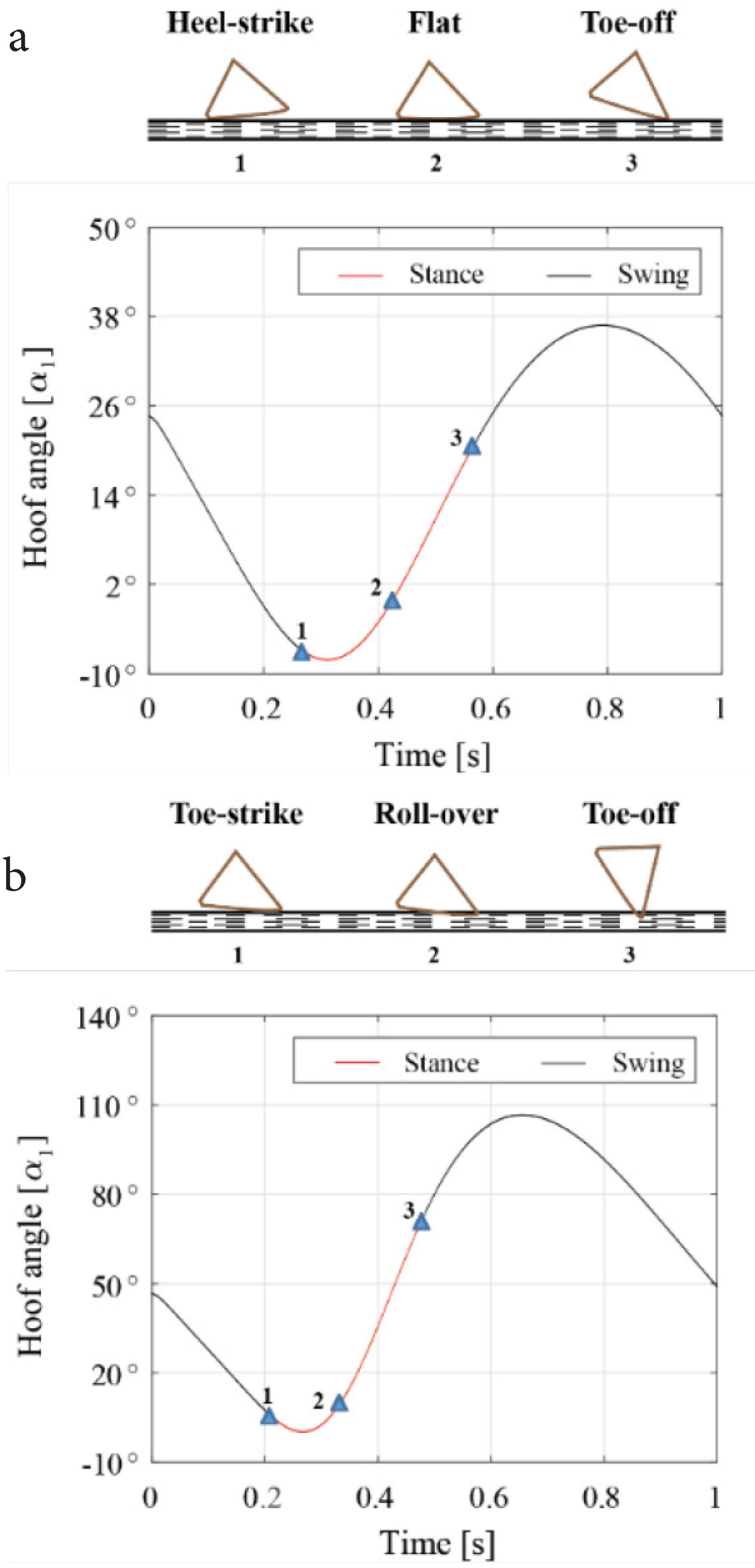
Hoof angle variations with respect to the locomotive trajectory. Angular rotation of hoof in one locomotive cycle of walking gait (a) and running gait (b).
The result was numerically examined as the first contact occurs at instant time t1 = 0.267 s and α1 = −6.83° leaves the ground at t3 = 0.569 s and α1 = −20.9° for the 1st (walking) trajectory. In the case, the hoof rolling over the ground and during the mid-stance multiple contact points were examined at α1 = −0.23° in which hoof was almost parallel with the ground. When the hoof leaves the ground, angular variation during the contact phase was reached 26°. For the 2nd (running) trajectory, the contact phenomenon occurred at the instant time t1 = 0.208 s and α1 = 6.20° firstly, shifted to leaving from the ground at t3 = 0.478 s and α1 = 71.08°. Finally, the hoof angle was reached 64.8°, which is approximately 2.5 times larger than the result in the walking gait. Interestingly, the hoof–ground interaction was significantly influenced by the initial impact phenomenon, which differentiate the grounding part either heel or toe and it reflects to successive sub-phases too. Even in the simple model, the differentiation was clearly observed not only in the trajectory level as a posture and kinematic analysis but also in the kinetic level as the dynamics analysis, which is easily extended to the energy analysis. All these sub-phases are characterized as representative sub-phase to reconstruct the target gait and it can provide the parametric analysis with stiffness and damping, which is associated with an actual parameter from soft tissues in the distal limb. It is because that the compliant contact force model was theoretically described as shown in the method section, which allow to change those parameters related to reaction forces easily.
In the Matlab-based numerical simulation, ground reaction forces were evaluated by using Lankarani and Nikravesh [20] model by changing restitution coefficients as cr = 1 for elastic and cr = 0 for inelastic contact cases. According to the analysis, the maximum contact force was obtained as 453.65 N for the 1st (walking) trajectory in the inelastic contact condition and 175.34 N in the elastic case. Average normal force was 80.83 and 34.88 N respectively. For the 2nd (running) trajectory, the maximum GRF was 8.694 kN for the inelastic contact condition and 5.719 kN in the elastic case. Average normal force was 978 and 800 N respectively. Result showed that the significant reduction of ground reaction force with respect to the viscoelastic contact was estimated as 61.35% in 1st trajectory and 34.22% in 2nd trajectory. In the walking trajectory, multiple point support occurring in which hoof loaded the body weight at mid-stance as shown in Figure 5a, the maximum pressure or force peak indicated in only when the leg first impact and leaves the ground which was consistent with the force pattern observed in the human walking gait [26,27].
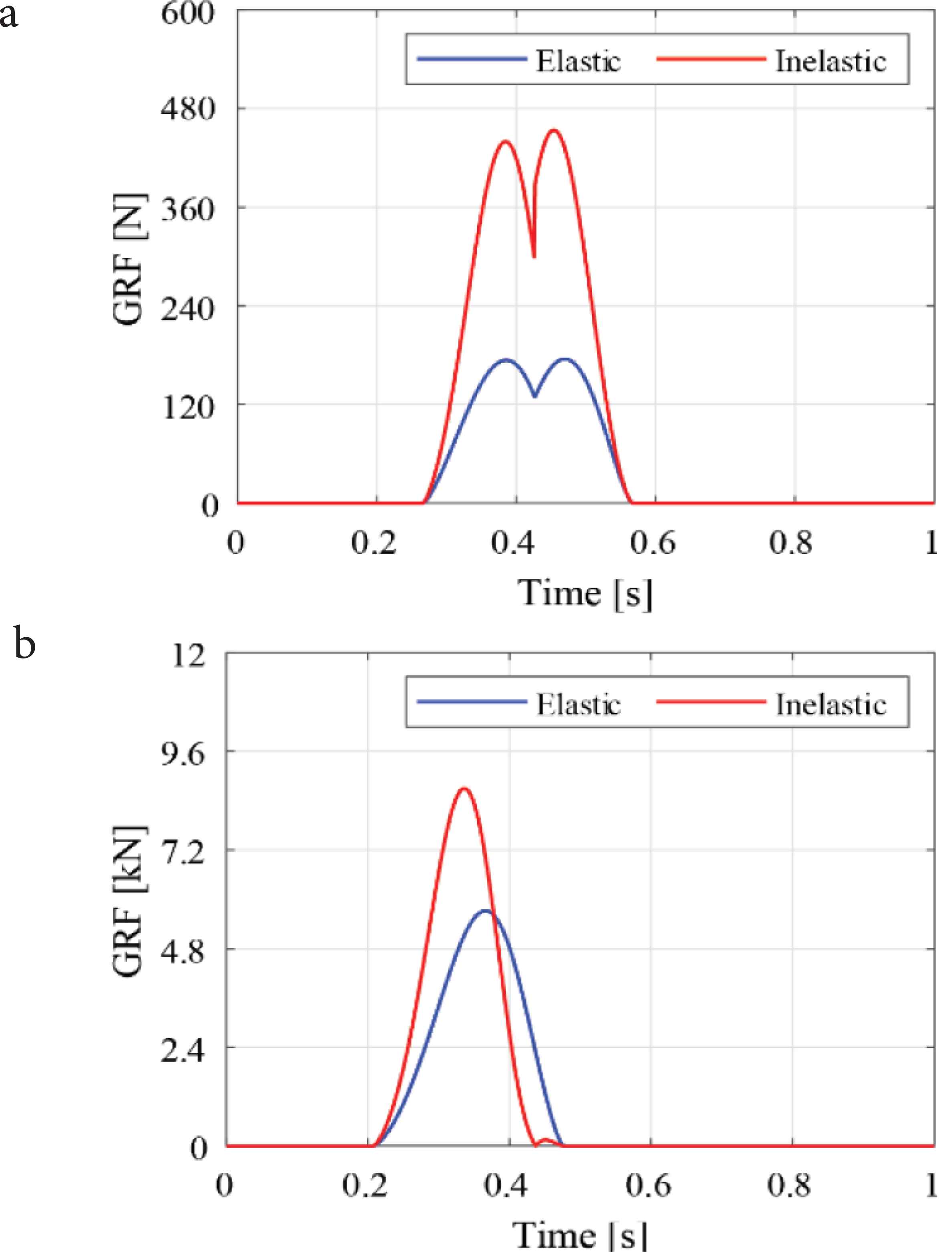
Resultant values of ground reaction forces under the different contact condition. Force pattern of walking gait (a) and running gait (b).
The GRF vector by arrow in Figure 6 represents magnitude, direction of resultant ground reaction force through the entire stance phase in temporal evaluation of Figure 3 for walking and running trajectory. It simply shows that braking force in walking trajectory because in during stance phase ground reaction force was directed to the against moving direction. On the other hand, slight rotation of force vector respect to the gait cycle in stance phase in running gait which indicates the propulsive directional force acting toward center of pressure of moving leg. However, it should be noted that in our simulation leg mechanism was fixed in sagittal plane, therefore detail analysis of force direction could be estimated precisely when multiple leg considered to regenerate the different locomotive gaits [28].
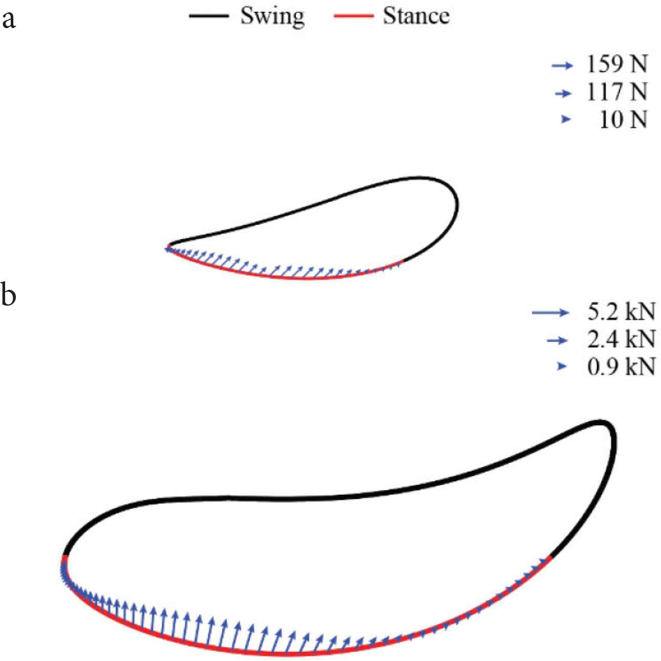
The direction of ground reaction forces in walking (a) and running (b) for the case of elastic contact.
4. CONCLUSION AND DISCUSSION
For the sake of the establishment of the generalized analysis of the viscoelastic effect with respect to various gait patterns, we introduced a novel theoretical method as the integrative framework of the MBD and contact force model and then the computational analysis clearly demonstrated results in four different conditions from the combination of walking/running and elastic/inelastic contact. In the simplification of the hoof mechanism by using a triangle structure to focus on three nodes as heel, ankle and toe, the result revealed not only the two peak generation in the temporal evolution of the ground reaction force during the stance phase of the walking gait, but also a single peak observation in the case of the running gait. The phenomenon was generated from that wheel-like rolling motion of the hoof support and stabilizes the body in mid-stance, and partially consistent with the observation in the human foot–ground interaction [1,10]. In spite of the existence of the complexity in the horse leg structure, our computational result suggested a possible way to analyze the spring-damper effect embedded in principle to the biological mechanism for absorbing the ground reaction force flexibly as a common tendency of the walking and running gaits. The analysis with damping factor model by Lankarani and Nikravesh [20] realized the fact that a soft grounding effectively reduces the ground reaction force. In the actual phenomenon due to the interaction in the musculoskeletal systems such as a vibration from the sensory feedback loop [29,30], the further detail modeling is crucial. Phenomenologically in the level of the force generation, we successfully observed a time delay in a peak in the force time profile specifically in running gaits, which indicates an intrinsic behavior due to the damping factor is highly important in the kicking motion of the hoof. The phenomenon is also need to be verified with more detail leg models and evidences from the biological system [31,32]. Further considerations are possible to compare in the energy consumption due to the elasticity [18] and robotic application [33]. Geometric characteristics of the hoof is of interest to researchers studying on the biological nature mechanical in the hoof shape and its influence in joint angles and contact timing [9,34].
CONFLICTS OF INTEREST
The authors declare they have no conflicts of interest.
ACKNOWLEDGMENTS
This work was supported in part by Mongolia-Japan higher Engineering Education Development (MJEED-JICA) through the joint research project “Development of industrial, service and intelligent systems based on advanced technologies” (J23A16), JSPS KAKENHI (16H01616, 17H06383) and the New Energy and Industrial Technology Development Organization (NEDO), and Project on Regional Revitalization Through Advanced Robotics (Kyushu Institute of Technology/Kitakyushu city, Japan).
AUTHORS INTRODUCTION
Mr. Dondogjamts Batbaatar
 He received his B. Eng. degree in mechanical engineering from Mongolian University of Science and Technology (MUST), Mongolia, in 2013, the M. Eng. degree in the field of mechatronics from MUST. Currently, he is a PhD degree candidate in Graduate School of Life Science and Systems Engineering in Kyushu Institute of Technology, Japan. His research interests include mechanism design, computational non-linear dynamics, and mechatronics.
Dr. Hiroaki Wagatsuma
 He received a M.S. in Mathematical Sciences in 1997 and a Dr. Sci. in Mathematical Sciences in 2005 from Tokyo Denki University. In 2000, he became a Special Postdoctoral Researcher at RIKEN for studying computational models focusing on the brain oscillation. From 2003 to 2008, he was a Research Scientist in the Laboratory for Dynamics of Emergent Intelligence at the RIKEN Brain Science Institute. His research background started from theoretical modeling of brain oscillations, the memory integration process of experienced episodes, and the implementation of oscillatory neural networks into neurorobotics. He is currently an Associate Professor of Kyushu Institute of Technology (KYUTECH) in the department of Brain Science and Engineering, Graduate School of Life Science and Systems Engineering. His research interests have been extended to include Bio-medical Signal Processing and Sparse Coding, Sport Dynamics and Synergy analysis, Brain-Inspired Robotics and Neuroinformatics Institute of Technology, Japan.
REFERENCES
Cite this article
TY  - JOUR
AU  - Dondogjamts Batbaatar
AU  - Hiroaki Wagatsuma
PY  - 2021
DA  - 2021/07/21
TI  - A Viscoelastic Contact Analysis of the Ground Reaction Force Differentiation in Walking and Running Gaits Realized in the Simplified Horse Leg Model Focusing on the Hoof–Ground Interaction
JO  - Journal of Robotics, Networking and Artificial Life
SP  - 78
EP  - 84
VL  - 8
IS  - 2
SN  - 2352-6386
UR  - https://doi.org/10.2991/jrnal.k.210713.002
DO  - 10.2991/jrnal.k.210713.002
ID  - Batbaatar2021
ER  -