
System Integration and Application of a Networking Production Line for Aerospace Precision Manufacturing
- DOI
- 10.2991/jrnal.k.210713.001How to use a DOI?
- Keywords
- Aerospace precision manufacturing; EtherCAT; SCADA; intelligent production line
- Abstract
In this paper, the networking integration application of an intelligent production line is studied and developed for aerospace precision manufacturing. The technical development of the performance equalization and control for EDM machine is also introduced with the related technologies of the machine network and Ethernet for Control Automation Technology (EtherCAT) network. In addition, the development of intelligent production lines is integrated to improve the system stability and production efficiency of production line systems for aerospace component manufacturing. The key technologies of Cyber-Physical System (CPS) and intelligent networking are also integrated to construct the real-time intelligent system monitoring system [Supervisory Control and Data Acquisition (SCADA)] for data record and management. The key technologies of the drilling process are developed for intelligent diagnosis and drilling holes inspection of related production processes. The integrated robot arm is responsible for the loading and unloading of the material, and the entire production line is connected by the EtherCAT network. The automatic optical inspection is introduced at the rear end of the production line to realize the quality judgment of the finished product. Furthermore, the virtual cloud network and the intelligent factory are achieved with the information collection and intelligent monitoring system.
- Copyright
- © 2021 The Authors. Published by Atlantis Press International B.V.
- Open Access
- This is an open access article distributed under the CC BY-NC 4.0 license (http://creativecommons.org/licenses/by-nc/4.0/).
1. INTRODUCTION
In recent years, as the tendency of the popularity in the global aerospace industry, the number of airline passengers has grown year-by-year. Therefore, there is a strong demand for new civil aircraft development. However, the machine object equipment mostly relied on aerospace manufacturing overseas. Because of the weak confidence level, the domestic aerospace manufacturing industry goes into a declining phase. Therefore, in 2014, the Executive Yuan hopes to introduce the manufacturing line to carry out the aerospace components and then promote the domestic tool machine industry to enter the aerospace processing field. The final goal is to promote domestic machine tools to enter the international aerospace supply chain. In this paper, the intelligent networking system is integrated and developed for production line applications based on the EtherCAT network, including control of the robotic arm.
2. MATERIALS AND METHODS
2.1. EtherCAT
Ethernet for Control Automation Technology (EtherCAT) is an Ethernet-based Fieldbus system, invented by Beckhoff Automation. This technology breaks through the system limitations of other Ethernet solutions in the past and has the characteristics of high availability requirements, flexible topology, high-performance, Distributed Clocks for High-Precision Synchronization, and low-cost [1–3]. The EtherCAT master uses a standard Ethernet port and network configuration information stored in the EtherCAT Network Information (ENI) file. The ENI is created based on EtherCAT slave information files which are provided by the vendors for each device. Slaves are connected via Ethernet, any topology type is possible for EtherCAT networks [4]. EtherCAT architecture is shown in Figure 1.
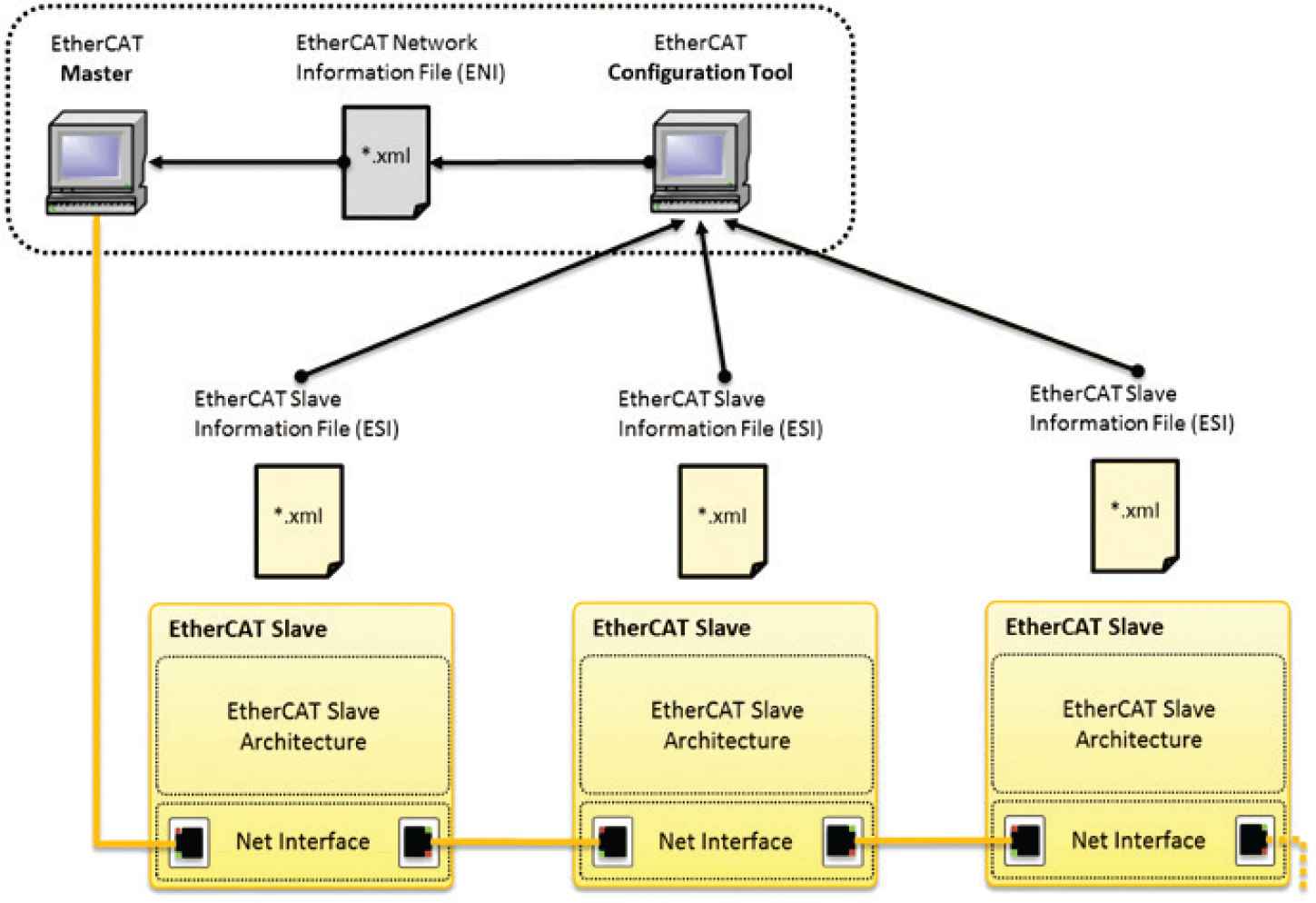
EtherCAT network architecture [4].
2.2. CANopen over EtherCAT
Using the CANopen over EtherCAT (CoE) application layer protocol, EtherCAT communication has the same standard protocol as CANopen, Including the same Object Dictionary (OD), Service Data Object (SDO) settings, Process Data Object (PDO) data transmission, and the objects refer to Controller Area Network (CAN) in Automation (CiA) 402 for motion control. These objects can define the state control of the motor, basic motor parameter settings, and data feedback objects, etc., providing objects that can be used for basic motor control operations [5].
2.3. Control of Robotic Arm
For the robotic arm control, it will bypass its upper controller for PC control. Here, a Six-Axis articulated robot will be used as an example. To control the Six-Axis articulated robot, regard it as six motion control cards for communication connection and control, and use EtherCAT as the communication method of the motion control cards network communication. In the part of physical control, the robot kinematics must be rediscussed, and it is mainly divided into two parts, forward kinematics, and inverse kinematics. Forward kinematics is to substitute the known rotation angle θi of each axis arm into the homogeneous transformation matrix, and then obtain the position of the end controller relative to Cartesian coordinates (xi, yi, zi). On the contrary, inverse kinematics is to know the posture and position (xi, yi, zi) of the arm relative to Cartesian coordinates, and in turn, obtain the required rotation angle θi for each axis joint of the arm and used in the derivation and verification of robot arm control. To get the relative relationship between forward and inverse Kinematic equations, the rotation and translation position relationship between each axis of the Six-Axis articulated robot is expressed by Denavit–Hartenberg parameters, to obtain the simplified four main parameters, as shown in Figure 2 [6–8].
αi−1: Angle between
ai−1: Distance between
θi: Angle between
di: Distance between
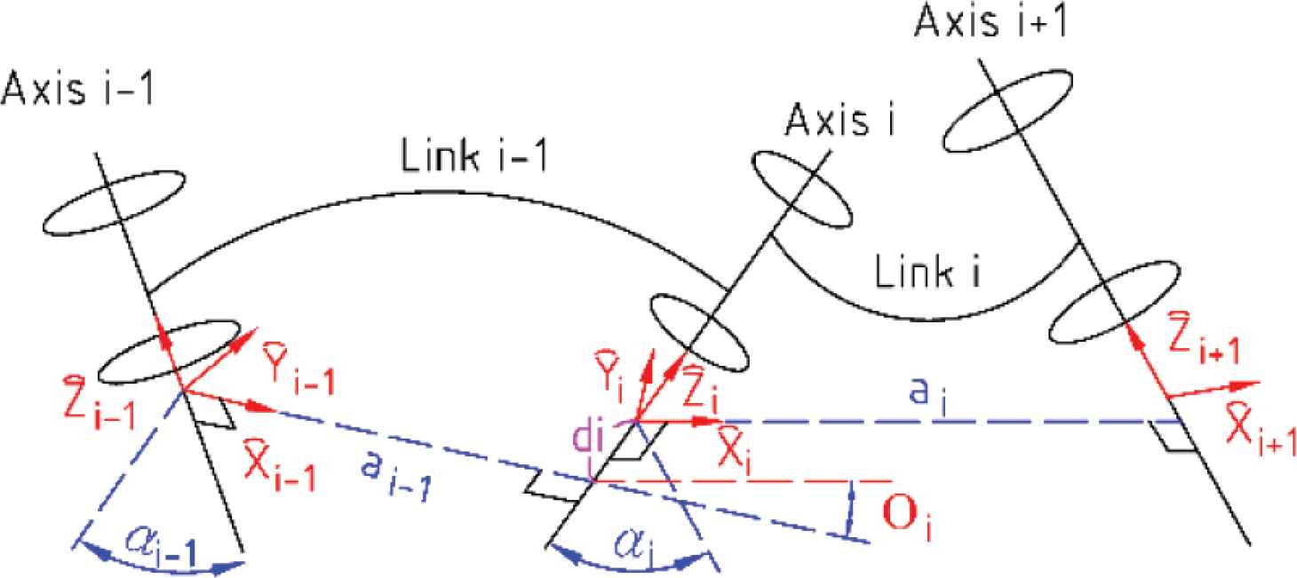
Link coordinate system D–H parameters.
After defining the parameters required for the relative transformation of each axis coordinate system, the relationship between translation and rotation can be obtained through Figure 3, then obtained the DH parameter table, see Table 1. The four parameters defined in the DH parameter table are briefly described below, and their geometric meanings are as follows:
θi: The angle of joint rotation.
di: The translation distance of the joint between the rotation coordinates.
ai: The length of the mechanical link between the two joints.
αi: The rotation angle of the output shaft of the two joints.
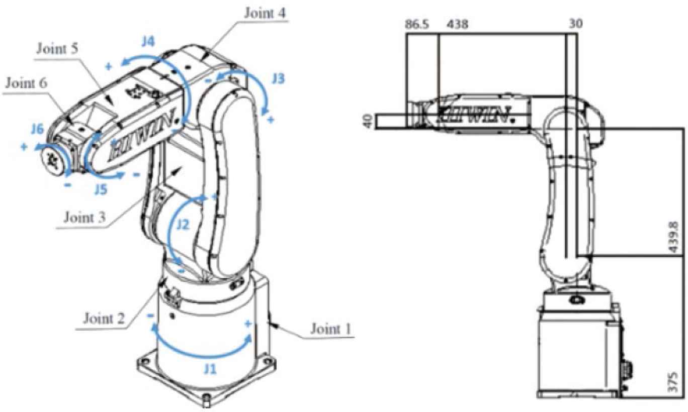
Six-Axis articulated robots and the axis length diagram between each axis [9].
| Joint | θi | di (m) | ai (m) | αi (°) |
|---|---|---|---|---|
| 1 | θ1 | 0 | 0.03 | 90 |
| 2 | θ2 | 0 | 0.4398 | 0 |
| 3 | θ3 | 0 | 0.04 | 90 |
| 4 | θ4 | 0.438 | 0 | −90 |
| 5 | θ5 | 0 | 0 | 90 |
| 6 | θ6 | 0.0865 | 0 | 0 |
Denavit–Hartenberg parameters
The position of the robotic arm endpoint in the coordinate system is derived from the homogeneous transformation matrix. Since the coordinate conversion between the axis of the robotic arm is rotational and translational, by substituting the listed D–H table parameters into Equation (1), the homogeneous transformation matrix between each axis can be established. In Equation (1), the 3 × 3 matrix in the upper left corner is the rotation matrix, the 3 × 1 matrix in the upper right corner of the translation matrix. By finding the conversion relationship between the space points of the two coordinate systems, the transformation matrix between each joint can be calculated. Put it into Equation (2) to find the transformation matrix between the endpoint and the origin.
At this point, the position of the end controller in the forward kinematics Cartesian coordinates (xi, yi, zi) obtained by this transformation matrix can be used as a verification of the position of the control calculation [6–8].
3. SYSTEM DESIGN AND ARCHITECTURE
For the development of an intelligent production line application, the Electric Discharge Machine (EDM) is the core machine and integrates the robotic arm by the EtherCAT network. The Supervisory Control and Data Acquisition (SCADA) system is to connect the EDM, the robotic arm, and the Automated Optical Inspection system (AOI system) through the communication network to establish an aerospace precision manufacturing, as shown in Figure 4.
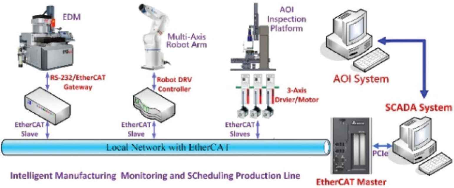
Aerospace precision manufacturing.
4. SYSTEM INTEGRATION AND TESTING
The experimental method of Intelligent Production Line Application is to run the overall electric discharge machining production line after the EtherCAT local area network and the SCADA system have been constructed and connected to monitor. Review the results of drilling at special angles of the workpiece to verify the effectiveness of the EDM production line automation. To add the Six-Axis articulated robot to the overall machining production line network for control, it will bypass its upper controller of the initial factory and connects to the six motion control cards, which are regarded as nodes. To control the Six-Axis articulated robot, use the kinematic calculation method above to calculate the corresponding value of pulse to the rotation angle of each axis required to reach the target position. Then use the CiA402 moving object of the motion control cards itself for EtherCAT transmission, the control object is shown in Figure 5. Then use the value of pulse which is obtained from the feedback object to infer the current angle position information. There are several modes for motion control of the robotic arm, here use interpolated position mode. Also, the control of the electric gripper matched with the robotic arm uses its USB port to communicate and control with the computer via UART.
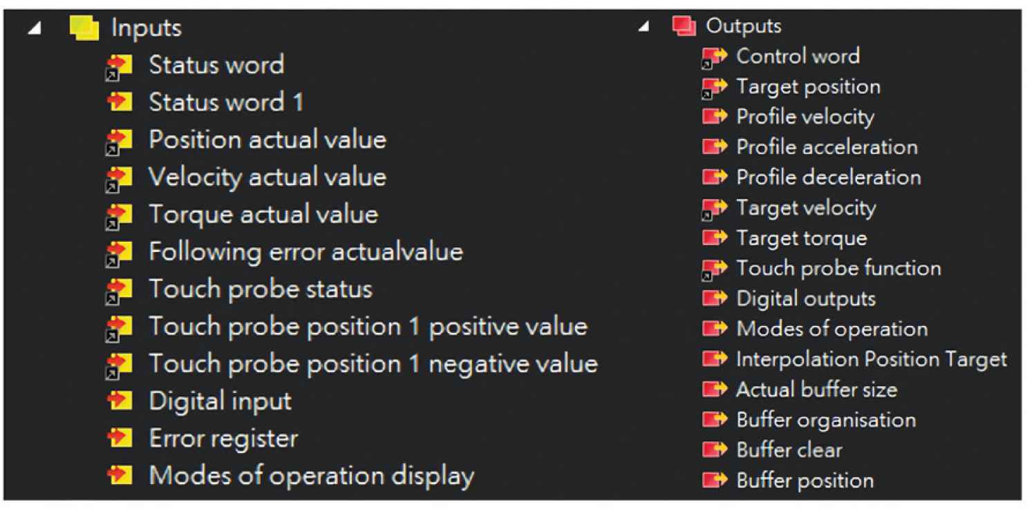
Control object of the robotic arm.
Before the SCADA system starts to connect and control, it is necessary to use TwinCAT to create related corresponding objects and settings through the description of each slave device XML file to construct an EtherCAT network. After the completion of network construction, set the initial parameters of SDO, and set through the objects in the object dictionary, then set the PDO Output object that will be added during subsequent operations. Real-Time numerical control can execute after it into the operational state. Then, SCADA software can be used to connect to the network for reading object information and issue control commands. The SCADA system is to monitors the EtherCAT network status of the entire production line, it is mainly connected to the master station TwinCAT via API. SCADA system can be used to instantly grasp the actions and status of each machine and equipment, and establish a user interface for users to monitor and manage the production line status and to provide the inspection results of the finished workpiece. The SCADA system is shown in Figure 6.
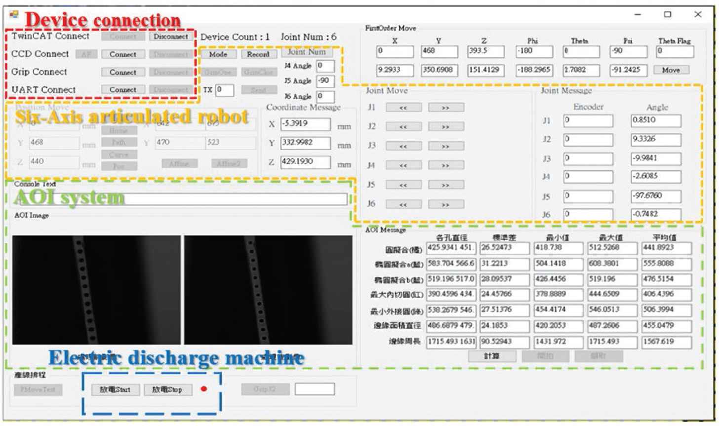
The SCADA system.
According to the function, C# based SCADA system can be divided into four parts, device connection, Six-Axis articulated robot, AOI system, and electric discharge machine. The functions of each part will be introduced below.
4.1. Device Connection
The main function of the device connection is to connect with the EtherCAT Master TwinCAT on the production line and communicate and control transmission with each node through this network. In addition to the EtherCAT network connection, this SCADA system also integrates other hardware connections, such as the USB connection of the AOI automatic positioning system, and the connection control of the electric gripper of the robotic arm. On the network connection, the customized RJ45 interface 100BASE-TX is used as the network physical layer, which is connected to the main station by serial connection with each station, and a personal computer is used as the main station. Other devices are connected to a personal computer using USB Port and then controlled by the SCADA system. The interface of TwinCAT master is shown in Figure 7.
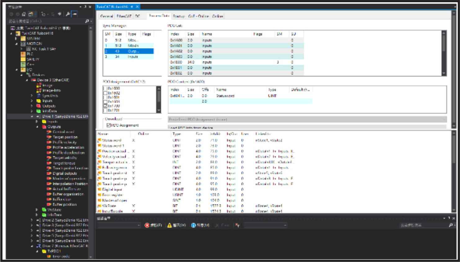
The interface of TwinCAT master.
4.2. Six-Axis Articulated Robot
After connecting its motion control cards via the network and completing the network communication, the robotic arm can be controlled. It operates on the Cartesian coordinate system and coordinated with single-axis angle numerical control of the rear three axes to adjust the detection angle, and calculated by feedback object to know the current position information and feedback information of each axis. Also, a single-axis control is added for the user to find the grasping point to ease the scheduling design.
4.3. AOI System
This AOI system consists of two parts, the automatic positioning system, and the AOI optical inspection. Connect the MCU and AOI system to obtain the current positioning information and display the result of the finished workpiece inspection on the interface. The AOI system of this EDM production line is composed of an industrial camera, a telecentric lens, a ring light source, and an inspection platform. The inspection platform is used as the starting station for the feed of the production line and the placement station for the processing completion, when the processing flow starts, the workpiece to be processed is placed on this platform, after the processing finished, send it back to the platform for the final AOI optical inspection, and perform drilling holes information inspection, acquisition, and analysis on the processed product for quality inspection. The pictures and analysis information are sent to the production line monitoring system for users to use and judge. The analysis information is shown in Figure 8.
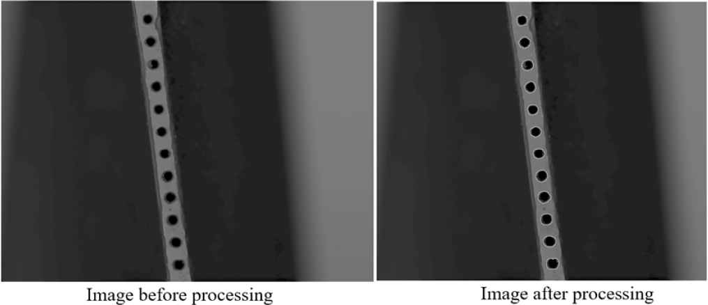
Images inspected by AOI system.
4.4. Electric Discharge Machine
Given the issues related to industrial safety, the EDM manufacturer (Ching Hung Machinery & Electric Industrial Co., Ltd.) does not provide control methods related to EDM computer host and external connection, like an independent working machine. However, to achieve the goal of automation of the production line, an EtherCAT network node must be constructed separately. Through the external relay circuit with the EtherCAT communication control board that transmits the signal to the internal relay of the EDM, then the existing programs in the EDM computer will be activated, the program including executing, signals of fixed-point feedback, and emergency stop. The control interface is as shown in Figure 6, the red light is matched with the feedback signal. While the electric discharge machine is stably ready, the green light will be on, and the processing program can be started with Start at this time. The workpiece being drilled by EDM is as shown in Figure 9.
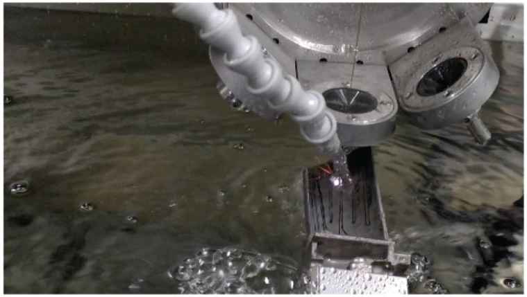
The workpiece being drilled by EDM.
As aerospace consumables workpieces are not available, it can only be machining through similar workpieces, such as galvanized iron blocks, stainless steel plates, aluminum plates, and radiator stator scrap for machining and measurement. During the trial run of the overall electric discharge machining production line, the network controller issues work instructions, the robotic arm carries out the reclaiming operation, and the electric discharge machine is processed. After the machining is completed, the robotic arm sends it to the AOI system for quality inspection. The entire automated production line operates smoothly. The workpieces after machining are shown in Figures 10 and 11 depict the integral EDM production line.
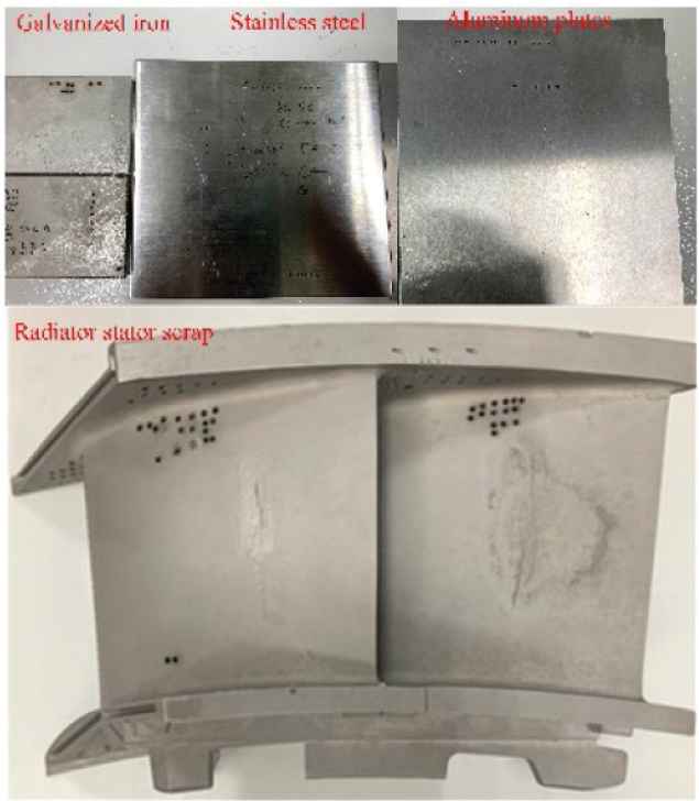
Workpieces after machining.
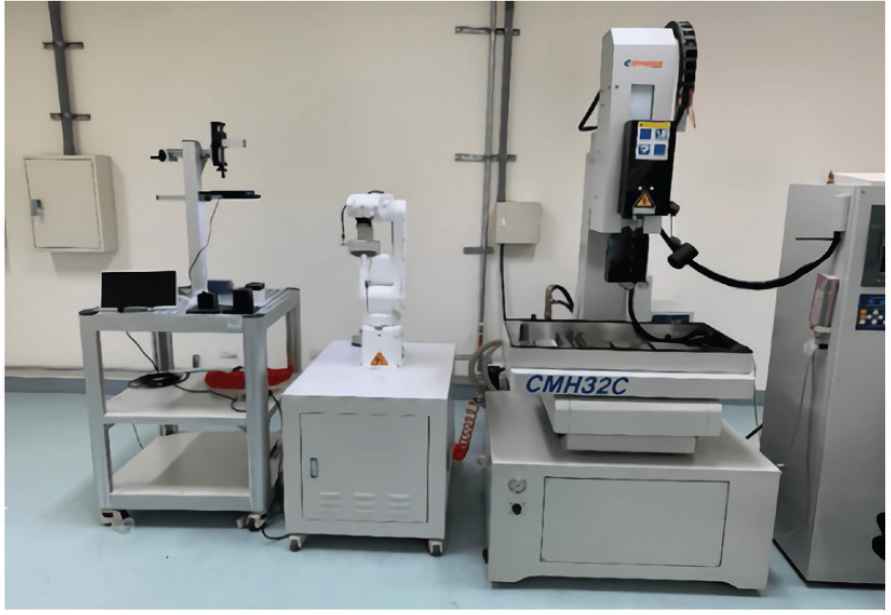
Electric discharge machining production line.
5. CONCLUSION
In this paper, the networking system integration and development is focused on EtherCAT protocol for an intelligent production line application, use the EtherCAT network to integrate the Six-Axis articulated robot and EDM, and design a SCADA system to connect the EDM, Six-Axis articulated robot, and AOI system via the communication network to build an automated network control station. During the trial run of the overall electric discharge machining production line, the network controller issues work instructions, the robotic arm carries out the reclaiming operation, and the EDM is processed. After the machining is completed, the robotic arm sends it to the AOI system for quality inspection. The entire automated production line operates smoothly. On the network control station, the SCADA system can be used to grasp the actions and status of each machine tool and equipment of the production line in real-time, and establish a user interface for users to monitor and manage the production line status, and to provide the inspection results of the finished workpiece. This Networking System Integration and Development of an Intelligent Production Line Application has been completed, which can implement intelligent communication between machine tools and equipment, and achieve the goal of intelligent control of machining equipment, improve machining quality and productivity.
CONFLICTS OF INTEREST
The authors declare they have no conflicts of interest.
ACKNOWLEDGMENTS
This research was supported by the Ministry of Science and Technology, Taiwan, R.O.C. under Grant: MOST 107-2218-E-150-007 and 108-2218-E-150-004.
AUTHORS INTRODUCTION
Chau-Chung Song
 He is with the Department of Aeronautical Engineering, National Formosa University, Taiwan. He received the PhD degree in Electrical and Control Engineering from National Chiao Tung University in 2001 at Taiwan. He is currently a Professor in Institute of Aeronautical and Electronic Technology, and Department of Aeronautical Engineering, National Formosa University since 2006. His research interests include the analysis and control of nonlinear systems, the integration application of networking information system, the UAV technology and applications, and the cloud network and Cyber-Physical system (CPS).
Chun-Chi Wang
 He received his Bachelor’s degree from the Department of Materials and Energy Engineering, MingDao University in 2018. He received the M.S. degree in Graduate Institute of Aeronautical and Electronic Technology from National Formosa University in 2021 at Taiwan. He is currently a PhD course student in National Yunlin University of Science and Technology, Taiwan.
Geng-Yi Lin
 He received his Bachelor’s degree from the Department of Aeronautical Engineering, National Formosa University, Taiwan in 2021. He is currently a Master’s course student in National Formosa University, Taiwan.
Chung-Wen Hung
 He received the PhD degrees in Electrical Engineering from National Taiwan University in 2006. Currently, he is an Associate Professor in National Yunlin University of Science & Technology. His research interests include IoT, IIoT, Power Electronics, Motor Control, and AI Application.
REFERENCES
Cite this article
TY  - JOUR
AU  - Chau-Chung Song
AU  - Chun-Chi Wang
AU  - Geng-Yi Lin
AU  - Chung-Wen Hung
PY  - 2021
DA  - 2021/07/23
TI  - System Integration and Application of a Networking Production Line for Aerospace Precision Manufacturing
JO  - Journal of Robotics, Networking and Artificial Life
SP  - 73
EP  - 77
VL  - 8
IS  - 2
SN  - 2352-6386
UR  - https://doi.org/10.2991/jrnal.k.210713.001
DO  - 10.2991/jrnal.k.210713.001
ID  - Song2021
ER  -