
Experimental Evaluation of a Data-Driven Control System using an Electronic Thermal Regulator
- DOI
- 10.2991/jrnal.2018.5.2.3How to use a DOI?
- Keywords
- PID controller; data-driven controller; electronic thermal regulator; FRIT
- Abstract
IoT (Internet of Things) has been attracted attention, and several system data can be obtained by communication and it is stored in database. The input/output data is expected to be utilized to control systems in industries. The data-driven technique has been proposed as a way to utilize database for calculating PID gains. The scheme is effective for non-linear system control, but it is hard to be implemented to systems. It is due to restricted memory capacity. Therefore, a host computer calculates PID gains based on the data-driven scheme instead of a control device. The calculated gains are sent to a general controller from a computer. The effectiveness of the proposed platform is demonstrated by the experimental examination.
- Copyright
- Copyright © 2018, the Authors. Published by Atlantis Press.
- Open Access
- This is an open access article under the CC BY-NC license (http://creativecommons.org/licences/by-nc/4.0/).
1. Introduction
In recent years, IoT has been received attention, and the data of systems obtained through a lot of sensors is hoped to be utilized to control systems in industries1. Such data, which is collected by a communication between sensors and cloud, is stored in database.
On the other hand, the electronic thermal regulators2, control devise, are employed to control systems, in which PID controller3, 4 is basically applied. In the case of using PID controller, the PID gains must be tuned considering the properties of controlled objects. Most of the practical controlled objects have nonlinearity, and it is hard to control them suitably by using the fixed PID controller. Therefore, the data-driven technique5 having effectiveness for non-linear systems has been proposed. Calculating a set of PID gains based on the database depending on current operating data, the data-driven scheme can appropriately control such systems. The data-driven technique needs the large memory for database. Therefore, it is hard to implement this technique to the electronic thermal regulator due to its restricted memory capacity. If the computer is utilized for implementing the data-driven control scheme, the new interface between the computer and controlled object must be introduced instead of the electronic thermal regulator. Hence, the data-driven scheme is hardly implemented to the industrial field.
In this paper, the construction of the data-driven control platform using the electronic thermal regulator is firstly explained, in which the database is introduced in order to realize the data-driven PID controller. According to the proposed platform, the host computer calculates PID gains by the data-driven technique and sends them to the control device. As a result, the aforementioned memory capacity restriction of the electronic thermal regulator can be avoided. Furthermore, the existing interfaces between electronic thermal regulator and control objects do not need to be changed.
In this paper, section 2 shows the schematic of the data-driven control platform. The design of a data-driven controller is explained in section 3. In section 4, the effectiveness of the proposed platform is verified by implementing it for an actual experimental equipment. The paper ends with concluding remarks in section 5.
2. Construction of the data-driven control platform
The schematic of a data-driven control platform is shown in Fig. 1. In this paper, the electronic thermal regulator plays a role of a controller. The electronic thermal regulator receives control outputs, e.g. temperature, humidity or pressure through a sensor and determines the control input. In the proposed platform, the reference signal and control I/O data are sent to the host computer having a database from the electronic thermal regulator. The host computer sends a set of PID gains calculated on data-driven scheme to the electronic thermal regulator. Since the host computer sends PID gains instead of the control input, the electronic thermal regulator can control systems using last PID gains even if the communication is interrupted.
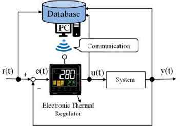
The schematic of a data-driven control platform.
3. Design of the data-driven controller
3.1. Controlled Object
The controlled object can be described by the following nonlinear system:
3.2. Design of a data-driven controller
[STEP1] Generate an initial database: In the data-driven control, the control parameters are calculated from the historical closed-loop data stored in a database. If there are no stored information vectors in the database, the data-driven scheme cannot work. To create initial database, it is required to obtain the closed-loop data. The data stored in the form of the following equation:
[STEP3] Calculate PID gains: The suitable PID gains around the query are calculated by applying the steepest descent method to selected neighbor vectors in STEP 2.
3.3. Off-line learning by FRIT
The fictitious reference iterative tuning (FRIT)6 is a technique calculating directly the control parameters from a pair of I/O data. The new PID gains Knew are obtained by updating the database stored PID gains Kold. The following steepest descent method is applied to modify the PID gains:
In equation (14), the fictitious reference input
4. Experimental control results
In this paper, the data-driven control platform was applied to the temperature equipment shown in Fig. 2. The electronic thermal regulator E5CC-QQ2ASM and the interface converter K3SC-10 for connection between the electronic thermal regulator and a host computer was utilized, which they made by OMRON Corporation. The temperature equipment equips with a ceramic heater and an aluminum block. The control output y(t) is the temperature of the aluminum and is measured with a thermocouple of K-type. The control input u(t) is duty ratio which determines how much to heat through a relay. The reference signal r(t) was set to r(t) = 60 [°C] and the sampling time Ts was set to 2 [s]. After the control output can track to the reference signal, a disturbance was applied that non-heated aluminum contacts and cools the heated one.
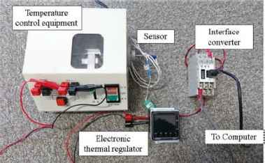
The appearance of the temperature control equipment.
The PID parameters for generating initial database were denoted as follows:
The initial data vectors were stored database according to equation (5). The user-specified parameters for the experiment are shown in Table 1.
| Orders of the information vector | nu = 1 |
| ny = 2 | |
| Number of neighbors | k = 6 |
| Learning rates | ηP = 1.0 × 10⁻³ |
| ηI = 1.0 × 10⁻⁴ | |
| ηD = 1.0 × 10⁻³ | |
| Initial Number of data | N(0) = 1138 |
User-specified parameters for the experiment.
The desired polynomial P(z−1) was designed as

The control results by the proposed platform, and by a fixed PID controller.
5. Conclusion
In this paper, the effectiveness of the data-driven control platform has been verified. In the proposed platform, it is handily permitted advance control law that a host computer sends PID gains to the electronic thermal regulator using an existing interface. Even if PID gains cannot be sent to the electronic thermal regulator, a system is controlled using the last PID gains. In this paper, the PID gains are adjusted at every step. In future work, the control design method, in which PID gains are adjusted only the case where the control performance is deteriorated, will be considered.
References
Cite this article
TY  - JOUR
AU  - Yuka Okubo
AU  - Yoichiro Ashida
AU  - Takuya Kinoshita
AU  - Toru Yamamoto
PY  - 2018
DA  - 2018/09/30
TI  - Experimental Evaluation of a Data-Driven Control System using an Electronic Thermal Regulator
JO  - Journal of Robotics, Networking and Artificial Life
SP  - 89
EP  - 92
VL  - 5
IS  - 2
SN  - 2352-6386
UR  - https://doi.org/10.2991/jrnal.2018.5.2.3
DO  - 10.2991/jrnal.2018.5.2.3
ID  - Okubo2018
ER  -