
Research on SVG Control Method Under Unbalanced Conditions
- DOI
- 10.2991/jrnal.2018.5.2.5How to use a DOI?
- Keywords
- SVG; complex filter; steady-state error; proportional complex integral control;
- Abstract
In order to reduce the complexity of traditional methods, a PCI (Proportional Complex Integral) controller is adopted to control SVG under unbalance-grid condition, which has better performance than PI controller to eliminate steady-state error to compensate nonlinear loads. Based on the αβ frame, the proposed control scheme considerably reduces total algorithm complexity. The current control loop is designed based on mathematical modeling under unbalanced conditions. Simulation and experimental results are provided to validate the correctness of the proposed methods.
- Copyright
- Copyright © 2018, the Authors. Published by Atlantis Press.
- Open Access
- This is an open access article under the CC BY-NC license (http://creativecommons.org/licences/by-nc/4.0/).
1. Introduction
In recent years, the research of SVG (Static Var Generator) is mainly focused on the fast and accurate detection of reactive current component and the simplification of reactive power control methods1,2. Proportional-resonant control method3–4 can make the input current achieve the zero steady state error. However, the method has a high requirement for the accuracy of the equipment parameters, which is difficult to achieve the ideal state. Deadbeat control method and predictive current control method are used in paper5–7. These control methods have some difficulties in the design of precise models, which can easily cause the system to appear unstable.
This paper presents PCI control method based on αβ stationary reference frame. The control method not only effectively eliminates the steady-state error of AC current, but also improves the compensation performance of the equipment.
2. Control Method
The main circuit structure of the voltage-source SVG is shown in Fig. 1. Phase voltage of three-phase power grid is expressed as ea, eb and ec; Three-phase load current is represented by ila, ilb and ilc; The DC side voltage is expressed as udc.
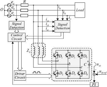
Main circuit topology of SVG
2.1. Positive and negative component separation method based on complex filter
In this paper, a method of separating positive/negative sequence components from the grid current by using the complex filter is proposed. The principle block diagram is shown in Fig. 2. In figure, ωc is the cut-off frequency of the filter.
From Fig. 2,
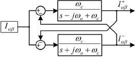
Separation of the positive/negative sequence current
Three-phase current transformed into αβ stationary coordinate system can be written as:
A specific block diagram is shown in Fig. 3.
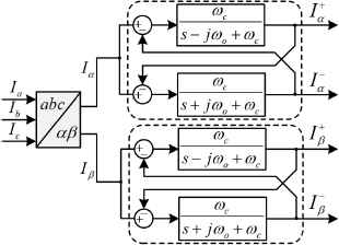
Separation of positive/negative sequence current under three-phase unbalance
2.2. PCI control method
The traditional proportional complex integral control is based on αβ stationary coordinate system as shown in Fig. 4. When the current is controlled in three-phase coordinate system, the control computation is greatly increased due to the coordinate transformation. In this paper, according to the equivalent transformation of variables, proportional complex integral control which can be applied directly in three-phase coordinate system is designed.
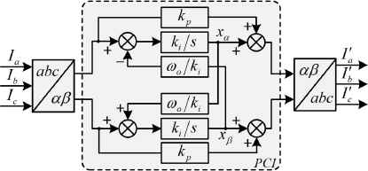
PCI control based on αβ stationary coordinate system
The phase difference of each phase is 120°, which can be given as
The control diagram of three-phase orthogonal frame from (4) is shown in Fig. 5.
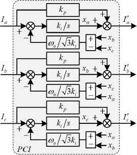
PCI control based on three-phase orthogonal frame
3. Analysis of simulation result
The relevant system parameters are given in Table 1.
| Parameter | Value | Parameter | Value |
|---|---|---|---|
| Grid Line Voltage | 400V | DC side voltage | 700V |
| Grid Frequency | 50Hz | DC bus capacitor | 6μF |
| Grid Reactance | 5mH | The rated Capacity | 200kVar |
System Parameters
In the system, the bandwidth is usually selected to be 10 times higher than the fundamental frequency, and also less than 1/5 of the switching frequency, so the range of bandwidth fb is 500 to 2000. The transfer function of the closed loop of the system is obtained as
When only kp is considered, the closed loop amplitude frequency features can be achieved as
Where fb=650Hz, ωb=4100rad/s, (8) give rises to kp=0.1. Under the requirements of the system bandwidth, the design make fb=690Hz, ωb=4330rad/s, (6) give rises to kp=20. Under unbalanced conditions, the SVG control strategy based on complex filter and PCI control can be shown in Fig. 6.
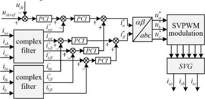
The Model of SVG
According to above model, simulation is carried out in MATLAB/Simulink environment. Fig. 7 shows the load current. Fig. 8 shows tracking error comparison of the output current between PI control and PCI control. When the system is controlled under PCI control after 0.5s, the SVG output current is close to reference current, and the error is controlled to 0.1A. So PCI control has a good effect on steady state error.
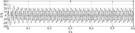
(a) The load current
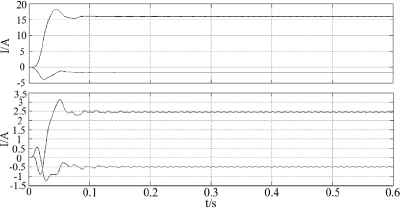
(b) Positive and negative sequence component of load current
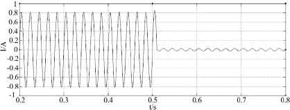
Tracking error comparison of the output current between PI control and PCI control
4. Experimental Verification
In this paper, RT-LAB semi-physical platform is verified to the proposed strategy as shown in Fig. 9. The SVG control circuit is based on the core of DSP28335, and the main part of the circuit is realized by the RTLAB platform. For the system, the phase voltage value of input grid is 311V, the DC side voltage is 700V, and the resistance of pure resistive load is 100 Ω.
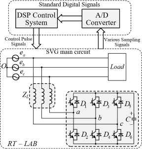
Schematic diagram of system structure
In order to avoid the disturbance caused by the equipment start-up, the equipment is cut off after the normal running time of 1s, and the experimental waveforms of this system are shown in Fig. 10, Fig. 11 and Fig. 12.
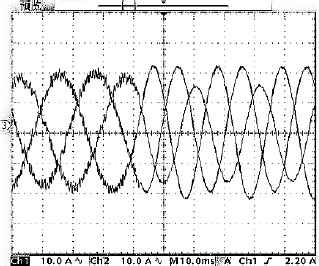
Three-phase current on grid side
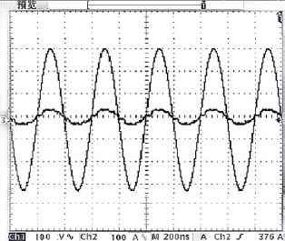
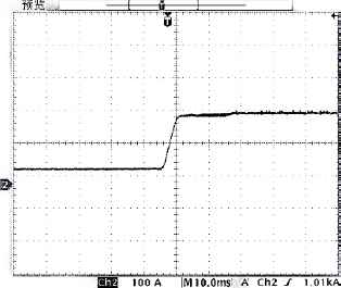
Voltage and current of A grid phase
Three-phase load current unbalance
Fig. 10 shows three-phase current state can be balanced when the device is operating normally; while the device is disconnected, the system state becomes unbalanced. As shown in Fig. 11, after compensating for reactive component and negative component, the voltage of A phase is in accordance with the phase angle of this phasic current, which reveals that the system has better compensation effect. From Fig. 12, it can be seen that unbalance degree is reduced from 0.28 to 0.06 for the three phase current of the load, which achieve the state's demand for unbalance degree.
The experimental results show that the SVG control strategy based on complex filter and PCI control can realize real-time compensation for reactive component and negative component under unbalanced conditions.
5. Conclusion
Under unbalanced condition, the PCI controller is studied using in SVG to compensate nonlinear loads. Compared with traditional control method, the proposed scheme can considerably reduce total algorithm complexity. The current control loop is designed based on the mathematical modeling under unbalanced input conditions, and parameters of PCI controller is designed. An experimental platform is built based on DSP 28335 and RT-Lab. Simulation and experimental results are given to demonstrate the effectiveness of the proposed control scheme.
Acknowledgements
Fund projects: National Natural Science Foundation (U1504518).
References
Cite this article
TY  - JOUR
AU  - Zheng Zheng
AU  - Yousong Zhou
AU  - Guopeng Zhang
PY  - 2018
DA  - 2018/09/30
TI  - Research on SVG Control Method Under Unbalanced Conditions
JO  - Journal of Robotics, Networking and Artificial Life
SP  - 97
EP  - 100
VL  - 5
IS  - 2
SN  - 2352-6386
UR  - https://doi.org/10.2991/jrnal.2018.5.2.5
DO  - 10.2991/jrnal.2018.5.2.5
ID  - Zheng2018
ER  -