
Generation of Cell-Like Images Using Euclidean Distance from Edge
- DOI
- 10.2991/jrnal.k.210521.004How to use a DOI?
- Keywords
- Non-photorealistic rendering; cell; Euclidean distance; edge; clarification; automatic generation
- Abstract
A non-photorealistic rendering method has been proposed to generate cell-like images in which cell-like patterns are represented in photographic images. Cell-like patterns are automatically generated by the change of density of photographic images. However, cell-like patterns are irregularly arranged. In this paper, we propose a method to arrange cell-like patterns along the edges of photographic images. In addition, our method can express cell membrane and cell nucleus in cell-like patterns more clearly than the conventional method. We improves the conventional method by using Euclidean distance from the edges. We show that appealing cell-like images can be generated by our method through experiments using various photographic images.
- Copyright
- © 2021 The Authors. Published by Atlantis Press B.V.
- Open Access
- This is an open access article distributed under the CC BY-NC 4.0 license (http://creativecommons.org/licenses/by-nc/4.0/).
1. INTRODUCTION
Non-photorealistic rendering is a field of computer graphics that can generate effective illustrations and attractive artistic images. Some researchers have proposed non-photorealistic rendering methods to simulate art expression techniques and to develop unprecedented artistic approaches [1–7]. One of the unprecedented artistic approaches is a method to generating cell-like images by an iterative calculation using inverse iris filter from photographic images [8]. Cell-like patterns are composed of cell membrane and cell nucleus. Cell-like images are overlaid with cell-like patterns in photographic images. Cell patterns are automatically generated by the change of density of photographic images. However, cell-like patterns are irregularly arranged. Therefore, a method for aligning cell-like patterns in cell-like images has been proposed [9]. The conventional method [9] is implemented by synthesizing sine and cosine waves into photographic images. However, in the conventional method [9], cell-like patterns are mainly arranged in a grid pattern, and therefore the edge preservation of cell-like images is not high. Also, the actual cells are not arranged in the grid pattern.
In this paper, we propose a method to arrange cell-like patterns along the edges of photographic images. Our method also has the feature that the cell membrane and cell nucleus in cell-like patterns can be expressed more clearly than the conventional methods [8,9]. We improve the conventional method [8] by using Euclidean distance from the edges. Cell-like images of our method can give an impression different from cell-like images of the conventional methods [8,9]. By conducting experiments using various photographic images, it is visually confirmed that cell-like patterns can be generated along the edges and cell-like patterns that express the cell membrane and cell nucleus more clearly than the conventional methods [8,9] are generated. In addition, it is visually confirmed that the size of cell-like patterns can be changed by changing the values of the parameters in our method.
This paper is organized as follows: Section 2 describes our method to arrange cell-like patterns along the edges, Section 3 shows experimental results and reveals the effectiveness of our method, and the conclusion of this paper is given in Section 4.
2. OUR METHOD
Our method is implemented in two steps. In the first step, distance-transformed images are created by calculating Euclidean distance from the edges of photographic images. In the second step, cell-like images are generated using distance-transformed images and inverse iris filter. Inverse iris filter is calculated by the procedure that restores the transformed image using iris filter [10] to the original image using inverse filter [11]. The flow chart of our method is shown in Figure 1.
We explain details of the procedure in Figure 1.
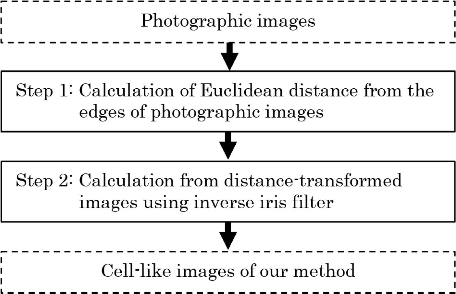
Flow chart of our method.
Step 0: Let input pixel values of RGB on coordinates (i,j) in a color photographic image be fR,i,j, fG,i,j and fB,i,j (i = 1, 2, 3, …, I; j = 1, 2, 3, …, J). The pixel values fR,i,j, fG,i,j and fB,i,j have value of U gradation from 0 to U − 1.
Step 1: Gray-scale pixel values fi,j are calculated as follows.
Edges are extracted from the gray-scale image using EDISON [12] that is a feature extraction tool that integrates edge detection and image segmentation. Shortest Euclidean distances d1,i,j from the edge pixels are calculated at each pixel.
If the Euclidean distances d1,i,j are within mD + D/2 ± 0.5(m = 0, 1, 2, …), the Euclidean distances d2,i,j are set to 0, where D is a positive constant. Otherwise, the Euclidean distances d2,i,j are set to ∞. When the positions where the Euclidean distances d2,i,j are 0 are expressed on the image, it becomes lines of the interval D along the edges.
Scan from the upper left to the lower right of the image, and in the case that the Euclidean distance d2,i,j are 0 at the target pixel (i,j), the Euclidean distances d2,k,l in the range where the Euclidean distance from the target pixel (i,j) is smaller than D are updated to ∞. Where the pixels (k,l) have the Euclidean distances from the target pixel (i,j) smaller than D, and the Euclidean distance d2,i,j of the target pixel (i,j) is not updated. When the positions where the Euclidean distances d2,i,j are 0 are expressed on the image, it becomes dotted lines with the spacing D.
Scan from the upper left to the lower right of the image, and in the case that the Euclidean distance d2,i,j are ∞ at the target pixel (i,j), the Euclidean distance d2,i,j of the target pixel (i,j) is updated to 0 if there is no pixel where the Euclidean distances d2,k,l are 0 in the range where the Euclidean distance from the target pixel (i,j) is smaller than D. In all pixels (i,j), there are pixels that the Euclidean distances d2,k,l are 0 within the radius D. Shortest Euclidean distances di,j from the pixels that the Euclidean distances d2,k,l are 0 are calculated at each pixel. An image composed of the shortest Euclidean distances di,j is called a distance-transformed image.
Step 2: Let output pixel values after processing with iris filter on di,j be IF(di,j). Iris filter is executed with the 2r + 1 peripheral pixels (k,l) in the window of size r. Angles θi,j,k,l between a vector (i − k, j − l) from the peripheral pixels (k,l) to the target pixel (i,j) and a vector ((dk+2,l+2 + dk+2,l+1 + dk+2,l + dk+2,l−1 + dk+2,l-2) − (dk−2,l+2 + dk−2,l+1 + dk−2,l + dk−2,l–1 + dk−2,l-2), (dk+2,l+2 + dk+1,l+2 + dk,l+2 + dk−1,l+2 + dk-2,l+2) − (dk+2,l−2 + dk+1,l−2 + dk,l−2 + dk−1,l−2 + dk−2,l-2)) are computed. Let convergence indices of the target pixel (i,j) be ci,j. The convergence indices ci,j are calculated as follows.
Let minimum and maximum values of ci,j in all pixels be cmin and cmax, respectively. The convergence indices ci,j are converted to Ci,j as follows.
The values IF(di,j) and Ci,j are the same.
Pixel values gR,i,j, gG,i,j and gB,i,j are computed by using inverse iris filter as follows.
3. EXPERIMENTS
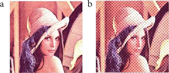
We conducted three experiments. In the first experiment, we visually confirmed the appearance of cell-like images generated from Lenna image shown in Figure 2 by changing the values of the parameters. In the second experiment, we applied our method to six photographic images in (Figure 3). All photographic images used in the experiments comprised 512 * 512 pixels and 256 gradations. In the third experiment, we visually compared cell-like patterns generated by our method and the conventional methods [8,9]. For reference, the edge extracted image and the distance-transformed image (D = 15) of Lenna image are shown in Figure 4a and 4b, respectively.
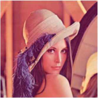
Lenna image.
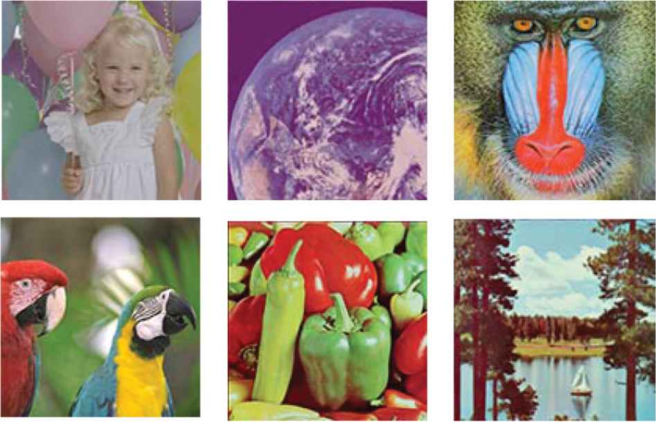
Various photographic images.
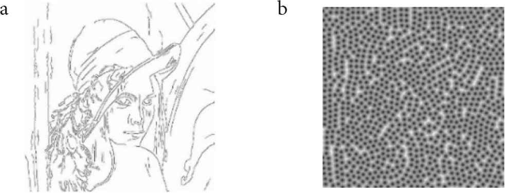
Edge-extracted image and distance-transformed image. (a) Edge-extracted image. (b) Distance-transformed image.
3.1. Experiments with Different Parameter Values
We visually assessed the change in appearance of cell-like images as the value of the parameter D was changed using Lenna image. The value of the parameter D was set to 10, 15 and 20, and the value of the parameters r and a were set to 3 and 0.4, respectively. Cell-like images in the case are shown in Figure 5. The larger the value of the parameter D, the larger cell-like patterns were expressed.
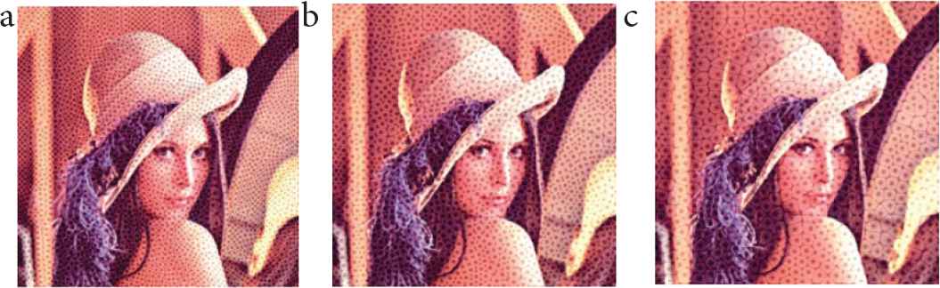
Cell-like images for D = 10, 15 and 20.
We visually assessed the change in appearance of cell-like images as the value of the parameter r was changed using Lenna image. The value of the parameter r was set to 2, 3 and 4, and the value of the parameters D and a were set to 15 and 0.4, respectively. Cell-like images in the case are shown in Figure 6. The larger the value of the parameter r, the larger the cell nuclei of cell-like patterns were expressed.
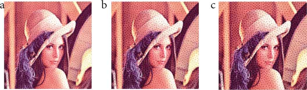
Cell-like images for r = 2, 3 and 4.
We visually assessed the change in appearance of cell-like images as the value of the parameter a was changed using Lenna image. The value of the parameter a was set to 0.2, 0.4 and 0.6, and the value of the parameters D and r were set to 15 and 3, respectively. Cell-like images in the case are shown in Figure 7. The larger the value of the parameter a, the more clearly cell-like patterns were emphasized.
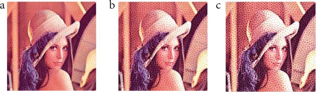
Cell-like images for a = 0.2, 0.4 and 0.6.
3.2. Experiments with Various Photographic Images
We applied our method to six photographic images shown in Figure 3. Referring to the results of the experiments in the previous section, the values of the parameters D, r and a were set to 15, 3 and 0.4, respectively. Cell-like images generated from the six photographic images are shown in Figure 8. In all cell-like images, our method could express cell-like patterns along the edges of photographic images.
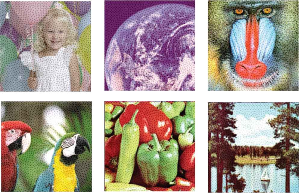
Cell-like images.
3.3. Comparison Experiments with Conventional Methods
We visually compared cell-like patterns generated by the conventional methods [8,9]. Cell-like images generated by the conventional methods [8,9] using Lenna image are shown in Figure 9. Our method could generate cell-like patterns more along the edges than the conventional methods [8,9]. In addition, the cell-like patterns generated by our method were expressed the cell membrane and cell nucleus more clearly than those of the conventional methods [8,9].
4. CONCLUSION
We proposed a method to arrange cell-like patterns along the edges of photographic images. We improved the conventional method [8] by using Euclidean distance from the edges of photographic images. We demonstrated the effectiveness of our method through experiments using various photographic images. The experimental results showed that our method can express cell-like patterns along the edges and can express cell-like patterns with the cell membrane and cell nucleus in cell-like patterns more clearly than the conventional methods [8,9]. In addition, the experimental results showed that the size of cell-like patterns can be changed by changing the values of the parameters in our method.
In future work, we will try to apply our method to videos and three-dimensional data.
CONFLICTS OF INTEREST
The authors declare they have no conflicts of interest.
ACKNOWLEDGMENT
This work was supported by JSPS KAKENHI Grant Number JP19-K12664.
AUTHORS INTRODUCTION
Dr. Toru Hiraoka
 He graduated Doctor course at Design in Kyushu Institute of Design. He is a Professor in the Faculty of Information Systems in University of Nagasaki. His current research interests are non-photorealistic rendering and disaster prevention.
Mr. Kohei Maeda
 He is a student in the Faculty of Information Systems in University of Nagasaki. His current research interests are non-photorealistic rendering and image processing.
REFERENCES
Cite this article
TY  - JOUR
AU  - Toru Hiraoka
AU  - Kohei Maeda
PY  - 2021
DA  - 2021/05/27
TI  - Generation of Cell-Like Images Using Euclidean Distance from Edge
JO  - Journal of Robotics, Networking and Artificial Life
SP  - 14
EP  - 17
VL  - 8
IS  - 1
SN  - 2352-6386
UR  - https://doi.org/10.2991/jrnal.k.210521.004
DO  - 10.2991/jrnal.k.210521.004
ID  - Hiraoka2021
ER  -